


1. Introduction
In many geophysical, astrophysical and engineering problems, fluids are bounded by solid walls and affected by system rotation. Such flows show very complex behaviours especially in turbulent state. Rotating plane Poiseuille flow (RPPF) is one of the canonical models of such flows (Johnston Reference Johnston1998; Jakirlić, Hanjalić & Tropea Reference Jakirlić, Hanjalić and Tropea2002) for its simplicity, and has been studied intensively for decades with experiments and numerical simulations.
Following the analogy between stratified flows in a gravity field and rotating shear flows (Bradshaw Reference Bradshaw1969), the flow near the pressure side of RPPF (with higher pressure caused by the Coriolis force corresponding to the mean streamwise velocity) should be destabilized by rotation, and the flow near the suction side (with lower pressure) should be stabilized. Therefore, the pressure and suction sides are known as the unstable and stable sides, respectively. Turbulent RPPF was first studied by Johnston, Halleent & Lezius (Reference Johnston, Halleent and Lezius1972) and it was found that turbulence is enhanced near the pressure side and suppressed near the suction side, which is in accordance with the thermal analogy (Bradshaw Reference Bradshaw1969). In addition, the local slope of the mean streamwise velocity is found to be approximately twice the spanwise angular velocity  $\varOmega _z^*$, and the Taylor–Görtler vortices (roll cells) are also observed. Other experimental studies include but are not limited to Nakabayashi & Kitoh (Reference Nakabayashi and Kitoh1996, Reference Nakabayashi and Kitoh2005), Maciel et al. (Reference Maciel, Picard, Yan, Gleyzes and Dumas2003) and Visscher et al. (Reference Visscher, Andersson, Barri, Didelle, Viboud, Sous and Sommeria2011).
Nowadays, direct numerical simulation (DNS) is becoming a prevalent tool for studying RPPF. Kristoffersen & Andersson (Reference Kristoffersen and Andersson1993) first performed DNS of turbulent RPPF at small and medium rotation rates, and they also observed the local linear law of mean velocity profiles. With complete data of velocity fields, they extracted secondary flow patterns (Taylor–Görtler vortices) with streamwise average and short time average. Dai, Huang & Xu (Reference Dai, Huang and Xu2016) noticed that the spanwise locations of Taylor–Görtler vortices are continuously changing in a long time period, and introduced the conditional average technique which can better extract the secondary flow structures by eliminating the vortex meandering effect. The results near the pressure side showed that turbulence is relatively stronger in the upwash regions where the wall-normal velocity of secondary flow is pointing away from the pressure side. This is explained by the stretching effect and Coriolis effect on vorticity fluctuation. Our previous works (Zhang et al. Reference Zhang, Xia, Shi and Chen2019; Zhang, Xia & Chen Reference Zhang, Xia and Chen2022) performed DNS on two-dimensional and three-dimensional RPPF and applied the thermal analogy on the analysis of new flow structures and explanation of turbulent statistics. We have proposed a perspective that the basic large-scale flow structures are plume currents fed by small-scale plume-like structures (called as plumes) ejecting from the pressure side, and Taylor–Görtler vortices are driven by those plume currents. Therefore, different from the perspective of Dai et al. (Reference Dai, Huang and Xu2016), our perspective suggests that the relatively strong turbulence in the upwash region near the pressure side is not the consequence but the driving source of the secondary flows. Also, we have noticed that the number of large-scale structures can also change in a long time period, and introduced a clustering algorithm which can extract multiple large-scale patterns in one case. Grundestam, Wallin & Johansson (Reference Grundestam, Wallin and Johansson2008) investigated the cases at medium and high rotation rates and found an extreme laminarization effect by the Coriolis force at high rotation rates, with significant enhancement of mean velocity flux by approximately three times that in the non-rotating case. Wallin, Grundestam & Johansson (Reference Wallin, Grundestam and Johansson2013), Brethouwer et al. (Reference Brethouwer, Schlatter, Duguet, Henningson and Johansson2014) and Brethouwer (Reference Brethouwer2016) focused on the abnormal bursts in systems at high Reynolds numbers and high rotation rates that are expected to be strongly stabilized. The recurrent bursts are explained with the growth and breakup of Tollmien–Schlichting waves near the suction side. Other studies based on DNS can be found in Nagano & Hattori (Reference Nagano and Hattori2003), Yang & Wu (Reference Yang and Wu2012), Hsieh & Biringen (Reference Hsieh and Biringen2016), Brethouwer (Reference Brethouwer2017), Xia, Shi & Chen (Reference Xia, Shi and Chen2016) and Xia, Brethouwer & Chen (Reference Xia, Brethouwer and Chen2018a).
Heat and mass transfer in rotating turbulent systems are closely relevant to many flow machineries, and should also be investigated. Matsubara & Alfredsson (Reference Matsubara and Alfredsson1996) measured the heat and momentum transfer in RPPF, finding that the classical Reynolds analogy is broken by system rotation, and that the heat transfer in RPPF can be almost twice that in the corresponding non-rotating case. Wu & Kasagi (Reference Wu and Kasagi2004) used DNS to study turbulent channel flows with heat transfer under the influence of the combination of any two components of the system angular velocity. They found that spanwise rotation is dominating the variation of heat transfer. Liu & Lu (Reference Liu and Lu2007) used DNS to study scalar transport in RPPF at low and medium rotation numbers, and found that the non-dimensionalized scalar flux decreases with rotation number, which has the opposite trend to the mass flux. They also investigated the terms in the balance equation of convective scalar flux. Brethouwer (Reference Brethouwer2018) investigated the scalar transport in high-Reynolds-number cases with DNS and found that the classical Reynolds analogy does not hold in turbulent RPPF. The distribution of the terms in the balance equations of the variance and convective flux of the scalar are also analysed. Brethouwer (Reference Brethouwer2019) also investigated the influence of scalar boundary conditions, by considering a new case that the scalar varies linearly along the streamwise direction. It was found that the invalidity of the classical Reynolds analogy still holds regardless of the scalar boundary conditions.
As pointed out by one of the anonymous referees, there is another canonical model of rotating wall-bounded turbulence, which is referred to as the spanwise rotating plane Couette flow (RPCF). This flow has also been investigated with several systematic experimental studies (Tillmark & Alfredsson Reference Tillmark and Alfredsson1996; Alfredsson & Tillmark Reference Alfredsson and Tillmark2005; Tsukahara, Tillmark & Alfredsson Reference Tsukahara, Tillmark and Alfredsson2010; Kawata & Alfredsson Reference Kawata and Alfredsson2019) as well as numerical simulations (Bech & Andersson Reference Bech and Andersson1996, Reference Bech and Andersson1997; Gai et al. Reference Gai, Xia, Cai and Chen2016; Xia et al. Reference Xia, Shi, Cai, Wan and Chen2018b; Huang et al. Reference Huang, Xia, Wan, Shi and Chen2019; Xia et al. Reference Xia, Shi, Wan, Sun, Cai and Chen2019). In RPCF, turbulence is enhanced/suppressed when the system angular velocity is antiparallel/parallel to the average vorticity, which is also consistent with the thermal analogy. Furthermore, there are large-scale streamwise vortices, called as Taylor vortices, in RPCF. Therefore, RPCF and RPPF are of high similarity. Nevertheless, two main differences exist between RPPF and RPCF. In RPPF, the two walls are fixed and flow is driven by a streamwise body force (or mean streamwise pressure gradient), whereas in RPCF, the mean streamwise pressure gradient is zero and the flow is driven through the relative motion between two walls. The RPPF usually has stabilized and destabilized regions at the same time, while RPCF is globally stabilized or globally destabilized by rotation. This can be attributed to the different monotonicity in their mean velocity profiles. Furthermore, heat transfer in RPCF was also studied through DNS by Brethouwer (Reference Brethouwer2021, Reference Brethouwer2023), and they reported that the classical Reynolds analogy is invalid in RPCF with heat transfer, which can be successfully explained with the thermal analogy.
To enhance the performance of industrial apparatus with rotating shear flows, it is imperative to consider flow control techniques. In their study, Sumitani & Kasagi (Reference Sumitani and Kasagi1995) investigated the influence of homogeneous injection/suction on turbulent friction and heat transport in non-rotating channel flows. They discovered that injection could increase both the friction coefficient and heat transport, whereas suction had the opposite effect. Furthermore, Choi, Moin & Kim (Reference Choi, Moin and Kim1994) introduced active control in channel flows, applying injection/suction with the opposite wall-normal velocity measured at a specific distance from the wall, which resulted in a reduction of skin friction up to  $25\,\%$ in DNS. By controlling streamwise vortices in a turbulent channel flow with vortex generator jets, Iuso et al. (Reference Iuso, Onorato, Spazzini and di Cicca2002) attained a reduction of local and global skin friction up to $30\,\%$ and $15\,\%$, respectively. In a study on Taylor–Couette flow (TCF), Bakhuis et al. (Reference Bakhuis, Ezeta, Berghout, Bullee, Tai, Chung, Verzicco, Lohse, Huisman and Sun2020) investigated the influence of spanwise-varying wall roughness on large-scale structures and total drag, finding that proper distribution of roughness could rearrange large-scale vortices. Additionally, Zhang et al. (Reference Zhang, Xia, Zhou and Chen2020, Reference Zhang, Chen, Xia, Xi, Zhou and Chen2021) introduced sidewall temperature control in Rayleigh–Bénard convection to fix the separation points of plumes on sidewalls, which led to enhanced large-scale circulation and heat transport.
Although numerous flow control studies have been carried out in non-rotating plane Poiseuille flows, flow control for RPPF, which is a more challenging scenario, has only been investigated in rudimentary studies. Wu, Piomelli & Yuan (Reference Wu, Piomelli and Yuan2019) explored the influence of homogeneous wall roughness on RPPF and discovered that roughness on the stable side can destabilize the flow and counteract the stabilizing effect of rotation. Our previous work (Zhang et al. Reference Zhang, Xia, Shi and Chen2019, Reference Zhang, Xia and Chen2022) has demonstrated that RPPF generates plumes that form large-scale currents similar to those in turbulent TCF. Unlike classical TCF, where plumes emit from both inner and outer walls, plumes can only emit from the unstable side in RPPF. This implies that control on the unstable side and the stable side must have distinct effects. Thus, it is imperative to investigate the performance of flow control on each side of RPPF.
In this paper, we present an injection/suction control strategy on one side of RPPF, which is uniform in the streamwise direction but varies in the spanwise direction, and evaluate its performance on the enhancement of large-scale motions and turbulent transport through DNS. The remainder of the paper is organized as follows. In § 2, we describe the numerical set-up of RPPF with injection/suction control. In § 3, we present and discuss the simulation results of large-scale plume currents and turbulent scalar transport. Finally, in § 4, we summarize our work and provide concluding remarks.
2. Governing equations and numerical description
2.1. Governing equations and boundary conditions
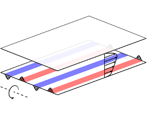
As sketched in figure 1, the incompressible fluid is confined between two infinite parallel plates located at  $y^*=\pm h^*$, where $h^*$ denotes the channel half-width. The entire system rotates along the spanwise ( $z$) direction with a constant angular velocity $\varOmega _z^*$, and the fluid is driven by a constant body force ${\rm d}P^*/{{\rm d}\kern0.7pt x}^*$ in the streamwise ( $x$) direction. According to convention, the lower and upper walls are referred to as the pressure (unstable) and suction (stable) side, respectively, when $\varOmega _z^*>0$. A passive scalar $\phi ^*$ has constant values $\phi _B^*$ and $\phi _T^*$ at the lower and upper walls, respectively. The reference density is denoted as $\rho ^*$, the kinematic viscosity as $\nu ^*$ and the diffusivity of $\phi ^*$ as $\kappa ^*$. In order to use a non-dimensionalization scheme that does not require continual adjustment of the driving force, the reference velocity is chosen as the global friction velocity $u_\tau ^*=\sqrt {-{\rm d}P^*/{{\rm d}\kern0.7pt x}^*(h^*/\rho ^*)}$. By selecting a reference length $h^*$ and a reference passive scalar $\phi _B^*-\phi _T^*$, the governing equations and boundary conditions can be expressed in a non-dimensional form,
 $$\begin{gather} \boldsymbol{\nabla}\boldsymbol{\cdot}\boldsymbol{u}=0, \end{gather}$$
 $$\begin{gather}\frac{\partial\boldsymbol{u}}{\partial t}+\boldsymbol{u}\boldsymbol{\cdot}\boldsymbol{\nabla}\boldsymbol{u} ={-}\boldsymbol{\nabla} p+Re_\tau^{{-}1}\nabla^2\boldsymbol{u}-Ro_\tau\boldsymbol{e}_z\times\boldsymbol{u}, \end{gather}$$
 $$\begin{gather}\frac{\partial\phi}{\partial t}+\boldsymbol{u}\boldsymbol{\cdot}\boldsymbol{\nabla}\phi=Pr^{{-}1}Re_\tau^{{-}1}\nabla^2\phi, \end{gather}$$
 $$\begin{gather}y={-}1:\ \phi=1, \boldsymbol{u}={-}V_B\boldsymbol{e}_y\sum_{k={-}\infty}^{\infty}({-}1)^k\eta\left(\frac{z-kD_J}{d_J}\right)\!, \end{gather}$$
 $$\begin{gather}y={+}1:\ \phi=0, \boldsymbol{u}={+}V_T\boldsymbol{e}_y\sum_{k={-}\infty}^{\infty}({-}1)^k\eta\left(\frac{z-kD_J}{d_J}\right)\!, \end{gather}$$
with global friction Reynolds number  $Re_\tau =u_\tau ^*h^*/\nu ^*$, global friction rotation number $Ro_\tau =2\varOmega _z^*h^*/u_\tau ^*$ and Prandtl number $Pr=\nu ^*/\kappa ^*$. In the velocity boundary condition, $V_B$ and $V_T$ are maximum wall-normal velocity at the lower and upper walls, respectively, $D_J$ is the spanwise distance between the centrelines of two neighbouring slots, $d_J$ is the slot width and
 \begin{equation} \eta(\xi)=\left\{\begin{array}{ll} \cos^2({\rm \pi}\xi), & |\xi|\leq\dfrac{1}{2}\\ 0, & |\xi|>\dfrac{1}{2} \end{array}\right. \end{equation}
is the basic distribution function of wall-normal velocity of each slot.

Figure 1. Sketch of the three-dimensional spanwise RPPF.
2.2. Numerical set-up
In this study, the system is numerically simulated using the AFiD code (van der Poel et al. Reference van der Poel, Ostilla-Mónico, Donners and Verzicco2015), a widely used second-order central-difference method. The flow variables are defined in a rectangular domain that is periodic in the horizontal directions and discretized on a staggered grid. The pressure Poisson equation is solved using a discrete Fourier transform in the horizontal directions and a tridiagonal solver. For time marching, we use the explicit second-order Adams–Bashforth scheme. Since AFiD is designed for simulating Rayleigh–Bénard convection, the  $\phi$ equation could be solved well. To validate the code, we simulate a case without rotation with the following parameters and boundary conditions:
 \begin{align} Re_b&=1333.3,\quad v(x,\pm1,z)={\pm} a\cos(\alpha(x-ct)),\nonumber\\ &\quad a=0.15U_b,\ \alpha=0.5,\ c={-}3U_b. \end{align}
Here,  $U_b$ is the bulk mean velocity and $Re_b=Re_\tau U_b$. As shown in figure 2, the viscous and Reynolds shear stresses computed by the present code match well with the results of Min et al. (Reference Min, Kang, Speyer and Kim2006), illustrating the reliability of the present code. Here, $\langle \varphi \rangle$ denotes the average of an instantaneous field $\varphi$ in the $x$,
$x$,  $z$ and $t$ directions, and $\varphi '=\varphi -\langle \varphi \rangle$ denotes the corresponding fluctuations. At the same time, we use $\langle \varphi \rangle _s$ with $s=y$ or $\{y,z\}$ to denote the averaging in the corresponding direction $s$.
$s$.

Figure 2. Viscous and Reynolds shear stresses of the present validation case and those in Min et al. (Reference Min, Kang, Speyer and Kim2006).
In order to investigate the influence of the present control strategy (figure 1), DNSs are performed at  $Re_\tau =180$ and $300$. The Prandtl number $Pr$ is fixed at $1$, the injection/suction slot width $d_j$ is fixed at ${\rm \pi} /8$, the streamwise period $L_x$ is fixed at $4{\rm \pi}$ and other relevant parameters are listed in table 1. With the chosen meshes, streamwise and spanwise grid spacings are equal to or less than $8.84$ and $4.42$ wall units, respectively. For all cases, wall-normal grid spacing is $0.52$ wall units at the walls and no larger than $2.46$ wall units throughout the whole channel. Such grid spacings are validated by our previous work (Zhang et al. Reference Zhang, Xia and Chen2022). Here, $N_J$ denotes the number of injection slots within every spanwise interval of $2{\rm \pi}$, and thus $D_J=2{\rm \pi} /N_J$ corresponds to a spanwise wavenumber $k_z=N_J$. We choose $V_B$ or $V_T$ being $0.462 N_J^{-1/2} u_\tau$ to fix the root-mean-square (r.m.s.) of $v$ at the injection/suction wall at $0.1u_\tau$, which is below $1\,\%$ of the bulk mean velocity $U_b$. Figure 3 displays the spanwise distributions of wall-normal velocity in the injection/suction control at the bottom plate with $N_J=2$, 3 and 4. It is evident that the peak values of the injection velocity and the distances between the adjacent slots decrease with increasing $N_J$. In the names of the cases listed in table 1, the numbers following ‘R’ denote the rotation number $Ro_\tau$, the numbers following ‘J’ denotes $N_J$ and the letters following $N_J$ denote the bottom plate (B) or top plate (T) injection/suction. Here $Nu$ is the Nusselt number, which characterizes the efficiency of scalar transport, and it is defined in § 3.2. When $Ro_\tau >0$, injections and suctions are applied on either the pressure side or the suction side, while for $Ro_\tau =0$, the control is applied only on the lower wall due to symmetry considerations.
Table 1. Basic physical and computational parameters. Here  $u_{\tau p}$ and $u_{\tau s}$ are the friction velocity at the pressure and suction side, respectively.


Figure 3. Spanwise distributions of wall-normal velocity in the injection/suction control at the bottom plate with different  $N_J$.
2.3. Cluster analysis
As stated in our previous work (Zhang et al. Reference Zhang, Xia and Chen2022), the cross-section slices of flow fields at different times in the same case may show different patterns. This means that simple averaging over the time and streamwise coordinate is not sufficient to characterize large-scale flow structures. The momentum and scalar transport capabilities of these flow patterns should be revealed in general with conditional averaging, while various mode decomposition methods such as real/complex/spectral proper orthogonal decomposition and dynamic mode decomposition (Wallace & Dickinson Reference Wallace and Dickinson1972; Berkooz, Holmes & Lumley Reference Berkooz, Holmes and Lumley1993; Schmid Reference Schmid2010; Towne, Schmidt & Colonius Reference Towne, Schmidt and Colonius2018) are not suitable for conditional averaging. In addition, although Fourier spectral analysis can get the contributions of Fourier modes to the Reynolds stress or convective scalar flux, it always uses sinusoidal functions as basis functions for projection. However, as shown in Zhang et al. (Reference Zhang, Xia and Chen2022), large-scale plume currents in RPPF are non-sinusoidal. This means that Fourier spectral analysis usually requires a combination of several Fourier modes to characterize a simple pattern of plume currents, which may bring unnecessary complexity to physical interpretations. For the analysis of the present system, pattern recognition algorithms should be considered as complementary to the Fourier spectral analysis. Here, we adopt the modified K-means clustering algorithm defined in Appendix C of our previous work (Zhang et al. Reference Zhang, Xia and Chen2022), and a brief description of its main procedures is reviewed as follows.
Each two-dimensional slice  $\tilde {\boldsymbol {u}}_{x',t'}(y,z)=\boldsymbol {u}'(x',y,z,t')$ in the $y$–
$y$– $z$ plane at a certain $x'$ and $t'$ is considered as a vector in an infinite-dimensional space. The angle between the two vectors $\tilde {\boldsymbol {u}}_{x_1,t_1}$ and $\tilde {\boldsymbol {u}}_{x_2,t_2}$ in such a space is defined using the $L^2$ norm. The similarity between these two slices is characterized by the smallest angle $\beta (\tilde {\boldsymbol {u}}_{x_1,t_1}, \tilde {\boldsymbol {u}}_{x_2,t_2})$ between the corresponding vectors with arbitrary spanwise shift.
At the beginning, for integers ranging from  $1$ to $M\in \mathbb {Z}$ (here, $M=10$ is used in present study), clusters $C_N$ with cluster centroids $\boldsymbol {\psi }_N(y,z)$ are chosen corresponding to positive integers $N$ that represent different translation symmetries under $z\rightarrow z+L_z/N$. In each iteration, for each slice $\tilde {\boldsymbol {u}}_{x',t'}$, we calculate the similarity between this slice and all cluster centroids, i.e. $\beta (\tilde {\boldsymbol {u}}_{x',t'}, \boldsymbol {\psi }_N)$, and the slice is categorized temporarily into the cluster $C_L$ if $\beta (\tilde {\boldsymbol {u}}_{x',t'}, \boldsymbol {\psi }_L)$ has the smallest value among all $\beta (\tilde {\boldsymbol {u}}_{x',t'}, \boldsymbol {\psi }_N)$, i.e. the centroid $\boldsymbol {\psi }_L$ is the most similar to this slice. After categorizing all slices, each cluster centroid $\boldsymbol {\psi }_N$ is updated by averaging all slices in its cluster, where before averaging each slice $\tilde {\boldsymbol {u}}_{x',t'}$ is shifted in the spanwise direction with an appropriate displacement that corresponds to $\beta (\tilde {\boldsymbol {u}}_{x',t'}, \boldsymbol {\psi }_N)$. In addition, all cluster centroids $\boldsymbol {\psi }_N$ should be symmetrized following the translation symmetry under $z\rightarrow z+L_z/N$ and reflection symmetry under $z\rightarrow -z$.
After enough iterations, the cluster centroids will converge. However, there will probably be some clusters that include less than  $2\,\%$ of the slices. In such case, these clusters should be deleted, and the iterations should be restarted. Finally, we will get clusters $C_N^{{\dagger}}$ corresponding to converged cluster centroids $\boldsymbol {\psi }_N^{{\dagger}}$, and each containing a proportion $P_N^{{\dagger}} \geq 2\,\%$ of available flow field slices. Therefore, each cluster centroid $\boldsymbol {\psi }_N^{{\dagger}}$ can characterize a pattern that has $N$ large-scale flow structures with almost homogeneous distribution. In the cluster analysis, we use $\langle \varphi \rangle _N$ to denote the conditional average of $\varphi$ in the clusters $C_N^{{\dagger}}$. Please refer to Zhang et al. (Reference Zhang, Xia and Chen2022) for more detailed definitions and procedures.
2.4. Interscale transport equation of turbulent kinetic energy
With respect to a spanwise wavenumber threshold  $k_z^{{\dagger}} \geq 0$, instantaneous velocity fluctuations $\boldsymbol {u}'$ can be decomposed into a large-scale part $\boldsymbol {u}^+(\boldsymbol {x},t;k_z^{{\dagger}} )$ consisting of all spanwise modes with $|k_z|\leq k_z^{{\dagger}}$ and a residual small-scale part $\boldsymbol {u}^-(\boldsymbol {x},t;k_z^{{\dagger}} )$. Similarly, the turbulent kinetic energy $\langle u'_i u'_i\rangle /2$ can be decomposed into $E^+=\langle u_i^+ u_i^+\rangle /2$ and $E^-=\langle u_i^- u_i^-\rangle /2$. By taking the traces of the transport equations of large-scale and small-scale Reynolds stresses (Kawata & Alfredsson Reference Kawata and Alfredsson2018), it is straightforward to derive the interscale transport equations of $E^+$ and $E^-$:
 \begin{equation} \frac{\partial E^\zeta}{\partial t}+\langle\boldsymbol{u}\rangle\boldsymbol{\cdot}\boldsymbol{\nabla} E^\zeta =P^\zeta+T^\zeta-\varepsilon^\zeta+\varPhi^\zeta+D^{\nu,\zeta}+D^{t,\zeta}, \end{equation}
where
 \begin{equation} \left.\begin{array}{c}
\displaystyle P^\zeta={-}\langle u_i^\zeta
u_k^\zeta\rangle\dfrac{\partial\langle u_i\rangle}{\partial
x_k},\quad T^\zeta={-}\left\langle u_i^\zeta
u_k^\zeta\dfrac{\partial u_i^{-\zeta}}{\partial
x_k}\right\rangle +\left\langle u_i^{-\zeta}
u_k^{-\zeta}\dfrac{\partial u_i^\zeta}{\partial
x_k}\right\rangle\!,\\ \displaystyle
\varepsilon^\zeta=\dfrac{1}{Re_\tau}
\left\langle\dfrac{\partial u_i^\zeta}{\partial
x_k}\dfrac{\partial u_i^\zeta}{\partial
x_k}\right\rangle,\quad \varPhi^\zeta={-}\left\langle
u_i^\zeta\dfrac{\partial p^\zeta}{\partial
x_i}\right\rangle\!,\\ \displaystyle
D^{\nu,\zeta}=\dfrac{1}{Re_\tau}\dfrac{\partial^2
E^\zeta}{\partial x_k \partial x_k},\quad
D^{t,\zeta}={-}\dfrac{1}{2}\dfrac{\partial}{\partial x_k}
(\langle u_i^\zeta u_i^\zeta u'_k\rangle +2\langle
u_i^\zeta u_i^{-\zeta} u_k^{-\zeta}\rangle).
\end{array}\right\} \end{equation}
\begin{equation} \left.\begin{array}{c}
\displaystyle P^\zeta={-}\langle u_i^\zeta
u_k^\zeta\rangle\dfrac{\partial\langle u_i\rangle}{\partial
x_k},\quad T^\zeta={-}\left\langle u_i^\zeta
u_k^\zeta\dfrac{\partial u_i^{-\zeta}}{\partial
x_k}\right\rangle +\left\langle u_i^{-\zeta}
u_k^{-\zeta}\dfrac{\partial u_i^\zeta}{\partial
x_k}\right\rangle\!,\\ \displaystyle
\varepsilon^\zeta=\dfrac{1}{Re_\tau}
\left\langle\dfrac{\partial u_i^\zeta}{\partial
x_k}\dfrac{\partial u_i^\zeta}{\partial
x_k}\right\rangle,\quad \varPhi^\zeta={-}\left\langle
u_i^\zeta\dfrac{\partial p^\zeta}{\partial
x_i}\right\rangle\!,\\ \displaystyle
D^{\nu,\zeta}=\dfrac{1}{Re_\tau}\dfrac{\partial^2
E^\zeta}{\partial x_k \partial x_k},\quad
D^{t,\zeta}={-}\dfrac{1}{2}\dfrac{\partial}{\partial x_k}
(\langle u_i^\zeta u_i^\zeta u'_k\rangle +2\langle
u_i^\zeta u_i^{-\zeta} u_k^{-\zeta}\rangle).
\end{array}\right\} \end{equation}
Here,  $\zeta$ can be ‘ $+$’ or ‘ $-$’, and $-\zeta$ denotes the opposite sign of $\zeta$. In the present scenario, we only take discrete values of $k_z^{{\dagger}} =2{\rm \pi} n/L_z$ with $n\in \mathbb {N}$. It should be noted that $T^+(y;k_z^{{\dagger}} )=-T^-(y;k_z^{{\dagger}} )$ denotes the energy exchange between $E^+$ and $E^-$, and a positive sign means the net energy transfer from $k_z>k_z^{{\dagger}}$ to $k_z\leq k_z^{{\dagger}}$ by triad interaction, i.e. ‘inverse’ energy transfer from small-scale to large-scale.
3. Results
3.1. Large-scale motions
In our previous work (Zhang et al. Reference Zhang, Xia and Chen2022), it was demonstrated that plume currents generated by rising plumes from the unstable side are the most significant large-scale structures in RPPF. For a given small or medium  $Ro_\tau$, the number and pattern of plume currents vary continuously with time $t$. To illustrate the patterns and dynamic behaviours of plume currents, figure 4 presents the contours of $v'(t,z)$ in the $t$–
$t$– $z$ plane with $x=y=0$ at $Ro_\tau =5$. From figure 4(a), it can be observed that in the absence of control, two or more plume currents may exist, and they are constantly splitting, merging and oscillating. The supplementary movie 1 available at https://doi.org/10.1017/jfm.2023.1091 displays the instantaneous distributions of the wall-normal velocity in the $y$–
$y$– $z$ plane, demonstrating the chaotic behaviours of plumes and plume currents. With the control of two (R5J2B) and three (R5J3B) injection slots (in a spanwise period) on the unstable side, the number of plume currents (in a spanwise period) is fixed at two and three, respectively, as depicted in figure 4(b,c) and supplementary movie 2. In addition, the plume currents oscillate near the injection slots. It is worth noting that the injection/suction velocity is significantly smaller than the wall-normal velocity in plume currents, since the r.m.s. wall-normal velocity on the unstable side is approximately $0.6\,\%$ of the bulk mean velocity. The relatively weak control exerts a considerable influence by enhancing the self-sustaining process of plume currents (Zhang et al. Reference Zhang, Xia and Chen2022), making the large-scale motions much stronger and more stable. Injection provokes the separation of plumes near the injection slots, and the separated plumes converge into plume currents that induce Taylor–Görtler vortices. These vortices sweep more plumes towards the injection slots. However, with four injection slots (R5J4B), the number of plume currents cannot be fixed and can be two, three or four. The splitting and merging of plume currents is not so frequent as the uncontrolled case, and the spanwise locations of plume currents are often near the injection slots or in the middle of two injection slots. A plume current in the middle of two injection slots is likely to be the result of two neighbouring plume currents that have merged. The relatively smaller influence of four injection slots is probably due to the fact that the intrinsic spanwise distance between plume currents in RPPF at $Re_\tau =180$ and $Ro_\tau =5$ is around ${\rm \pi}$ and $2{\rm \pi} /3$. Therefore, four plume currents (with an average distance of ${\rm \pi} /2$) induced by four injection slots tend to merge. Supplementary movie 3 provides insight into the complex dynamics of plumes and plume currents in R5J4B, which is rather different from that of R5J2B.

Figure 4. Contours of  $v'(0,0,z,t)$ in the $Ro_\tau =5$ cases. The origin of $t$ is chosen within a statistically steady state: (a) R5J0; (b) R5J2B; (c) R5J3B; (d) R5J4B; (e) R5J2T; (f) R5J3T; (g) R5J4T.
Figure 5 shows the contours of  $v'(t,z)$ at $Ro_\tau =10$. The control of two (R10J2B) and three (R10J3B) injection slots on the unstable side have a similar effect on plume currents as those at $Ro_\tau =5$, as depicted in figure 5(b,c). Nevertheless, four injection slots applied to the unstable side can induce four relatively stable plume currents in the $Ro_\tau =10$ case, which is not achieved in the $Ro_\tau =5$ case. We attribute this to the difference in the intrinsic pattern of plume currents at two rotation numbers. As displayed in figures 4(a) and 5(a), the distances between plume currents at $Ro_\tau =10$ are generally smaller than those at $Ro_\tau =5$, which is explained in our previous work (Zhang et al. Reference Zhang, Xia and Chen2022).

Figure 5. Contours of  $v'(0,0,z,t)$ in the $Ro_\tau =10$ cases. The origin of $t$ is chosen within a statistically steady state: (a) R10J0; (b) R10J2B; (c) R10J3B; (d) R10J4B; (e) R10J2T; (f) R10J3T; (g) R10J4T.
For comparison, we present the plume current behaviours under injection/suction control on the stable side in figures 4(e–g) and 5(e–g). It can be observed that the large-scale motions including splitting, merging and spanwise oscillation remain active and appear similar to those in the uncontrolled case. This indicates that the injection/suction control has a negligible influence on the large-scale motions. The primary reason for this is that the separation of plumes on the unstable side is not significantly influenced by the stable side, which is a shared property of both RPPF and penetrative convection.
Figure 6 depicts  $\langle \varPhi _{vv}\rangle _y$, which is the spanwise energy spectra $\varPhi _{vv}(k_z;y)$ averaged along the $y$ direction. The large-scale modes (with $k_z\leq 8$) of the uncontrolled $Ro_\tau =0$ case are found to be much weaker than those of the $Ro_\tau =5$, 10, 30 cases. This can be inferred from figure 6, showing that the peak values in the non-rotating case and the rotating cases are around $0.03$ and within $[0.15,0.25]$, respectively. For the controlled cases, the maximum enhancement of the large-scale modes in the $Ro_\tau =0$ case with injection/suction control is small ( $\sim$10 %) compared with that in the $Ro_\tau =5$ and $Ro_\tau =10$ cases ( $\sim$50 %) under injection/suction control on the unstable side. We attribute this observation to the sensitivity of large-scale modes to the injection/suction control in the presence of plumes and plume currents in rotating cases.

Figure 6. Here  $\varPhi _{vv}(k_z;y)$ averaged over $y$: (a) $Ro_\tau =0$; (b) $Ro_\tau =5$; (c) $Ro_\tau =10$; (d) $Ro_\tau =30$.
Supplemental to figures 4(d) and 5(d), 6(b–d) show the selectivity of large-scale modes to the injection/suction control. Figure 6(b) shows that at  $Ro_\tau =5$, the control with four injection slots has greater enhancement to the $k_z=2$ mode instead of the expected $k_z=4$ mode. Such discrepancy between the control configuration and the plume current distribution disappears in the R10J4B case. It is likely that the dominating mode of the uncontrolled case represents the distribution of plume currents that is most efficient in collecting plumes (totally). In other words, the distances between neighbouring plume currents with the dominating patterns in uncontrolled cases tend to be as small as possible (close to the limit of stability), so that each plume is close enough to a plume current and gets pulled towards it. Therefore, a pattern of plume currents (e.g. four plume currents induced by four injection slots at $Ro_\tau =5$) that is significantly more compact than the dominating pattern in the uncontrolled case (e.g. $k_z=3$ mode at $Ro_\tau =5$) is likely to exceed the maximum ratio between height and distance, which will result in the merging of plume currents.
The above results are still valid in other  $Ro_\tau$, $Re_\tau$ and $L_z$, as shown in figure 7, where different numbers of injection/suction slots are applied at the unstable wall. Figure 7(a), showing the results at $Ro_\tau =2$, indicates that the dominating mode is $k_z=2$ in the uncontrolled case, and only $N_J=2$ can achieve significant enhancement at $k_z=N_J$. In comparison, $N_J=3$ and $N_J=4$ mainly enhance the $k_z=2$ and $k_z=1$ modes, respectively, indicating the merging of too compact plume currents. Figure 7(b), showing the results at $Ro_\tau =5$ at a higher $Re_\tau =300$, indicates that the dominating pattern in the uncontrolled case is also $k_z=3$, which is the same as the case at $Re_\tau =180$ (figure 6b). As a result, the wavenumber of the maximally enhanced mode of each $N_J$ is also the same, which can be found by comparing figures 6(b) and 7(b). It is also worth mentioning that, although $v'_{rms}(-1)/U_b$ is smaller at larger $Re_\tau$, the increase of the $k_z=3$ mode by the $N_J=3$ control becomes even more prominent. This indicates that the present control strategy still works under the increase of Reynolds number. Figure 7(c,d) shows the control effect in a larger $L_z=4{\rm \pi}$ at $Re_\tau =180, Ro_\tau =5$, where the dominant distribution of plume currents has $k_z=2.5$. Figure 7(c) shows that doubling the spanwise domain does not significantly change the locations and heights of the peaks in the spectra, if we assign the energy at each non-integer wavenumber to the nearest integer wavenumber smaller than it. This suggests that $L_z=2{\rm \pi}$ is sufficient for capturing energy spectra at $k_z\geq 2$ and that the control with $L_z/D_J\in \mathbb {Z}$ is robust. With $L_z=4{\rm \pi}$, the control set-ups allow $N_J=2.5$ and $N_J=3.5$, which means that there are 5 and 7, respectively, pairs of control slots in the spanwise domain. Figure 7(d) shows that the control with $2 \leq N_J \leq 3.5$ can still fix and enhance the large-scale motions with $k_z=N_J$. However, it should be noted that the enhancement of large-scale motions does not necessarily lead to very strong enhancement of the turbulent transport, which can be seen from the values of $Nu$ listed in table 1.

Figure 7. Here  $\varPhi _{vv}(k_z;y)$ averaged over $y$: (a) $Re_\tau =180$, $Ro_\tau =2$ and $L_z=2{\rm \pi}$; (b) $Re_\tau =300$, $Ro_\tau =5$ and $L_z=2{\rm \pi}$; (c,d) $Re_\tau =180$, $Ro_\tau =5$ and $L_z=4{\rm \pi}$. The results at $Re_\tau =180$, $Ro_\tau =5$ and $L_z=2{\rm \pi}$ are also shown in (c) for comparison. The results with $L_z=4{\rm \pi}$ in (c) are derived by assigning the value at each non-integer wavenumber to the nearest integer wavenumber smaller than it.
Another interesting phenomenon can be inferred from figure 6(c) corresponding to  $Ro_\tau =10$. It shows that the control with three and four injection slots on the unstable side can induce a large increase in the energy of $k_z=3$ and $k_z=4$ modes, respectively, while the increase of the $k_z=2$ mode caused by two injection slots is relatively small. This indicates that a control pattern which is too sparse compared with the dominating pattern in the uncontrolled case would be less capable of enhancing large-scale motions. The underlying mechanism should be that a sparse pattern of plume currents may fail to collect some near-wall plumes. Those plumes will be dissipated by viscosity rapidly or form new plume currents. Such a mechanism is further supported by figure 6(d), corresponding to $Ro_\tau =30$ at which the $k_z=7$ mode is dominating in the uncontrolled case. It can be seen that three injection slots on the unstable side are less effective than four injection slots. Moreover, two injection slots on the unstable side mainly promote the $k_z=6$ mode, indicating that there are more plume currents between injection slots.
The above discussion can be distilled into a straightforward guideline for the current injection/suction control strategy aimed at enhancing large-scale motions in RPPF. For a fixed  $Re_\tau$ and $Ro_\tau$, utilizing $N_J L_z/2{\rm \pi}$ injection slots on the unstable side with $N_J$ neither significantly smaller nor much larger than the $k_z$ value of the dominant large-scale pattern in the uncontrolled case can substantially amplify plume currents with the corresponding pattern. Injection slots that are too closely spaced will cause plume currents to merge, while excessively sparse injection slots will result in the loss of energy from some plumes or the generation of new plume currents. Consequently, injection/suction control patterns that are either too compact or too sparse, with $N_J L_z/2{\rm \pi}$ injection slots on the unstable side, will not effectively amplify the $k_z=N_J$ mode. Injection/suction control on the stable side has a limited impact on enhancing large-scale motions, as plumes do not originate or detach from this region.
Although spectral analysis is simple to perform, we should notice from figures 4 and 5 that the large-scale plume currents are non-sinusoidal in the spanwise direction, which means that Fourier spectra do not fully characterize the properties and contributions of different plume current patterns. A complementary analysis method should be introduced to specify how frequently each plume current pattern occurs and how much it contributes to turbulent kinetic energy and scalar transport. Also, as observed from figures 4 and 5, the plume currents in uncontrolled cases are continually changing in both number and spanwise locations, and even in controlled cases with pressure side injection/suction (R5J3B and R5J4B), they are not always fully fixed. Consequently, the commonly employed velocity decomposition method by Bech & Andersson (Reference Bech and Andersson1996), which relies on streamwise and time averaging, is unsuitable for RPPF. This is because the secondary field will depend on the start time of averaging if the time interval for averaging is not large enough, or vanish when it is too large. Furthermore, the conditional averaging technique with spanwise shifting introduced by Dai et al. (Reference Dai, Huang and Xu2016) is also not suitable since it assumes that the number of large-scale structures remains fixed. Instead, using the clustering algorithm introduced in our previous work (Zhang et al. Reference Zhang, Xia and Chen2022) and briefly described in § 2.3, we identified the large-scale patterns in RPPF. Figure 8 displays the cluster centroids of R5J0 and R5J2B, which indicates that these two cases differ in the number and shapes of large-scale patterns. Here R5J0 has five large-scale patterns, whereas R5J2B only has four patterns, with the pattern of five plume currents missing. In the R5J2B  $C_1^{{\dagger}}$ pattern, the plume current in the middle is much stronger than the other two. Figure 9(a) illustrates the occurrence possibilities $P_N^{{\dagger}}$ of cluster $C_N^{{\dagger}}$ in different cases. Here $N$ is the number of spanwise periods of the corresponding cluster, and follows the top-down order in figure 8 as well as the supplementary document. As expected, three and four pressure side injection slots promote the pattern of three and four plume currents, respectively. Moreover, two injection slots on the pressure side significantly increase the occurrence possibilities $P_2^{{\dagger}}$ of the $C^{{\dagger}} _2$ pattern to almost double that in the uncontrolled case. In contrast, injection on the suction side has a weaker influence on the number and occurrence possibilities $P_N^{{\dagger}}$ of patterns, consistent with figures 4 and 6. Figure 9(a) also perfectly demonstrates the necessity of introducing cluster analysis as a complement of Fourier spectral analysis. By comparing figures 6(b) and 9(a), it can be found that the control with $N_J=2$ strongly suppressed the pattern of four plume currents (characterized by $C_4^{{\dagger}}$), which seems contradictory to the increase of the $k_z=4$ mode. This is because such increase is achieved by the enhancement of the $C_2^{{\dagger}}$ pattern which is highly non-sinusoidal and contributes not only to the $k_z=2$ mode but also to the $k_z=4$ mode.

Figure 8. Velocity vectors in the  $y$–
$y$– $z$ plane and contours of the wall-normal component of cluster centroids at $Ro_\tau =5$: (a–e) R5J0, clusters $C_1^{{\dagger}} -C_5^{{\dagger}}$; (f–i) R5J2B, clusters $C_1^{{\dagger}} -C_4^{{\dagger}}$.

Figure 9. (a) Occurrence possibilities  $P_N^{{\dagger}}$ of clusters $C_N^{{\dagger}}$ and (b) the $y$–
$y$– $z$ plane average of the conditional average of $v'v'$ within clusters $C_N^{{\dagger}}$ at $Ro_\tau =5$.
Figure 9(b) presents the  $y$–
$y$– $z$ plane average of the conditional average of $v'v'$ within clusters $C_N^{{\dagger}}$ in $Ro_\tau =5$ cases. The results confirm that the pressure side control, featuring two, three or four injection slots, can significantly enhance the large-scale pattern with $N=N_J$, as anticipated. In contrast, the control on the stable side has a negligible effect on the strength of large-scale motions. Although the pattern corresponding to $C_5^{{\dagger}}$ appears to be enhanced by two injection slots on the stable side, its occurrence probability is too low to significantly influence the overall $\langle v'v'\rangle$.
Despite the non-sinusoidal characteristics of large-scale motions, analysis in the spectral perspective may still facilitate intuitive understanding of the complex dynamics, especially interscale energy transfer (Cho, Hwang & Choi Reference Cho, Hwang and Choi2018; Kawata & Alfredsson Reference Kawata and Alfredsson2018; Lee & Moser Reference Lee and Moser2019; Gatti et al. Reference Gatti, Chiarini, Cimarelli and Quadrio2020). Figure 10 displays contours of spanwise spectral turbulent kinetic energy, the related turbulent production term and the interscale transport term at  $Re_\tau =180$ and $Ro_\tau =5$. Here, $e^+(y;k_z)=E^+(y;k_z)-E^+(y;k_z-2{\rm \pi} /L_z)$ and $p^+(y;k_z)=P^+(y;k_z)-P^+(y;k_z-2{\rm \pi} /L_z)$ are the increments of the corresponding cumulative terms (please note that for the two cases considered in figure 10, $L_z=2{\rm \pi}$). As shown in figure 10(a), large-scale energy mainly concentrates in $2\leq k_z\leq 4$, and the $k_z=4$ mode is relatively closer to the pressure side. Figure 10(c) shows that the kinetic energy production mainly occurs at the scales with $5 \leq k_z\leq 12$ locating at wall distances within $10.9\leq y^+\leq 17.4$. The dominating scales of $p^+$ are inconsistent with the spectral distribution of kinetic energy. Figure 10(e) shows an inverse energy cascade at $k_z<12$ near the pressure side, which is in accordance with the self-sustaining process introduced in our previous work (Zhang et al. Reference Zhang, Xia and Chen2022) and is responsible for the inconsistency of dominating scales between $p^+$ and $e^+$. Therefore, the large-scale turbulent kinetic energy in the uncontrolled case, R5J0, is generated at $5 \leq k_z\leq 12$ in the near-wall region and then transferred to $2\leq k_z\leq 4$ away from the wall through the mechanisms of interscale energy transfer and turbulent spatial transport.

Figure 10. Contours of (a,b) spanwise spectra of turbulent kinetic energy  $e^+$; (c,d) spanwise spectra of production term $p^+$; and (e,f) cumulative spanwise spectra of interscale transport term $T^+$ at $Re_\tau =180$ and $Ro_\tau =5$. (a,c,e) for R5J0 and (b,d,f) for R5J2B.
With two injection slots applied to the pressure side, the  $e^+$ of the $k_z=2$ mode increases significantly as shown in figure 10(b), which is consistent with the results in figures 6(b) and 8(b,g). In addition, the large-scale energy spectra of R5J2B become more concentrated in $k_z=2n$ modes with $n\in \mathbb {Z}$. This can be attributed to the non-sinusoidal property of the pattern of two plume currents. Consistently, as depicted in figure 10(d), the kinetic energy production mainly occurs at the scales with $k_z=2n$ ( $n\in \mathbb {Z}$) near the pressure side. However, figure 10(f) shows that the inverse cascade is weakened in R5J2B, although the $e^+$ of the $k_z=2$ mode is significantly enhanced as shown in figures 10(b) and 6(b). This is not surprising because $T^+$ only represents the net energy transfer. When the large-scale energy increases, the interaction between large-scale modes will be stronger and consequently enhances the forward cascade. This neutralizes part of the inverse cascade and results in the decrease of positive $T^+$. Therefore, the enhancement of the $k_z=2$ mode in R5J2B should be directly attributed to the increase of the production term, which is due to the implementation of the two injection slots.
3.2. Turbulent statistics
Figure 11 depicts the mean velocity profiles  $\langle u\rangle$ for all cases. It is observed from figure 11(a) that the mean velocity profiles at $Ro_\tau =0$ become asymmetric in controlled cases, while in the uncontrolled case, it remains symmetric. This is because the injection/suction amplifies the near-wall motions and increases the friction. Figure 11(a–c) illustrate that the pressure side injection/suction can decrease the mean flux, and the decrease is insensitive to the distribution of injection/suction slots. The maximum relative decrease of $U_b$ is $5.93\,\%$, achieved in R5J2B, as listed in table 1. In $Ro_\tau =30$ cases, the influence of the present weak injection/suction is indiscernible, where the relative decrease of $U_b$ is less than $1\,\%$, as shown in figure 11(d) and listed in table 1. For $Ro_\tau >0$ cases, the impact of the suction side injection/suction is small. It is also worth noting that the controlled cases maintain the local linear law of mean velocity profiles, whose slope is approximately $Ro_\tau$. Figure 12 displays the Reynolds shear stress $\langle u'v'\rangle$ for all cases. For the non-rotating cases, as displayed in figure 12(a), the $\langle u'v'\rangle$ profiles of the controlled cases with two, three and four injection slots almost coincide with each other, and they differ from that of the uncontrolled case. However, for the rotating cases, although the mean velocity profiles of the uncontrolled cases and the suction-side controlled cases deviate from those of the pressure-side controlled cases at $Ro_\tau =5$ and $10$, the $\langle u'v'\rangle$ profiles do not show obvious deviation, as displayed in figure 12(b–d). From the mean momentum equation (Xia et al. Reference Xia, Shi and Chen2016)
 \begin{equation} \langle u'v'\rangle=y+(1-u_{\tau p}^2)+\frac{1}{Re_\tau}\frac{{\rm d}\langle u\rangle}{{\rm d}\kern0.05em y}, \end{equation}
it can be inferred that  $u_{\tau p}$ varies very slightly in the controlled and uncontrolled cases at the same $Ro_\tau$, as listed in table 1.

Figure 11. Mean velocity profiles  $\langle u\rangle$ in uncontrolled and controlled cases: (a) $Ro_\tau =0$; (b) $Ro_\tau =5$; (c) $Ro_\tau =10$; (d) $Ro_\tau =30$.

Figure 12. Reynolds shear stress  $\langle u'v'\rangle$ in uncontrolled and controlled cases: (a) $Ro_\tau =0$; (b) $Ro_\tau =5$; (c) $Ro_\tau =10$; (d) $Ro_\tau =30$.
According to the definition in Brethouwer (Reference Brethouwer2018) and equation (2.1), the Nusselt number of  $\phi$ can be defined equivalently (assuming an infinite averaging time) as
 \begin{equation} Nu=\left.-2\frac{\partial\langle\phi\rangle}{\partial y}\right|_{y=\pm1} =1+PrRe_\tau\int_{{-}1}^1{\langle v'\phi'\rangle \,{{\rm d}\kern0.05em y}}. \end{equation}
It is evident that to increase scalar transport, one must increase the convective scalar flux  $\langle v'\phi '\rangle$, as the contribution of molecular diffusion remains constant. Therefore, enhancing the strength of wall-normal motions can be a promising approach.
Figure 13 presents the  $\langle v'v'\rangle$ profiles for all cases. From the values of $\langle v'v'\rangle$ at $y=\pm 1$, it is evident that the present injection/suction is too weak to be noticed at the walls. However, it has a significant impact on the $\langle v'v'\rangle$ profiles for $Ro_\tau \leq 10$ cases, especially in the locations and heights of the peaks. Such influences can be attributed to the difference in strength and height of plume current between clusters, and the variance of the clusters’ occurrence possibilities. For example, $\langle v'v'\rangle$ of case R5J2B has a peak closest to the suction side, and it is the largest in the upper-half of the channel except for an extremely small region at the suction side (where $\langle v'v'\rangle =0.01$ for suction side control cases). This is because the $C_2^{{\dagger}}$ pattern of plume currents has the largest averaged strength and height of plume currents as shown in figure 8(a–e), and such a pattern is dominating (figure 9a) and further strengthened (figure 8g) in R5J2B. At $Ro_\tau =30$, the control has minor influence on $\langle v'v'\rangle$ profiles. It is observed that the effect of the control in non-rotating cases is weakly dependent on the slot distributions. In contrast, the effect of the control is strongly dependent on the slot distributions on the pressure side for $Ro_\tau =5$ and $Ro_\tau =10$ cases.

Figure 13. Here  $\langle v'v'\rangle$ in uncontrolled and controlled cases: (a) $Ro_\tau =0$; (b) $Ro_\tau =5$; (c) $Ro_\tau =10$; (d) $Ro_\tau =30$.
The profiles of convective scalar flux denoted by  $\langle v'\phi '\rangle$ are presented in figure 14. Figure 14(a) demonstrates that the increase of $\langle v'\phi '\rangle$ is not strongly dependent on the distribution of injection/suction slots in non-rotating cases. This behaviour is similar to $\langle u\rangle$, $\langle u'v'\rangle$ and $\langle v'v'\rangle$ in non-rotating cases. However, when $Ro_\tau$ is non-zero and not very large, the distribution of injection/suction slots on the unstable side becomes a crucial factor in turbulent scalar transport. Figure 14(b) reveals that the largest relative enhancement of $\langle \langle v'\phi '\rangle \rangle _y$ is $17.2\,\%$ in R5J2B, which is almost three times the relative decrease of $U_b$ in this case. There are two main reasons for this observation. Firstly, case R5J2B exhibits a significant increase of large-scale wall-normal kinetic energy, similar to case R5J3B, as shown in figure 6(b). Secondly, two plume currents have a larger spanwise distance than three plume currents, and a greater distance between plume currents may lead to higher efficiency of scalar transport, as discussed in our previous work (Zhang et al. Reference Zhang, Xia and Chen2022). This is supported by figure 15(a), where the $y$–
$y$– $z$ plane average of the conditional average of $v'\phi '$ within clusters $C_N^{{\dagger}}$ at $Ro_\tau =5$ is shown. This can be used to illustrate the scalar transport capability of different large-scale patterns. Notably, two injection slots on the pressure side can significantly increase the scalar transport capability of the pattern with two plume currents ( $C_2^{{\dagger}}$ shown in figure 8g). Under the control of three injection slots on the pressure side, the pattern with three plumes becomes the most efficient in scalar transport. However, the impact of achieving this pattern through the use of three injection slots on the pressure side is relatively minor, combined with the occurrence possibility $P_3^{{\dagger}}$ of cluster $C_3^{{\dagger}}$ shown in figure 9(a). More quantitatively, figure 15(b) shows the weighted contribution of $\langle v'\phi '\rangle$ from each cluster $C_N^{{\dagger}}$. It shows that the main contribution to $\langle v'\phi '\rangle$ comes from cluster $C_2^{{\dagger}}$ in R5J2B, while it is from clusters $C_1^{{\dagger}}$ for other cases. At $Ro_\tau =10$, three injection slots on the unstable side slightly outperform two injection slots, as shown in figure 14(c). This is because $\langle v'v'\rangle$ in case R10J3B is generally larger than that in case R10J2B, as demonstrated in figure 13(c), and the higher efficiency of two plume currents in scalar transport cannot compensate for their lower strength. When $Ro_\tau =30$, the increase of $\langle v'v'\rangle$ and $\langle v'\phi '\rangle$ induced by injection/suction on the unstable side is relatively small compared with the corresponding cases at $Ro_\tau =5$ or $Ro_\tau =10$, as shown in figure 14(d). This suggests that turbulent kinetic energy and scalar transport are only sensitive to the control when the scale of the control pattern is close to the intrinsic scale of large-scale motions. Similar to $\langle u\rangle$, $\langle u'v'\rangle$ and $\langle v'v'\rangle$, convective scalar transport is weakly influenced by injection/suction on the stable side. This also indicates that the present control strategy increases the scalar transport not simply by blowing $\phi$ at the boundary into the fluid, but by varying the distribution and strength of plume currents.

Figure 14. Convective scalar flux  $\langle v'\phi '\rangle$ in uncontrolled and controlled cases: (a) $Ro_\tau =0$; (b) $Ro_\tau =5$; (c) $Ro_\tau =10$; (d) $Ro_\tau =30$.

Figure 15. (a) The  $y$–
$y$– $z$ plane average of the conditional average of $v'\phi '$ within clusters $C_N^{{\dagger}}$ and (b) the weighted contribution of $\langle v'\phi '\rangle$ from each cluster $C_N^{{\dagger}}$ at $Ro_\tau =5$.
For a better demonstration of the local impact of injection/suction, the relative enhancement of convective scalar flux  $\langle v'\phi '\rangle$ is presented in figure 16. It is evident from figure 16(b–d) that pressure side injection/suction usually induces a significant local enhancement of convective scalar transport. The corresponding peaks locate at approximately $y=0.7$ for $Ro_\tau =5$ and $10$, and at around $y=0.4$ for $Ro_\tau =30$. This is due to the rise in both the mean strength and height of plume currents through effective injections, evident from the comparison between figures 8(b) and 8(g). With stable plume currents, plumes are more likely to penetrate deeper into the stable region near the suction side. Since the mean scalar gradient is relatively large in the stable region due to the weaker convective flux, plumes that approach the suction side will induce significant local enhancement of scalar transport. From another perspective, the uncontrolled cases exhibit a rapid drop in $\langle v'\phi '\rangle$ near the suction side, and the injections can strengthen the plume currents and consequently delay the decline.

Figure 16. Relative deviation of  $\langle v'\phi '\rangle$ from that of the corresponding uncontrolled cases: (a) $Ro_\tau =0$; (b) $Ro_\tau =5$; (c) $Ro_\tau =10$; (d) $Ro_\tau =30$.
Based on the discussions presented above, we can claim that the present injection/suction control on the unstable wall can achieve an  $O(10\,\%)$ enhancement of turbulent scalar transport with control velocity $O(1\,\%) U_b$. When $v'_{rms}(-1)$ is fixed at $0.1u_\tau$, only in rotating cases is scalar transport sensitive to injection/suction velocity distribution. It is recommended that the distance between injection slots be equal to or slightly larger than the dominant spanwise wavelength $\lambda _z=2{\rm \pi} /k_z$ observed in the uncontrolled case, in order to ensure a satisfactory enhancement of plume currents and scalar transport efficiency.
The statement on the injection slot spacing for optimal scalar transport enhancement is still valid at different  $Ro_\tau$, $Re_\tau$ or in a larger spanwise domain. This is demonstrated in figure 17, which exhibits the profiles of the convective scalar flux $\langle v'\phi '\rangle$ at three new sets of parameters. As shown in figure 7, the wavenumbers $k_z$ of the dominating spanwise Fourier modes of the three uncontrolled cases, R2J0, R5J0_Re+ and R5J0_Lz+, are 2, 3 and 2.5, respectively. Correspondingly, at $Re_\tau =180$ and $Ro_\tau =2$, two injection slots achieve maximum scalar transport in a spanwise domain of $L_z=2{\rm \pi}$, as shown in figure 17(a). Likewise, two injection slots in $L_z=2{\rm \pi}$ achieve maximum scalar transport at $Re_\tau =300$ and $Ro_\tau =5$, as shown in figure 17(b). Figure 17(c) demonstrates that the largest enhancement of $\langle v'\phi '\rangle$ and $Nu$ at $Re_\tau =180, Ro_\tau =5$ and $L_z=4{\rm \pi}$ is achieved by using four injection slots ( $N_J=2$). Figure 17(c) demonstrates that four injection slots ( $N_J=2$) provides the largest enhancement of $\langle v'\phi '\rangle$ and $Nu$ at $Re_\tau =180$, $Ro_\tau =5$ and $L_z=4{\rm \pi}$, where the relative increase of turbulent transport is 16.1 %. For the control with five injection slots ( $N_J=2.5$), the enhancement of the turbulent scalar transport is also significant, which is 14.5 %. It is worth noting that, although the controls with $N_J=3$ and 3.5 can greatly amplify the wall-normal kinetic energy at $k_z=3$ and 3.5, respectively, as shown in figure 7(d), they can only enhance the turbulent scalar transport by 5.1 % and 2.7 %. These results not only demonstrate the robustness of the control strategy, but also strongly support our criterion on the optimal choice of injection/suction distribution for scalar transport enhancement, i.e. the distance between injection slots should be equal to or slightly larger than the dominant spanwise wavelength in the uncontrolled case.

Figure 17. Convective scalar flux  $\langle v'\phi '\rangle$ in uncontrolled and controlled cases: (a) $Re_\tau =180$, $Ro_\tau =2$, $L_z=2{\rm \pi}$; (b) $Re_\tau =300$, $Ro_\tau =5$, $L_z=2{\rm \pi}$; (c) $Re_\tau =180$, $Ro_\tau =5$, $L_z=4{\rm \pi}$.
4. Conclusion
This paper presents an injection/suction control approach for RPPF, whose wall-normal velocity at the controlling wall is uniform in the streamwise direction but varies in the spanwise direction, aiming to increase the strength of plume currents and enhance the turbulent scalar transport. A general finding is that system rotation greatly complicates the influence of flow control. Specifically, rotation number and injection/suction distribution are both decisive. Based on the systematic analysis, we have arrived at the following three conclusions. Firstly, the injection/suction control on the suction side wall has a minor effect, and that the control should be implemented at the pressure side. Secondly, the control at the pressure side, with proper control parameters where the distance between injection slots is neither significantly smaller nor much larger than the dominant spanwise wavelength of plume currents in the uncontrolled case, can well fix the large-scale patterns of plume currents, and enhance the scalar transport. Thirdly, the finding regarding the proper control with small injection/suction velocity is valid across different  $Re_\tau$, $Ro_\tau$ and spanwise domain sizes that are considered in the present study.
Supplementary material and movies
Supplementary material and movies are available at https://doi.org/10.1017/jfm.2023.1091.
Funding
This work was supported by the National Natural Science Foundation of China (NSFC grant nos. 92152101, 12302284, 11988102) and the Ningbo Science and Technology Bureau (grant no. 2023Z227). The numerical simulations were finished at National Supercomputer Center in Guangzhou (Tianhe-2A), China.
Declaration of interests
The authors report no conflict of interest.


