


I. INTRODUCTION
Hydrogen production from electrocatalytic splitting of water to minimize global carbon emissions and to maintain sustainability is compelling. Reference Turner1 To achieve this goal, highly active catalysts for the hydrogen evolution reaction (HER) are indispensable. Reference Pu, Liu, Tang, Asiri and Sun2 Noble metals, such as platinum (Pt), have been considered as one of state-of-the-art catalysts for HER in acidic medium because their free energy of hydrogen adsorption is approximately zero. Reference Zou and Zhang3–Reference Norskov and Christensen5 Unfortunately, the high cost and scarcity seriously hinder its widespread application. It is imperative to design efficient kinds of HER catalyst that are made from earth-abundant elements. Indeed, tremendous efforts have been devoted in developing precious metal-free catalysts with high activity for HER over the past years. Reference Tang, Cheng, Pu, Xing and Sun6–Reference Qu, Yang, Chai, Tang, Shao, Kwok, Yang, Wang, Chua, Wang, Lu and Pan15 Among various materials, transition metal dichalcogenides (TMDs) have attracted increasing attention owing to their high catalytic activity. Reference Jaramillo, Jørgensen, Bonde, Nielse and Horch7–Reference Qu, Yang, Chai, Tang, Shao, Kwok, Yang, Wang, Chua, Wang, Lu and Pan15 Experimental and theoretical studies showed that the HER performances of TMDs were directly related to their composition, Reference Jiao, Zheng, Jaroniec and Qiao16–Reference Tsai, Abild-Pedersen and Nørskov20 exposed active edge sites, Reference Yan, Tian, Li, Atkins, Zhao, Murowchick, Liu and Chen4,Reference Jaramillo, Jørgensen, Bonde, Nielse and Horch7,Reference Kong, Wang, Cha, Pasta, Koski, Yao and Cui9,Reference Kibsgaard, Chen, Reinecke and Jaramillo21–Reference Wang, Liu, Zhu, Papakonstantinou, Hu, Liu and Li23 and conductive substrates. Reference Jaramillo, Jørgensen, Bonde, Nielse and Horch7,Reference Hu, Bian, Tai, Zeng, Wang, Huang, Xiong and Zhu24–Reference Tang, Xie, Sun, Asiri and He30 Recently, various nanostructured Ni-based TMDs demonstrated impressive performances in HER. Reference Pu, Liu, Tang, Asiri and Sun2,Reference Jiang, Liu and Sun31,Reference Wu, Li, Liu, Yang, Lian, Asefa and Zou32 Particularly, Ni3S2 nanomaterial has been considered as one of the promising candidates for HER due to its low cost, high abundance, and easy preparation processing. Reference Chen, Ma, Liu, Li, Su, Davey and Qiao33–Reference Tang, Pu, Liu, Asiri, Luo and Sun38 Many studies showed that the electrocatalytic activities of three-dimensional (3D) Ni3S2 supported on Ni foam were higher than those of the molybdenum dichalcogenides in basic media because of their intrinsically high catalytic activity toward HER. Reference Feng, Yu, Wu, Li, Li, Sun, Asefa, Chen and Zou35,Reference Lin, Liu and Dai36,Reference Yan, Tian, He and Chen39 Note that 3D structure can (i) facilitate the diffusion of electrolyte and hydrogen bubbles, (ii) ensure a large surface area associated with the nanostructured active materials along with the absence of binder, accelerating the surface reaction, and (iii) enable the direct contact of the nanostructured active materials to the underneath conductive substrate which ensures a possible high efficiency. Reference Yan, Li, Lyu, Song, He, Niu, Liu, Hu and Chen40,Reference Wu, Ren, Wen, Gao, Zhao, Chen, Zhou, Li and Cheng41 However, to the best of our knowledge, little report has reported on the direct synthesis of 3D Ni3S2/graphene composite nanosheets on nickel foam (NF). Graphene displays extraordinary electronic conductivity, large specific surface area, and good chemical stability. Reference Huang, Zeng, Fan, Liu and Zhang42 The introduction of graphene is expected to improve the conductivity of the composites and facilitate the electron transfer, which is very important for high HER performance. Reference Jaramillo, Jørgensen, Bonde, Nielse and Horch7,Reference Jiang, Bogoev, Popova, Gul, Yano and Sun37,Reference Merki, Fierro, Vrubel and Hu43,Reference Lv, Miura, Yang and Liang44
In this work, we present a facile method to synthesize 3D Ni3S2-rGO (reduced graphene oxide) nanosheets composite on NF. This composite shows outstanding HER catalytic ability. The effect of the rGO on the morphology, electrochemically active surface area (ECSA), and number of active sites of the Ni3S2 nanosheets were proposed. Compared to the Ni3S2@NF, the HER performance of the Ni3S2-rGO@NF composite is greatly improved with a near-zero onset potential.
II. EXPERIMENT SECTION
A. Materials
Natural graphite powder was purchased from Alfa Aesar, Tianjin, China (99.8%). Potassium permanganate (KMnO4, 99%), hydrogen peroxide (H2O2, 30 wt%), concentrated sulfuric acid (H2SO4, 98 wt%), concentrated hydrochloric acid (HCl, 37 wt%), phosphorus pentoxide (P2O5, 98%), potassium persulfate (K2S2O8, 99.5%), potassium hydroxide (KOH, 85%), acetone (CH3COCH3, 99%), and thiourea (NH2CSNH2, 99%) were purchased from Sinopharm Chemical Co., Ltd., Beijing, China. NF (99.95%) was purchased from Shengyuan Co., Ltd., Shanghai, China. The deionized (DI) water was prepared by the Millipore Milli-Q water purification system (18.2 MΩ; Millipore, Molsheim, France). All reagents were used as-received.
1. Synthesis of graphene oxide (GO)
GO was prepared by a modified Hummers method. A typical synthetic procedure can be divided into two steps. The first step is the preoxidation process. Briefly, 2.0 g of graphite was added to a mixture of 30 mL of concentrated H2SO4, 1 g of K2S2O8, and 1 g of P2O5. The mixture was placed in an oil bath and continuously stirred at 80 °C for 6 h. The above mixture was diluted with 500 mL of DI water and then filtered through a 0.2 μm film and washed with DI water repeatedly until the pH is reached ∼7. The filter cake was dried in an oven at 60 °C for 12 h. The second step is the oxidation process. 3 g of KMnO4 was added gradually to 30 mL of concentrated H2SO4 in an ice water bath with stirring. 1 g of the pretreated graphite was added slowly to the mixture. The mixture was stirred at 20 °C for 1 h and then at 35 °C for 8 h before 50 mL of DI water was added to the mixture. After 15 min of stirring, the reaction was terminated by addition of 300 mL of DI water and 5 mL of H2O2 solution (30 wt%), and the mixture became bright yellow. Subsequently, the suspension was filtered, and rinsed with enough aqueous HCl (5 wt%) and then with a large amount of DI water until the pH reached ∼7. Finally, the as-prepared GO hydrogel was dispersed in water under ultrasonic treatment to form a homogeneous GO solution with a concentration of 8.8 mg/mL.
2. Synthesis of Ni3S2-rGO@NF composite
NF was pretreated by acetone, 3 M HCl and DI water, respectively, at room temperature for 10 min under ultrasonication. Typically, 0.8 g of thiourea was dispersed in 70 mL of GO solution (2.14 mg/mL) at room temperature with vigorous stirring for 30 min until a black homogeneous slurry was obtained. The mixture was then added into a Teflon lined stainless steel autoclave (100 mL) with a piece of the pretreated NF (1 × 1 cm). Hydrothermal reaction was carried out at 160 °C for 6 h. When the autoclave was cooled down to room temperature, the product was collected, washed with DI water and ethanol, and dried overnight in a vacuum oven at 60 °C. The resultant product was denoted as Ni3S2-rGO@NF. For comparison, Ni3S2@NF composite was prepared with the same procedures without GO.
B. Physical characterization
X-ray diffraction (XRD) patterns were recorded using a Rigaku smartlab X-ray diffractometer (Rigaku Corp, Tokyo, Japan) with Cu Kα radiation (λ = 0.15406 nm). Morphologies of the samples were characterized using scanning transmission electron microscopy (STEM; Tecnai G2 20 FEI Company, Eindhoven, Holland). The surface chemical composition and the atomic valence states were investigated by using X-ray photoelectron spectroscopy (XPS). XPS was performed under normal mode by using a Thermo Fisher Scientific Theta Probe Angle-resolved XPS system with monochromatic Al Kα X-ray (Thermo Fisher Scientific, Waltham, Massachusetts). The Raman Spectroscopy (Renishaw, London, U.K.) was also carried out with 514.5 nm excitation wave length.
C. Electrochemical characterization
All electrochemical measurements were performed in a three-electrode system at CHI660E electrochemical station (CH Instruments, Inc., Shanghai, China) using a saturated calomel electrode (SCE) and a Pt wire as the reference electrode and the counter electrode. The as-obtained samples were directly used as the working electrode. Electrochemical experiments were performed in 1 M KOH electrolyte. Linear sweep voltammetry (LSV) was conducted at a scan rate of 5 mV/s. Stability was examined by CV measurement for 1000 cycles at a scan rate of 50 mV/s in the potential range from −0.2 to 0.5 V versus SCE. The I–t curve and V–t curve were also recorded with a preset potential (50 mV versus RHE) and current density (15 mA/cm2), respectively. Impedance measurement was carried out in the frequency range from 0.01 Hz to 100 kHz with an amplitude potential of 5 mV. Turnover frequency (TOF) was evaluated by CV tests in the electrolyte of phosphate buffered solution (pH = 7.0) at a scan rate of 50 mV/s in the potential range from −0.6 to 0.6 V versus SCE. The double layer capacitance (C dl) was measured using a simple cyclic voltammetry method. The voltage window of cyclic voltammograms was −0.05 to 0.05 V versus SCE. The scan rates were 20, 40, 60, 80, 100, 120, 140, 160, 180, and 200 mV/s. C dl was estimated by plotting the ∆j = (j a − j c) at 0.0 V versus SCE against the scan rate, where the slope was twice as the C dl.
III. RESULTS AND DISCUSSION
Figure 1 shows the SEM images of the Ni3S2@NF and Ni3S2-rGO@NF. For comparison, bare NF presents a smooth surface as shown in Fig. S1. Figure 1(a) displays the SEM image of the Ni3S2@NF, showing that the NF is uniformly covered with interconnected Ni3S2 nanosheets. Figure 1(b) reveals that the introduction of rGO reduced the size of the Ni3S2 nanosheets. Moreover, the Ni3S2 nanosheets are anchored on rGO surface and interconnected to form the three-dimensional porous architecture. This result indicates that the Ni3S2 nanosheets have successfully fixed on the rGO. Reference Zheng, Xu, Yan, Wang, Wang and Yang29 The microstructure of the Ni3S2-rGO@NF composite was further examined by TEM [Fig. 1(c)]. The TEM image verifies that the ultrathin Ni3S2 nanosheets are homogeneously dispersed on the rGO sheets. HRTEM image shows that the lattice spacing is 0.287 nm [Fig. 1(d)], which corresponds to the (110) plane of the rhombohedral Ni3S2 (JCPDS 44-1418).

FIG. 1. SEM images of (a) Ni3S2@NF and (b) Ni3S2-rGO@NF. TEM (c) and HRTEM (d) images of Ni3S2-rGO@NF.
Fig. 2 depicts the dark field image and energy-disperse spectroscopy (EDS) elemental mapping of Ni3S2-rGO@NF composite, which clearly shows that element Ni, S, and C distribute uniformly in the entire surface of the composite, suggesting the homogeneous growth of Ni3S2 on rGO sheets. The EDS result also indicates the existence of O in Ni3S2-rGO@NF composite, which could be mainly introduced by the rGO. To further acquire the structural information of the samples, XRD measurement was carried out. As shown in Fig. 3(a), the XRD peaks at 2θ = 21.8, 31.1, 37.8, 49.7, and 55.1° are indexed to the (101), (110), (021), (211), and (122) planes of the rhombohedral Ni3S2 (JCPDS 44-1418), respectively. Reference Feng, Yu, Wu, Li, Li, Sun, Asefa, Chen and Zou35,Reference Tang, Pu, Liu, Asiri, Luo and Sun38 The diffraction peaks at 44.5, 51.8, and 76.4° are assigned to the (111), (200), and (220) planes of the cubic nickel (JCPDS 04-0850). Reference Ouyang, Wang, Wang, Zhang, Wu, Ma, Dou and Wang34,Reference Feng, Yu, Wu, Li, Li, Sun, Asefa, Chen and Zou35,Reference Tang, Pu, Liu, Asiri, Luo and Sun38 Owing to the relatively low content of the rGO, only a very weak peak at ∼26° corresponding to the (002) plane of rGO is observed. Raman spectroscopy was carried out to further characterize the as-synthesized Ni3S2/rGO composite. Fig. 3(b) exhibits a series of obvious peaks at 212, 301, and 348 cm−1 which are attributed to the vibration of Ni3S2. Reference Ouyang, Wang, Wang, Zhang, Wu, Ma, Dou and Wang34 The stretching motion of the sp 2 carbon atoms is assigned to the G-band at 1598 cm−1. The D-band located at the 1350 cm−1 is attributed to defects and disorder in the graphene layers. Reference Lv, Miura, Yang and Liang44 All these results illustrate that 3D Ni3S2-rGO@NF was successfully prepared without other impurity.
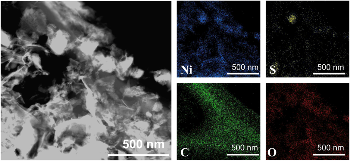
FIG. 2. Dark field image and elemental mapping of Ni3S2-rGO@NF.

FIG. 3. XRD pattern (a) and Raman spectrum (b) of the Ni3S2-rGO@NF.
The atomic valence states of the Ni3S2-rGO@NF composite were further studied by XPS analysis. The XPS survey spectrum [Fig. 4(a)] of the Ni3S2-rGO@NF composite displays an overview of the surface chemical composition, signaling the presence of Ni, S, C, and O. The high-resolution XPS spectrum of the Ni 2p could be fitted into four peaks [Fig. 4(b)]. Two main peaks located at 855.9 and 873.7 eV are attributed to Ni 2p 3/2 and Ni 2p 1/2, respectively. Reference Yan, Tian and Chen45 Figure 4(c) shows the high-resolution S 2p XPS spectrum. The two peaks centered at 163 and 164 eV correspond to the S 2p 3/2 and S 2p 1/2, respectively. Reference Zhang, Liu, Liang, Dong and Feng13,Reference Faber, Dziedzic, Lukowski, Kaiser, Ding and Jin14 The high-resolution spectrum of O 1s can be deconvoluted into three peaks [Fig. 4(f)]: 531.2 eV (C=O), 532 eV (C–O–Ni), and 533.4 eV (C–O). Reference Teng, Zhao, Zhang, Li, Xia, Zhang, Zhao, Du, Du, Lv and Świerczek46,Reference Zhou, Wang, Yin, Li, Li and Cheng47 Noting that the O 1s peak from the C–O–metal bond is located at 530–533 eV. Reference Teng, Zhao, Zhang, Li, Xia, Zhang, Zhao, Du, Du, Lv and Świerczek46 Therefore, the existence of C–O–Ni bond can be confirmed in the Ni3S2-rGO@NF composite. Reference Zhou, Wang, Yin, Li, Li and Cheng47 The enhanced interfacial interaction between the rGO and Ni3S2 through the C–O–Ni bonding is considered beneficial for enhancing the electron transport and structural stability of the Ni3S2/graphene electrode. Reference Zhou, Wang, Yin, Li, Li and Cheng47 Figure 4(e) shows the deconvoluted C 1s XPS spectrum, where four different peaks are corresponding to C=C/C–C (284.8 eV), C–O (285.9 eV), C=O (287.3 eV), and O=C–O (288.8 eV) groups, respectively. Reference Dao, Hoa, Larina, Lee and Choi48 For comparison, Fig. 4(f) shows the fitted C 1s XPS spectrum of pure GO. Obviously, the intensities of the peaks from the C–O and C=O groups decrease dramatically, suggesting that the GO was reduced to form rGO during the hydrothermal treatment. Reference Zheng, Xu, Yan, Wang, Wang and Yang29

FIG. 4. (a) XPS survey spectrum. High-resolution (b) Ni 2p, (c) S 2p, (d) O 1s and (e) C 1s spectra of the Ni3S2-rGO@NF composite. (f) High-resolution C 1s spectrum of pure GO.
The catalytic performance of the Ni3S2-rGO@NF composite was investigated in 1.0 M KOH solution using a standard three-electrode system. For comparison, the commercial Pt/C, Ni3S2@NF composite, and bare Ni foam were also tested under identical conditions. Figure 5(a) shows the polarization curves in the potential window of 0.2 to −0.4 V versus RHE. The Ni3S2-rGO@NF composite shows significantly enhanced HER activity compared with the Ni3S2@NF composite. In sharp contrast, the bare Ni foam exhibits inferior HER activity. The onset potential for the Ni3S2-rGO@NF composite is near 0 V versus RHE, which is comparable to that of the commercial Pt/C catalysts. The onset potentials of the Ni3S2@NF composite and Ni foam are 0.064 and 0.13 V versus RHE, respectively, confirming the superior HER activity of the Ni3S2-rGO@NF composite. Moreover, at a current density of 10 mA/cm2, the overpotentials needed for the Ni3S2@NF composite and bare Ni foam are 161 and 243 mV, respectively. By contrast, the Ni3S2-rGO@NF composite displays only a very low overpotential of ∼44 mV. This is also superior to those of the other reported Ni3S2-based materials (Table I). These results reveal high catalytic activity of the Ni3S2-rGO@NF composite toward HER.
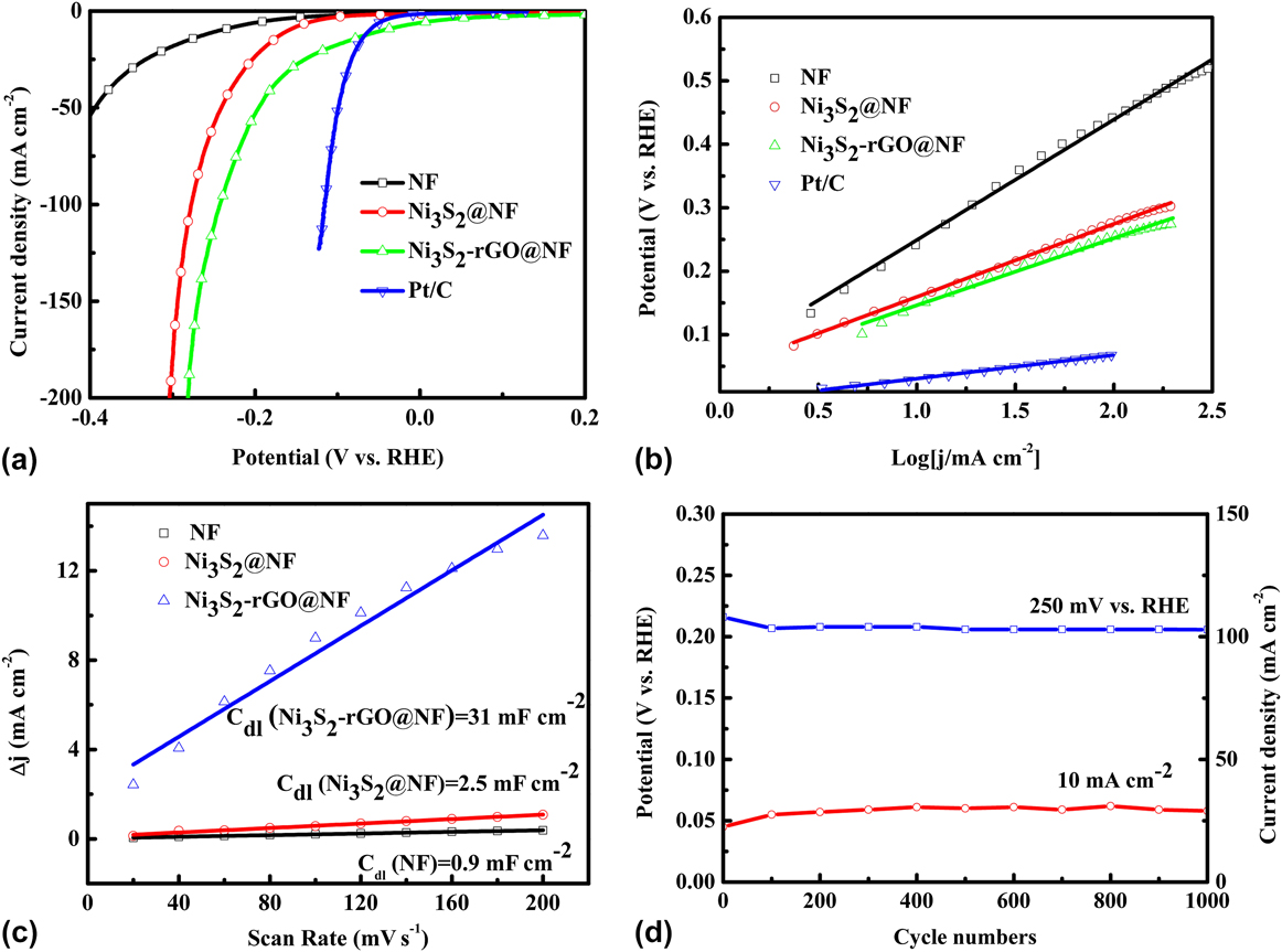
FIG. 5. Electrochemical measurements of various materials in 1 M KOH aqueous solution: (a) polarization curves, (b) Tafel plots (the dashed lines are the linear fitting results of corresponding Tafel curves), (c) charging current density difference (∆j = j a − j c) plotted against scan rate (the solid lines are the fitted results), and (d) stability test.
TABLE I. Comparison of key parameters of 3D Ni3S2-rGO@NF HER electrocatalyst.
The Tafel plots, which are derived from the linear regions of the polarization curves, are shown in Fig. 5(b). The slope values for the bare Ni foam, Ni3S2@NF, Ni3S2-rGO@NF, and commercial Pt/C are 189, 115, 106, and 33 mV/dec, respectively. The Tafel slope of the Ni3S2-rGO@NF electrode is similar to that of the Ni3S2-based electrocatalysts reported in recent years (Table I). The Tafel slope is related to the mechanism of the HER process. In alkaline solutions, Tafel slope of 120, 40, or 30 mV/dec is expected if the Volmer (H2O + e− → Had + OH−), Heyrovsky (H2O + Had + e− → H2 + OH−), or Tafel (Had + Had → H2) step is the rate-determining step, respectively. Reference Yan, Tian and Chen45,Reference Jin, Wang, Su, Wei, Pang and Wang49 According to this, the Tafel slope of 106 mV/dec suggests a Volmer–Heyrovsky pathway on the surface of the Ni3S2-rGO@NF electrode.
Obtaining the exact surface area was difficult due to the unknown capacitive behavior of the electrodes. However, the ECSA of the catalysts could be estimated from the C dl based on CV tests (Fig. S2), as C dl is linearly proportional to the effective active surface area. The linear slope of the capacitive current against scan rate was used to represent the ECSA. As can be seen from Fig. 5(c), the C dl value of Ni3S2-rGO@NF composite is 31 mF/cm2, much larger than that of in Ni3S2@NF (2.5 mF/cm2). By contrast, the Ni foam is only 0.9 mF/cm2. This result suggests that the ECSA of the Ni3S2-rGO@NF electrode is much larger than that of the Ni3S2@NF electrode, and indicates more exposed active sites of the Ni3S2-rGO@NF electrode. Reference Yan, Tian and Chen45 Fig. S3 shows the voltammograms in the region of −0.6 to 0.6 V versus SCE at pH = 7. The integrated charge over the whole potential range should be proportional to the total number of active sites. Reference Merki, Fierro, Vrubel and Hu43 Assuming a one-electron process for both reduction and oxidation, the upper limit of the active sites could be calculated by the equation n = Q/2F, where Q is the number of voltammetric charges, F is Faraday constant, and n is the number of active sites. The calculated n values for the Ni3S2@NF and Ni3S2-rGO@NF electrodes are 1 × 10¹⁶ and 2.63 × 1017 cm−2, respectively. This thus confirms the increased active sites for the Ni3S2-rGO@NF composite. The TOFs can be calculated according to the equations TOF = I/2Fn, where I is current during the LSV measurement. Reference Merki, Fierro, Vrubel and Hu43 The TOF values of the Ni3S2-rGO@NF and Ni3S2@NF electrodes were calculated to be 0.64 and 0.62 s−1 at an overpotential of 200 mV at pH = 14 (Fig. S4). This also indicates the high HER activity of the Ni3S2-rGO@NF composite. Reference Merki, Fierro, Vrubel and Hu43
Electrocatalytic stability is another important criterion for the HER catalysts. The long-term stability of the Ni3S2-rGO@NF electrode was evaluated by CV test at a scan rate of 50 mV/s. As shown in Fig. 4(d) (the red curve), the overpotential required to maintain a current density of 10 mA/cm2 increased by only 13 mV after 1000 cycles. Similarly, the current density at an overpotential of 250 mV is reduced by only 5 mA/cm2 after 1000 cycles [the blue curve in Fig. 4(d)]. The I–t curve and V–t curve are also recorded in Fig. S5. After 10 h, only slight change of the current density or potential can be observed. All these evidences prove the high stability of the catalyst during HER. To further reveal the kinetics on the surface of the electrodes, Nyquist plots were obtained at the open-circuit voltage (Fig. 6). It can be seen that the electrolyte resistance and Warburg resistance of Ni3S2-rGO@NF is much lower. This is owed to the graphene that improves the conductivity of the composite. Hence, it can be concluded that the excellent HER activity of the Ni3S2-rGO@NF composite can be ascribed to the following reasons. On the one hand, the introduction of rGO can increase the conductivity of the electrode. On the other hand, the confined growth of the Ni3S2 nanosheets could enlarge the surface area and provide more active sites.
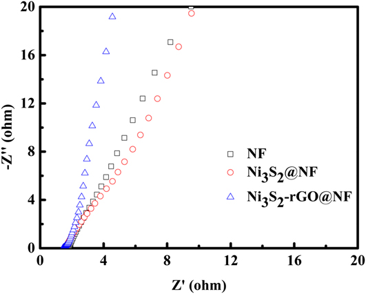
FIG. 6. Nyquist plots of the bare Ni foam, Ni3S2@NF and Ni3S2-rGO@NF electrodes.
IV. CONCLUSION
In summary, a facile one-pot hydrothermal synthesis method is developed to prepare the 3D Ni3S2-rGO@NF composite as electrocatalyst for HER. The introduction of rGO reduces the particle size of the Ni3S2, improves the conductivity of the catalyst, and increases the active sites toward HER. Because of these attributes, the 3D Ni3S2-rGO@NF electrode shows an extremely low onset potential (∼0 V versus RHE). More importantly, the cathodic current increases sharply with potential, and a robust stability is demonstrated. Our findings show that the Ni3S2-rGO@NF composite can be a highly promising candidate electrocatalyst for electrochemical hydrogen generation.
Supplementary Material
To view supplementary material for this article, please visit https://doi.org/10.1557/jmr.2017.270.
ACKNOWLEDGMENTS
This work was supported by the National Natural Science Foundation of China (Grant No. 51372080) and the Research Foundation of Education Bureau of Hunan Province, China (Grant Nos. 16C0717 and 17K039).


