


1. Introduction
Particulate transport in low-Reynolds-number fluids has broad applications in science and engineering. In earth sciences the formation of sediments, sand dunes and raindrops relies on the motion and agglomeration of fine particles and droplets from micro- to macro-scales, where hydrodynamic forces play a vital role (Happel & Brenner Reference Happel and Brenner1965; Kim & Karrila Reference Kim and Karrila1991). In biological transport the properties of cells and microstructures in body fluids are closely related to their biological functions and human health (Zuk et al. Reference Zuk, Wajnryb, Mizerski and Szymczak2014; Ishimoto Reference Ishimoto2019; Smith, Montenegro-Johnson & Lopes Reference Smith, Montenegro-Johnson and Lopes2019). In chemical and mining engineering, the behaviour and characteristics of particulate suspensions can determine flow properties of paint products and the separation of minerals (Cox & Mason Reference Cox and Mason1971; Kim Reference Kim1986). Confinement is ubiquitous in nature, and particle dynamics under confinement is important in a variety of scenarios. For instance, lab-on-a-chip devices are widely used to manipulate and sort particles, where particle–wall and particle–particle interactions mediated by hydrodynamics are crucial to the performance of these devices (Ye et al. Reference Ye, Shao, Yu and Yu2014; Hamilton et al. Reference Hamilton, Gilbert, Petrov and Ogrin2018; Kabacaoğlu & Biros Reference Kabacaoğlu and Biros2019). The migration, collision and squeezing of biological cells and capsules under confinements are relevant to cardiovascular diseases, filtration and drug delivery technologies (Leyrat-Maurin & Barthes-Biesel Reference Leyrat-Maurin and Barthes-Biesel1994; Pranay et al. Reference Pranay, Anekal, Hernandez-Ortiz and Graham2010; Lee, Long & Clarke Reference Lee, Long and Clarke2016; Barakat & Shaqfeh Reference Barakat and Shaqfeh2018; Barakat et al. Reference Barakat, Ahmmed, Vanapalli and Shaqfeh2019). Past fundamental research has considered different types of confinement, and many studies focused on particle motion near an infinite wall (Ekanayake et al. Reference Ekanayake, Berry, Stickland, Dunstan, Muir, Dower and Harvie2020; Ekanayake, Berry & Harvie Reference Ekanayake, Berry and Harvie2021), between two parallel walls (Staben, Zinchenko & Davis Reference Staben, Zinchenko and Davis2003, Reference Staben, Zinchenko and Davis2006; Griggs, Zinchenko & Davis Reference Griggs, Zinchenko and Davis2007; Swan & Brady Reference Swan and Brady2010; Pasol et al. Reference Pasol, Martin, Ekiel-Jeżewska, Wajnryb, BŁawzdziewicz and Feuillebois2011) and confined by a cylindrical wall (Shinohara & Hashimoto Reference Shinohara and Hashimoto1979; Shinohara Reference Shinohara1996; Al Quddus, Moussa & Bhattacharjee Reference Al Quddus, Moussa and Bhattacharjee2008; Vitoshkin et al. Reference Vitoshkin, Yu, Eckmann, Ayyaswamy and Radhakrishnan2016), to name a few, due to their importance in realistic applications (Happel & Brenner Reference Happel and Brenner1965). Recently, particulate transport in the low-Reynolds-number fluid under spherical or more generally total confinement draws much attention, as it underpins biological functions within living cells and droplet-based microfluidic encapsulation technologies (Aponte-Rivera & Zia Reference Aponte-Rivera and Zia2016; Skolnick Reference Skolnick2016; Aponte-Rivera, Su & Zia Reference Aponte-Rivera, Su and Zia2018; Maheshwari et al. Reference Maheshwari, Sunol, Gonzalez, Endy and Zia2019; Li et al. Reference Li, Jiang, Singh, Heinonen, Hernández-Ortiz and de Pablo2020; Gonzalez, Aponte-Rivera & Zia Reference Gonzalez, Aponte-Rivera and Zia2021; Chen & Jiang Reference Chen and Jiang2022). In biological cells the macromolecules suspended in the cytoplasmic fluid are enclosed by the cell membrane, and their confined diffusion and active motion can affect intracellular activities such as translation, transcription, signaling, cellular homeostasis and metabolism (Xiang et al. Reference Xiang, Chen, Yan, Li and Xu2020; Khoo et al. Reference Khoo, Miller, Armitage and Zhulin2022; Singh Reference Singh2022). In droplet-based microreactors made by microfluidic encapsulation techniques, confined dynamics of particles and reactants is key to suspension stability and reaction rates (Shang, Cheng & Zhao Reference Shang, Cheng and Zhao2017; Liu, Xiang & Ni Reference Liu, Xiang and Ni2020; Kim et al. Reference Kim, Wang, Yan, Zhang and Cheng2020).
Most prior experimental studies on particle dynamics and fluid flow under total confinement have focused on biological cells. Cytoplasmic streaming in cells has been suggested to enhance intracellular transport and regulate metabolism. By using magnetic resonance velocimetry, cytoplasmic streaming velocities in single living cells were measured with sufficient spatial resolution for the first time, and experimental results were in quantitative agreement with theoretical analysis (van de Meent et al. Reference van de Meent, Sederman, Gladden and Goldstein2010). To probe motor-driven stochastic properties of the cytoplasm, force spectrum microscopy was introduced to show that aggregate random forces substantially enhance motion of small proteins and large organelles, and fluctuations are larger in malignant cells than benign cells (Guo et al. Reference Guo, Ehrlicher, Jensen, Renz, Moore, Goldman, Lippincott-Schwartz, Mackintosh and Weitz2014). As one of the most fundamental processes in cells, the diffusion of macromolecules in the cytoplasm has been studied by different experimental methods including single-particle tracking, fluorescence correlation spectroscopy and fluorescence recovery after photobleaching. The diffusion coefficient of green fluorescent protein in Escherichia coli was found to be about one-tenth of that at infinite dilution in water (Elowitz et al. Reference Elowitz, Surette, Wolf, Stock and Leibler1999; Konopka et al. Reference Konopka, Shkel, Cayley, Record and Weisshaar2006).
Simulation studies have been conducted over the past decades to elucidate characteristics and mechanisms of dynamic processes confined in the cavity. By treating the cytoplasm as a continuum fluid and solving the coupled equations of Stokes flow and diffusion, it was shown that the cytoplasmic streaming in algal species can enhance internal mixing and transient response to varying external conditions, but to an extent that depends on the pitch of the helical flow (Goldstein, Tuval & van de Meent Reference Goldstein, Tuval and van de Meent2008). In a more recent work a two-phase flow model was used to study the localization of RNA/protein condensates (P granules) in germ cells, and numerical results showed that, with cytoplasmic streaming, the condensation/dissolution of P granules in the cytoplasm phase are regulated by the difference between saturation pressure and hydrodynamic pressure (Wang & Hu Reference Wang and Hu2017). To explore macromolecular diffusion, Brownian and Stokesian dynamics simulations that treat macromolecules as particles in a viscous fluid confined within a spherical cell were performed (Chow & Skolnick Reference Chow and Skolnick2015). In the simulations the particle volume fraction is 0.3 to mimic the crowded cytoplasm and the cell membrane is modelled by closely spaced wall particles. Layering of particles was observed near the wall due to steric interactions in the confined space, and confinement leads to an overall slower diffusion. Near the wall, motions of nearby particles were found to be strongly correlated and the correlations increase when hydrodynamic interactions are included.
To accurately capture the many-body hydrodynamic interactions between concentrated particles in the spherical cavity, a theoretical model that captures both the near- and far-field physics for any number of spherical particles has been developed (Aponte-Rivera & Zia Reference Aponte-Rivera and Zia2016). The model has then been utilized to study the short- and long-time diffusion of hydrodynamically interacting particles in the cavity for different particle concentrations and particle-to-cavity size ratios (Aponte-Rivera et al. Reference Aponte-Rivera, Su and Zia2018). It was found that the short-time diffusivity along the cavity radius is smaller than that tangential to the cavity wall, because of the confinement-induced anisotropy in particle mobility and spatial heterogeneity in particle concentration. At intermediate times, the mean square displacement (MSD) is anisotropic, and exhibits sub- and super-diffusive behaviours that depend on the particle-to-cavity size ratio and particle concentration. In the long-time limit the MSD reaches a plateau, and the time to reach the plateau becomes longer as the particle concentration becomes higher. Recently, the model has been extended to account for size polydispersity, and then used to study the effect of polydispersity on particle diffusion in the cavity (Gonzalez et al. Reference Gonzalez, Aponte-Rivera and Zia2021). It was shown that polydispersity makes large (small) particles diffuse slower (faster) than in the monodisperse case, and weakens hydrodynamic couplings to drive diffusivity down (up) when a large (small) particle moves further away from the wall. Confinement and polydispersity were found to induce radial de-mixing into size-segregated particles in the concentrated regime.
Single-particle dynamics in the low-Reynolds-number fluid under spherical confinement is also important, as it lays the foundation to understand more complex dynamics in concentrated suspensions. The Green's function for a spherical particle in a spherical cavity was first derived analytically (Oseen Reference Oseen1927). Later on, translation and rotation of a single sphere under spherical confinement were solved by theoretical and numerical calculations (O'Neill & Majumdar Reference O'Neill and Majumdar1970a,Reference O'Neill and Majumdarb). The mobility matrix of a spherical particle translating and rotating in a spherical cell was also evaluated from the Oseen tensor for the cavity by the Lorentz scheme (Felderhof & Sellier Reference Felderhof and Sellier2012). Recently, the aforementioned many-body model has been used to examine the effect of spherical confinement on the self-motion of a spherical particle. It was shown that the particle mobility is largest at the cavity centre and decays as the particle distance to the wall decreases. These results agree quantitatively with prior analytical results (Aponte-Rivera & Zia Reference Aponte-Rivera and Zia2016). In an earlier experiment, three-dimensional dynamics of a spherical particle confined in a spherical water globule was measured by optical microscopy (Cervantes-Martínez et al. Reference Cervantes-Martínez, Ramírez-Saito, Armenta-Calderón, Ojeda-López and Arauz-Lara2011). The short-time diffusion was shown to depend on the particle's distance to the spherical wall, and the short-time diffusivity along the tangential direction was found to be faster than along the radial direction. The effects of slip at the particle surface and cavity wall on the motion of a spherical particle in a spherical cavity were analysed via analytical methods (Keh & Lee Reference Keh and Lee2010; Faltas & Saad Reference Faltas and Saad2011; Lee & Keh Reference Lee and Keh2013). Boundary element approaches have also been used to calculate the motion of spherical and non-spherical particles in a spherical cavity (Sellier Reference Sellier2008; Chen Reference Chen2011).
Dynamics of non-spherical particles in unbounded and confined fluids also drew much attention. Near a century ago, the orientation of a neutrally buoyant ellipsoid under the shear flow was studied, and the phenomenon of Jeffery's orbits was discovered that the ellipsoidal axis moves in one of an infinite family of closed periodic orbits (Jeffery Reference Jeffery1922). The Jeffery's orbits were later extended to almost any body of revolution in any unidirectional flow, and also in a Couette viscometer (Bretherton Reference Bretherton1962). Considering rotary Brownian motion, the probability distribution function for the orientation of a neutrally buoyant axisymmetric particle in an unbounded shear flow was derived theoretically, and was applied to determine rheological properties of the dilute suspension (Hinch & Leal Reference Hinch and Leal1972; Leal & Hinch Reference Leal and Hinch1972). For two particles of arbitrary shape near contact, lubrication approximation was developed to describe their motion in a linear flow field and when they move relative to each other in an arbitrary fashion (Claeys & Brady Reference Claeys and Brady1989). The ellipsoid can also be used as a probe particle to drive the microstructure of a colloidal dispersion out of equilibrium, from which microrheological properties of the dispersion can be inferred (Khair & Brady Reference Khair and Brady2008). The translational and rotational motion of two arbitrarily oriented spheroids under the sedimentation force were determined by the method of reflections (Kim Reference Kim1985). Different from that in an unbounded fluid, a rod or spheroidal bodies sedimenting near a vertical or inclined planar wall can exhibit rotational motion; multiple modes of rotational motion were identified by experimental, theoretical and numerical studies (Russel et al. Reference Russel, Hinch, Leal and Tieffenbruck1977; Hsu & Ganatos Reference Hsu and Ganatos1989, Reference Hsu and Ganatos1994; Mitchell & Spagnolie Reference Mitchell and Spagnolie2015).
Despite significant progress, there are still questions to be answered on the single-particle dynamics in the spherical cavity. As the particle can be non-spherical in many applications, a natural question is how the particle shape affects its hydrodynamic mobility and dynamics inside the cavity. In most prior studies, the force acting on the particle is along or transverse to the particle-cavity line of centres, however, less is known on the particle motion when the applied force is not along these directions. Moreover, when biological cells and droplet-based vesicles move in their surrounding fluids, they will most likely exhibit both translational and rotational motions. The rotation of the spherical cavity will result in a rotating flow therein (Sun Reference Sun2021), and the question is how the rotating flow affects the single-particle dynamics. Lastly, the particle can be non-neutrally buoyant, and its dynamics in the rotating flow confined by the cavity remain to be explored. In this work, by using numerical simulations, we study the dynamics of a sphere, a prolate spheroid and an oblate spheroid under spherical confinement to address the above questions.
The overarching theme of this work is particle motion under external forces in a low-Reynolds-number fluid. A quiescent fluid is considered first, where particle motion parallel and perpendicular to the direction of the external force are analysed. These correspond to the mobility and drift problems, respectively. Based on understandings obtained for the quiescent fluid, we then study particle dynamics in the rotating flow. Loci where particle velocities are zero and particle trajectories are analysed to find different modes of particle motion. For each case mentioned above, effects of particle size, shape and orientation are investigated. For the rotating flow, we also consider the effect of the centrifugal/centripetal force on particle motion. The remainder of this work is organized as follows. Section 2 describes the simulation system and numerical method. Section 3 presents the main results and discussions, in which mobility, drift and particle dynamics in the rotating flow are discussed in §§ 3.1, 3.2 and 3.3, respectively. The conclusion, key take-home messages and notes on future work are given in § 4.
2. Method
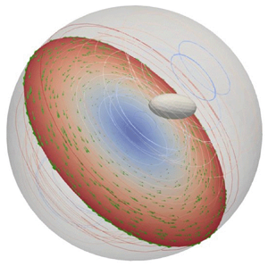
We consider a rigid particle suspended in a low-Reynolds-number fluid, confined by a spherical cavity of radius  $R_c$. The schematic of the simulation system is shown in figure 1(a). A sphere, a prolate spheroid and an oblate spheroid are considered in this work to study the effect of particle anisotropy on its confined dynamics. Aspect ratios of prolate and oblate spheroids are 2.0 and 0.5, respectively. It is assumed that the Reynolds number (
 ${\textit {Re}}=\omega R_c^2/\nu$), Stokes number (
 $Sk=\omega R_p^2/\nu$) and frequency number (
 $N_{Fr}=R_c^2/\nu t^*$) are much smaller than unity, where
  $\omega$ is the angular velocity of the cavity in rotating flow simulations,
  $\nu$ is the kinematic viscosity of the fluid,
  $R_p$ is characteristic size of the particle and
  $t^*$ is the characteristic time imposed by external forcing (Pozrikidis Reference Pozrikidis1992). Under these conditions, inertial acceleration and convective forces are much smaller than viscous forces, such that the full Navier–Stokes equations are reduced to the quasi-steady Stokes equation (Lee & Ladd Reference Lee and Ladd2007). Effects due to the inertia of the fluid, for example, the added mass effect and convective inertia, are ignored (Lavrenteva, Prakash & Nir Reference Lavrenteva, Prakash and Nir2016). Neglecting Brownian motion, the balance equation for force and torque on the particles is
 \begin{equation} m_p \frac{\mathrm{d} \boldsymbol{u}_p}{\mathrm{d} t} + 2m_p \boldsymbol{\omega} \times \boldsymbol{u}_p = \boldsymbol{F}^H + \boldsymbol{F}^{W} + \boldsymbol{F}^{C} + \boldsymbol{F}^{ext}, \end{equation}
where  $m_p$ is particle mass,
  $\boldsymbol {u}_p$ is particle velocity,
  $t$ is time,
  $\boldsymbol {F}^{H}$ is the hydrodynamic force/torque vector,
  $\boldsymbol {F}^{W}$ is the force/torque vector due to particle–wall interactions,
  $\boldsymbol {F}^{C}$ represents the centrifugal or centripetal force/torque that only applies on a non-neutrally buoyant particle in a rotating flow and
  $\boldsymbol {F}^{ext}$ contains external forces/torques. In general,
  $\boldsymbol {F}^{H}$ implicitly contains the viscous contribution, fluid acceleration
  $m_f \,\mathrm {d} \boldsymbol {u}_f / \mathrm {d} t$ and fluid Coriolis force
  $2m_f \boldsymbol {\omega } \times \boldsymbol {u}_f$, where
  $m_f=4{\rm \pi} \rho _f R_p^3 /3$ and
  $\rho _f$ is fluid density (Maxey & Riley Reference Maxey and Riley1983; Michaelides Reference Michaelides1997; Rallabandi Reference Rallabandi2021; Tsai Reference Tsai2022). As the flow is quasi-steady and
  ${\textit {Re}} \ll 1$, we neglect inertial terms in
  $\boldsymbol {F}^{H}$. Inertial terms on the left-hand side of (2.1) are of order
  $m_p \omega u_0$, which can be further written as
  $Sk (\rho _p/\rho _f) F^{ext}$. Here,
  $u_0$ is particle velocity under
  $F^{ext}$ in an unbounded fluid and
  $\rho _p$ is particle density. As
  $Sk \ll 1$, inertial terms on the left-hand side are much less than
  $F^{ext}$ if
  $\rho _p$ is not much larger than
  $\rho _f$, which is usually satisfied in common applications. Under the above conditions,
  $F^C$ and
  $F^{ext}$ can be of the same order as
  $(\rho _p-\rho _f ) R_p^3 \omega ^2 R_c \sim F^{ext}$, and (2.1) is simplified to
 \begin{equation} \boldsymbol{F}^H + \boldsymbol{F}^{W} + \boldsymbol{F}^{C} + \boldsymbol{F}^{ext} = \boldsymbol{0}. \end{equation}
In our numerical method the particle surface is discretized into a set of  $N$ nodes. To model the rigid particle and maintain particle shape, each node is connected with its neighbouring nodes by elastic springs with a large spring stiffness. The nodes are also connected with the particle centre-of-mass by stiff springs to avoid particle deformation (Zhao et al. Reference Zhao, Li, Jiang, Karpeev, Heinonen, Smith, Hernandez-Ortiz and de Pablo2017). Between surface nodes, the spring stiffness is 250 (360) for a spherical (ellipsoidal) particle; between the centre-of-mass and surface nodes, the spring stiffness is 250 (200) for a spherical (ellipsoidal) particle. Several spring stiffnesses were tested to check the sensitivity of forces on the spring stiffness. Between surface nodes, tested spring stiffnesses were 250, 300 and 360; between the centre-of-mass and surface nodes, tested spring stiffnesses were 150, 200 and 250. Results from test simulations show that the forces on the rigid particle are insensitive to the chosen spring stiffness. Discretizations of the particles considered in this work are shown in figure 1(b). Equation (2.2) is then translated into the
  $N$ surface nodes as
 \begin{equation} \boldsymbol{f}_i^H + \boldsymbol{f}_i^S + \boldsymbol{f}_i^W + \boldsymbol{f}_i^{C} + \boldsymbol{f}_i^{ext} = \boldsymbol{0}. \end{equation}
Here, 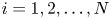 $i=1, 2,\ldots,N$,
  $\boldsymbol {f}_i^H$ is the hydrodynamic force,
  $\boldsymbol {f}_i^S$ is the spring force,
  $\boldsymbol {f}_i^W$ is the force from particle–wall interactions,
  $\boldsymbol {f}_i^C$ is the centrifugal or centripetal force and
  $\boldsymbol {f}_i^{ext}$ includes external forces. The hydrodynamic force
  $\boldsymbol {f}_i^H$ is computed implicitly in integrating the equation of motion for all nodes, which will be shown later. The spring force acting on the
  $i$th node by the
  $j$th node is
 \begin{equation} \boldsymbol{f}^S_{ij} = k\left( |\boldsymbol{r}_{ij}| - r_{0} \right) \frac{\boldsymbol{r}_{ij}}{|\boldsymbol{r}_{ij}|}, \end{equation}
where  $k$ is the spring stiffness,
  $r_0$ is the equilibrium spring length for each spring,
  $\boldsymbol {r}_{ij}=\boldsymbol {r}_i - \boldsymbol {r}_j$, and
  $\boldsymbol {r}_i$ and
  $\boldsymbol {r}_j$ are coordinates of the
  $i$th and
  $j$th nodes. The particle–wall interaction is included only in rotating flow simulations, in order to confine the particle within the cavity and prevent it from penetrating the wall. Here
  $\boldsymbol {f}_i^W$ is the negative gradient of the Lennard–Jones (LJ) potential, which is defined as
 \begin{equation} U_{LJ}(d) = 4 \epsilon \left[ \left( \frac{\sigma}{d}\right)^{12}-\left(\frac{\sigma}{d} \right)^6 \right] \end{equation}
for  $d \leqslant 2^{1/6}\sigma$, while
  $\boldsymbol {f}_i^W$ is set to zero for
  $d > 2^{1/6}\sigma$. Here,
  $d$ is the radial distance between the surface node and the wall,
  $\sigma = 0.89\bar {a}$ is set empirically such that each node has an excluded volume of radius
  $\bar {a}$, and
  $\epsilon =k_BT$ where
  $k_B$ is the Boltzmann constant and
  $T$ is the temperature (Li et al. Reference Li, Jiang, Singh, Heinonen, Hernández-Ortiz and de Pablo2020). In a rotating flow with angular velocity
  $\boldsymbol {\omega }$, the centrifugal or centripetal force is
 \begin{equation} \boldsymbol{f}_i^C = \frac{\rho_{b} V}{N}\boldsymbol{\omega} \times (\boldsymbol{\omega} \times \boldsymbol{r}_i), \end{equation}
where  $\rho _b=\rho _p-\rho _f$ is the buoyancy-corrected density and
  $V$ is the particle volume. Here
  $\boldsymbol {f}_i^C$ is centrifugal (centripetal) when
  $\rho _p > \rho _f$ (
 $\rho _p < \rho _f$). The external force is distributed on the nodes as
  $\boldsymbol {f}_i^{ext}=\boldsymbol {F}^{ext}/N$.

Figure 1. (a) Schematic of the simulation system for studying single-particle dynamics in a low-Reynolds-number fluid confined by a spherical cavity. (b) Discretizations of the sphere, prolate spheroid and oblate spheroid considered in this work. Aspect ratios of prolate and oblate spheroids are 2.0 and 0.5, respectively.
The equation of motion for all nodes on the particle surface is
 \begin{equation} \mathrm{d}\boldsymbol{R} = \left[ \boldsymbol{U}_0 + \boldsymbol{\mathsf{M}} \boldsymbol{\cdot} \boldsymbol{F} \right] \mathrm{d}t, \end{equation}
where  $\boldsymbol {R}= (\boldsymbol {r}_{1}, \boldsymbol {r}_{2},\ldots,\boldsymbol {r}_N)$ denotes a
  $3N$ vector containing nodal coordinates,
  $\boldsymbol {U}_0$ denotes a
  $3N$ vector with the undisturbed (ambient) fluid velocity at nodal positions and
  $\boldsymbol{\mathsf{M}}$ is the
  $3N \times 3N$ mobility tensor. Here
  $\boldsymbol {U}=(\boldsymbol {u}_1,\boldsymbol {u}_2, \ldots,\boldsymbol {u}_N)=\boldsymbol{\mathsf{M}}\boldsymbol{\cdot}\boldsymbol {F}$ contains
  $3N$ disturbed velocities from the hydrodynamic interaction, and
  $\boldsymbol {F}=(\boldsymbol {f}_1,\boldsymbol {f}_2,\ldots,\boldsymbol {f}_N)$ is a
  $3N$ vector including non-hydrodynamic forces on the surface nodes. The ambient and disturbed fields are solved separately as discussed later, and the ambient field corresponds to the flow in the absence of the particle. The translational and rotational motions of the rigid particle are realized by integrating (2.7) for all surface nodes, satisfying the balance equation for force and torque. The velocity field
  $\boldsymbol {U}$ driven by nodal forces
  $\boldsymbol {F}$ can be obtained by solving the Stokes equation
 \begin{equation} {-}\boldsymbol{\nabla} p+\mu \nabla ^{2} \boldsymbol{u}=-\boldsymbol{f},\quad \boldsymbol{\nabla}\boldsymbol{\cdot}\boldsymbol{u}=0, \end{equation}
where  $p$ is the fluid pressure,
  $\mu$ is the dynamic viscosity of the fluid,
  $\boldsymbol {u}$ is the fluid velocity and
  $\boldsymbol {f}(\boldsymbol {r})=\sum _{i=1}^{N} \boldsymbol {f}_i(\boldsymbol {r}_i) \delta _s(\boldsymbol {r}-\boldsymbol {r}_i)$ is the force density exerting on the fluid. To avoid singularity due to point forces placed at nodes on the particle surface, the smoothing function
  $\delta _{s}(\boldsymbol {r})$ is used to regularize the point forces, and it takes the form of a modified Gaussian function
 \begin{equation} \delta_s(\boldsymbol{r}) = \frac{\xi_s^3}{{\rm \pi}^{3/2}} \exp({-\xi_s^2 |\boldsymbol{r}|^2})\left[ \frac{5}{2} - \xi_s^2 |\boldsymbol{r}|^2 \right]. \end{equation}
The regularization parameter  $\xi _s$ is related to the characteristic node spacing on the particle surface
  $h$, i.e.
  $\xi _s\sim h^{-1}$. This is to ensure that the regularized force density is spread over the length scale of associated surface elements on the particle, preventing the fluid from penetrating the particle surface (Pranay et al. Reference Pranay, Anekal, Hernandez-Ortiz and Graham2010; Zhang, de Pablo & Graham Reference Zhang, de Pablo and Graham2012; Li et al. Reference Li, Jiang, Singh, Heinonen, Hernández-Ortiz and de Pablo2020).
Similar to Ewald methods for fast computation of long-range electrostatic interactions (Hockney & Eastwood Reference Hockney and Eastwood1988), our method exploits the linearity of the Stokes equation to split the force density in (2.8a,b) as
 \begin{equation} \boldsymbol{f}(\boldsymbol{r}) = \boldsymbol{f}_{l}(\boldsymbol{r}) + \boldsymbol{f}_{g}(\boldsymbol{r}), \end{equation}
where the local force density is
 \begin{equation} \boldsymbol{f}_{l}(\boldsymbol{r}) = \sum_{i}^{N} [ \delta_s(\boldsymbol{r}-\boldsymbol{r}_{i}) -g(\boldsymbol{r}-\boldsymbol{r}_{i}) ] \boldsymbol{f}_{i}(\boldsymbol{r}), \end{equation}
and the global force density is
 \begin{equation} \boldsymbol{f}_{g}(\boldsymbol{r}) = \sum_{i}^{N} g(\boldsymbol{r}-\boldsymbol{r}_{i}) \boldsymbol{f}_{i}(\boldsymbol{r}). \end{equation}
The screening function  $g(\boldsymbol {r})$ satisfies
  $\int _{\scriptsize \mbox {all space}}g(\boldsymbol {r})\,{\rm d}\boldsymbol {r} = 1$ and it should ensure that the contribution from the local force density to the velocity field decays exponentially. It was found that a modified Gaussian function of the type
 \begin{equation} g(\boldsymbol{r}) = \frac{\alpha^3}{{\rm \pi}^{3/2}} \exp({-\alpha^2 |\boldsymbol{r}|^2}) \left[ \frac{5}{2} - \alpha^2 |\boldsymbol{r}|^2 \right] \end{equation}
can result in an exponentially decaying local velocity field over a length scale of  $\alpha ^{-1}$, where
  $\alpha$ is the screening parameter. The typical
  $\alpha$ chosen is 0.3, and the rationalization for making this choice is that it can well-balance near-field and far-field computations of the hydrodynamic interaction, such that simulations can be performed efficiently. The local velocity field contributed from the local force density can be calculated by the Green's function approach as
 \begin{gather} \boldsymbol{u}_l(\boldsymbol{r}) = \sum_{i}^{N} \boldsymbol{\mathsf{G}}_{l}(\boldsymbol{r}-\boldsymbol{r}_i) \boldsymbol{f}_{i}, \end{gather}
 \begin{gather} \boldsymbol{\mathsf{G}}_{l}(\boldsymbol{r}) = \frac{1}{8{\rm \pi}\mu} \left[ \boldsymbol{\mathsf{I}} + \frac{\boldsymbol{rr}}{|\boldsymbol{r}|^2} \right] \left[ \frac{\mbox{erf}(\xi_s |\boldsymbol{r}|)}{|\boldsymbol{r}|} - \frac{\mbox{erf}( \alpha |\boldsymbol{r}|)}{|\boldsymbol{r}|} \right] \nonumber\\ + \frac{1}{8{\rm \pi}\mu} \left[ \boldsymbol{\mathsf{I}} - \frac{\boldsymbol{rr}}{|\boldsymbol{r}|^2} \right] \left[ \frac{2\xi_s}{\sqrt{\rm \pi}} \exp({-\xi_s^2 |\boldsymbol{r}|^2}) - \frac{2\alpha}{\sqrt{\rm \pi}} \exp({-\alpha^2 |\boldsymbol{r}|^2}) \right], \end{gather}
where  $\boldsymbol{\mathsf{I}}$ is the identity matrix (Zhang et al. Reference Zhang, de Pablo and Graham2012; Zhao et al. Reference Zhao, Li, Jiang, Karpeev, Heinonen, Smith, Hernandez-Ortiz and de Pablo2017). As
  $\boldsymbol{\mathsf{G}}_{l}$ decays exponentially on a length scale of
  $\alpha ^{-1}$, the local velocity field can be computed by only considering near neighbours of each node. On the other hand, the global velocity field,
  $\boldsymbol {u}_g(\boldsymbol {r})$, which is contributed by the global force density
  $\boldsymbol {f}_g(\boldsymbol {r})$, is calculated by solving the following Stokes equations numerically,
 \begin{equation} -\boldsymbol{\nabla} p_g+\mu \nabla^{2} \boldsymbol{u}_g =-\boldsymbol{f}_g,\quad \boldsymbol{\nabla}\boldsymbol{\cdot}\boldsymbol{u}_g =0. \end{equation}
The total fluid velocity  $\boldsymbol {u}_l+\boldsymbol {u}_g$ should satisfy proper boundary conditions of the computational domain. As the no-slip boundary condition is used for computing disturbed velocities
  $\boldsymbol{\mathsf{M}}\boldsymbol{\cdot} \boldsymbol {F}$ in (2.7), the fluid velocity at the cavity wall is
  $\bar {\boldsymbol {u}}(\boldsymbol {r_w})=\boldsymbol {0}$, where
  $\boldsymbol {r_w}$ denotes the position at the wall. As a result, the boundary condition for the global fluid velocity is
  $\boldsymbol {u}_g(\boldsymbol {r_w}) = - \boldsymbol {u}_l(\boldsymbol {r_w})$. The global velocity field is solved by the finite element method, and interpolation on the finite element grid is used to obtain values of the global velocity at nodal positions on the particle surface. For the undisturbed fluid velocity in (2.7), we set
  $\boldsymbol {U}_0 = \boldsymbol {0}$ for studying hydrodynamic mobility and drift motion of the particle in the cavity. For particle dynamics in a rotating flow,
  $\boldsymbol {U}_0$ is calculated by solving the Stokes equation (2.8a,b) with
  $\boldsymbol {f}=\boldsymbol {0}$ and the boundary condition of
  $\bar {\boldsymbol {u}}(\boldsymbol {r_w})=\boldsymbol {\omega } \times \boldsymbol {r_w}$.
The above numerical method has been validated for the sedimentation of a spherical particle between two parallel walls (Li et al. Reference Li, Jiang, Singh, Heinonen, Hernández-Ortiz and de Pablo2020). The underlying general geometry Ewald-like method has also been used to study collision and segregation behaviour of fluid-filled elastic capsules in confined simple shear flows (Pranay et al. Reference Pranay, Anekal, Hernandez-Ortiz and Graham2010; Kumar, Henríquez Rivera & Graham Reference Kumar, Henríquez Rivera and Graham2014). In the remainder of this work we will first validate the method against analytical solutions for hydrodynamic mobilities of a spherical particle confined in the spherical cavity; we will then apply it to study single-particle dynamics of a sphere, a prolate spheroid and an oblate spheroid in the cavity. For ellipsoidal particles, when we compute mobilities and drift motion, the ellipsoidal orientation is assumed to be fixed at different radial positions. Dimensionless variables are used in this study, and they are based on a set of characteristic scales. The characteristic length scale is  $\bar {a}$, the energy scale is
  $k_BT$, the force scale is
  $k_BT/\bar {a}$ and the time scale is
  $\bar {a}^2\zeta /(k_BT)$, where
  $\zeta =6{\rm \pi} \mu \bar {a}$ is the friction coefficient according to Stokes’ law.
3. Results and discussion
3.1. Mobility
We first study particle motion along the direction of the external force in a quiescent fluid, which corresponds to the mobility problem. Hydrodynamic mobility of the particle in the cavity is determined by factors such as particle position, shape and particle-to-cavity radii ratio ( $R/R_c$). We first calculate radial and transverse mobilities of the sphere with different
  $R/R_c$ in the cavity. In this work the radial (transverse) mobility means the mobility along (transverse to) the particle-cavity line of centres. The radial and transverse mobilities normalized by those in an unbounded fluid (
 $\bar {{\mathsf{M}}}_r$ and
  $\bar {{\mathsf{M}}}_t$) are presented in figure 2. For a certain
  $R/R_c$, we can see that the mobility is largest in the cavity centre and decays as the particle moves towards the wall; the transverse mobility is larger than the radial mobility at the same
  $r/R_c$ when the particle is not at the cavity centre. As
  $R/R_c$ increases, the mobility decreases because the confinement level increases and the no-slip wall has a greater influence on the particle motion. For various
  $R/R_c$, our numerical results agree well with analytical solutions (Aponte-Rivera & Zia Reference Aponte-Rivera and Zia2016) in most regions of the cavity. The analytical solutions agree very well with results by O'Neill & Majumdar (Reference O'Neill and Majumdar1970a,Reference O'Neill and Majumdarb) as shown by Aponte-Rivera & Zia (Reference Aponte-Rivera and Zia2016), so only results from Aponte-Rivera & Zia (Reference Aponte-Rivera and Zia2016) are included. We also plot results by Oseen (Reference Oseen1927) and Felderhof & Sellier (Reference Felderhof and Sellier2012) for
  $R/R_c=0.2$. They are smaller than those by Aponte-Rivera & Zia (Reference Aponte-Rivera and Zia2016) and our simulation in most regions; the accuracy for Felderhof & Sellier (Reference Felderhof and Sellier2012) becomes better near the wall. For
  $R/R_c<0.2$, these theories agree fairly well, thus, only results by Aponte-Rivera & Zia (Reference Aponte-Rivera and Zia2016) are shown. When the particle is very close to the wall, the difference between numerical and analytical results increases as the particle–wall distance decreases. For radial mobility, values of
  $r/R_c$ when the relative error becomes larger than 5 % are 0.76, 0.82, 0.87 and 0.94, respectively, which correspond to
  $R/R_c$ of 0.2, 0.15, 0.1 and 0.05; for transverse mobility,
  $r/R_c$ are 0.67, 0.76, 0.87 and 0.91. This error is caused by the usage of the regularized Green's function along with the boundary condition for
  $\boldsymbol {u}_g$ to ensure
  $\boldsymbol{\mathsf{M}} = \boldsymbol{\mathsf{M}}^T$, required by the self-adjointness of the Stokes equation, at the cost of violating the no-slip boundary condition for nodal points within
  $\sim \xi _s^{-1}$ from the wall (Hernández-Ortiz, de Pablo & Graham Reference Hernández-Ortiz, de Pablo and Graham2007). Methods that could remedy the inaccuracy to ensure that the no-slip boundary condition is simultaneously obeyed along with the self-adjointness of the Stokes equation include, but not limited to, (i) using rapidly decaying regularization functions near the wall to reduce the regularization error (Nguyen & Cortez Reference Nguyen and Cortez2014; Zhao, Lauga & Koens Reference Zhao, Lauga and Koens2019); (ii) adopting the nearest-neighbour discretization algorithm to optimize particle surface discretization (Gallagher, Choudhuri & Smith Reference Gallagher, Choudhuri and Smith2019). In rotating flow simulations that will be discussed later, a purely repulsive particle–wall interaction is applied when the particle is within a cutoff distance from the wall. The cutoff positions for different
  $R/R_c$ are marked out in figure 2. The repulsive interaction can confine the particle to be within the cavity, and also prevent it from accessing locations where the simulated dynamics would otherwise be inaccurate.

Figure 2. Normalized (a) radial and (b) transverse mobilities of the spherical particle plotted against the scaled radial position of the particle centre for four particle-to-cavity radii ratios. Solid lines are our numerical results, circles are analytical solutions by Aponte-Rivera & Zia (Reference Aponte-Rivera and Zia2016), dashed black lines are solutions by Oseen (Reference Oseen1927), the dashed red line is the solution by Felderhof & Sellier (Reference Felderhof and Sellier2012) and vertical dashed lines denote cutoff positions for particle–wall interactions included only in rotating flow simulations.
For non-spherical particles, we compute normalized radial and transverse mobilities of prolate and oblate spheroids at different radial positions in the cavity. In these calculations the particle's axis of revolution remains parallel to the particle-cavity line of centres. The radial (transverse) mobility is normalized by that parallel (transverse) to the axis of revolution in the unbounded fluid. As shown in figure 3, mobilities of prolate and oblate spheroids share the same general trend as those of the sphere: they are largest in the cavity centre and decay as particles move closer to the wall. To compare mobilities between spherical and non-spherical particles, we consider the scenario in which all particles have the same volume. The reason for this choice is that, if a deformable particle is considered, the particle shape changes during movement while its volume usually remains constant, and it is worthwhile to study how the change in shape affects particle mobility in the cavity. Figure 3(a) shows that, under different particle-to-cavity volume ratios ( $V/V_c$), the prolate spheroid has the largest radial mobility at any
  $r/R_c$ considered in this work. Near the wall, the oblate spheroid's radial mobility decreases more slowly with increasing radial position and is larger than that of the sphere. This indicates that the distance between the wall and the particle's wall-facing surface is important for the near-wall radial mobility. As the oblate spheroid's wall-facing surface is further away from the wall compared with those of others, the effect of the hydrodynamic interaction between the oblate spheroid and the wall on the particle's radial motion is weaker (see Appendix A). Figure 3(b) shows that, under different
  $V/V_c$, the oblate (prolate) spheroid has the largest (smallest) transverse mobility at any
  $r/R_c$ studied here. This result is different from that for the radial mobility (figure 3a), due to the effect of particle anisotropy. Near the wall, the prolate spheroid's transverse mobility decreases more rapidly with increasing radial position. This means that the near-wall transverse mobility is also affected by the distance between the wall and the particle's wall-facing surface. As the prolate spheroid's wall-facing surface is closer to the wall, the effect of hydrodynamic interaction between the wall and the prolate spheroid on the particle's transverse motion is stronger (see Appendix A). When
  $V/V_c$ is increased from 0.00235 to 0.008, for the radial (transverse) mobility, the difference between mobilities of the oblate (prolate) spheroid and the sphere becomes larger. It can be inferred that, increasing the confinement level has a greater influence on oblate (prolate) spheroid's radial (transverse) mobility. This is because, when moving parallel (transverse) to the axis of revolution, the oblate (prolate) spheroid's equivalent hydrodynamic radius is largest, and the confinement effect on the particle with a larger hydrodynamic radius is greater (Happel & Brenner Reference Happel and Brenner1965).

Figure 3. Normalized (a) radial and (b) transverse mobilities of prolate and oblate spheroids and the sphere plotted against the scaled radial position of the particle centre. Here  $R$ in the normalization of the mobility is the equivalent hydrodynamic radius of the unconfined spheroid. At different radial positions, the particle's axis of revolution remains parallel to the particle-cavity line of centres. For solid/dashed lines, all particles have the same particle-to-cavity volumes ratio (
 $V/V_c$).
Mobilities of non-spherical particles in the cavity are also related to particle orientation. Here, we study how the angle ( $\theta$) between the particle's axis of revolution and the particle-cavity line of centres affects radial and transverse mobilities (
 ${\mathsf{M}}_r$,
  ${\mathsf{M}}_{t1}$ and
  ${\mathsf{M}}_{t2}$) of prolate and oblate spheroids. Here
  ${\mathsf{M}}_{t1}$ is the transverse mobility that pertains to the plane formed by the particle-to-cavity line of centres and the particle's axis of revolution;
  ${\mathsf{M}}_{t2}$ is the transverse mobility perpendicular to this plane. For the spherical particle, due to the symmetry of the system,
  ${\mathsf{M}}_{t1}={\mathsf{M}}_{t2}$, and hence, only one transverse mobility is discussed; for ellipsoids,
  ${\mathsf{M}}_{t1}={\mathsf{M}}_{t2}$ only if
  $\theta$ is 0 or
  ${\rm \pi} /2$. Figures 4(a), 4(c) and 4(e) show that, for
  $0<\theta <{\rm \pi} /2$, the prolate spheroid's radial (transverse) mobility at a certain
  $r/R_c$ decreases (increases) as
  $\theta$ increases; for
  ${\rm \pi} /2<\theta <{\rm \pi}$, the trend is the opposite. Figures 4(b), 4(d) and 4(f) show that, for
  $0<\theta <{\rm \pi} /2$, the oblate spheroid's radial (transverse) mobility at a certain
  $r/R_c$ increases (decreases) as
  $\theta$ increases; for
  ${\rm \pi} /2<\theta <{\rm \pi}$, the trend is the opposite. Thus, if the magnitude of the external force is constant, the prolate (oblate) spheroid moves fastest when the force is parallel (transverse) to its axis of revolution, which agrees with the results for prolate and oblate spheroids in an unbounded fluid (Happel & Brenner Reference Happel and Brenner1965; Kim Reference Kim1985; Khair & Brady Reference Khair and Brady2008). From a physical perspective, when moving parallel (transverse) to the axis of revolution, the prolate (oblate) spheroid's disturbance on the fluid is smallest, and hence, the equivalent hydrodynamic radius and resistance of the prolate (oblate) spheroid is smallest (Happel & Brenner Reference Happel and Brenner1965). As shown in figures 4(a) and 4(b), near the cavity centre, the rate of change of
  ${\mathsf{M}}_r$ with
  $r/R_c$ is nearly independent of
  $\theta$; near the wall, the rate of change decreases (increases) as
  $\theta$ changes from 0 (
 ${\rm \pi} /2$) to
  ${\rm \pi} /2$ (
 ${\rm \pi}$). For
  ${\mathsf{M}}_{t1}$, shown in figures 4(c) and 4(d), its rate of change with
  $r/R_c$ has very weak dependence on
  $\theta$ in the entire cavity. For
  ${\mathsf{M}}_{t2}$, shown in figures 4(e) and 4(f), it is nearly independent of
  $\theta$ in the interior of the cavity; the dependence of
  ${\mathsf{M}}_{t2}$ and its rate of change with
  $r/R_c$ on
  $\theta$ becomes stronger as the ellipsoids move closer to the wall. The above observations on the variation of mobilities with
  $\theta$ are caused by the effect of particle anisotropy and confinement. At an arbitrary position, we find that the relationship between the prolate/oblate spheroid's mobilities (
 ${\mathsf{M}}_r$ and
  ${\mathsf{M}}_{t1}$) and
  $\theta$ can be fitted by sinusoidal functions as
 $$\begin{gather} {\mathsf{M}}_1(r,\theta)=\frac{1}{2}\left\{\left|{\mathsf{M}}_1(r,0)-{\mathsf{M}}_1\left(r,\frac{\rm \pi}{2}\right) \right|\sin\left(2\theta+\frac{\rm \pi}{2}\right)+{\mathsf{M}}_1(r,0)+{\mathsf{M}}_1\left(r,\frac{\rm \pi}{2}\right)\right\}, \end{gather}$$
 $$\begin{gather}{\mathsf{M}}_2(r,\theta)=\frac{1}{2}\left\{\left|{\mathsf{M}}_2(r,0)-{\mathsf{M}}_2\left(r,\frac{\rm \pi}{2}\right)\right| \sin\left(2\theta-\frac{\rm \pi}{2}\right)+{\mathsf{M}}_2(r,0)+{\mathsf{M}}_2\left(r,\frac{\rm \pi}{2}\right)\right\}, \end{gather}$$
where  ${\mathsf{M}}_1(r,\theta )$ and
  ${\mathsf{M}}_2(r,\theta )$ are radial (transverse) and transverse (radial) mobilities of the prolate (oblate) spheroid with angle
  $\theta$ at radial position
  $r$. In figures 5(a) and 5(b) we plot mobilities as a function of
  $\theta$ when
  $r/R_c=0.5$, and it is shown that numerical results agree well with those given by (3.1) and (3.2). We note that
  ${\mathsf{M}}_{t2}$ does not show a sinusoidal relationship with
  $\theta$ because it is perpendicular to the plane formed by the particle-to-cavity line of centres and the particle's axis of revolution. The dependence of all mobility components on orientation is symmetric about
  $\theta ={\rm \pi} /2$, and this symmetry corresponds to the equivalence of particle orientations for
  $\theta$ and
  ${\rm \pi} -\theta$. In figures 4 and 5 the scale for the mobility is
  $1/6{\rm \pi} \mu \bar {a}$, and the unit of the mobility depends on units of the fluid viscosity and the characteristic length chosen for the system in a particular problem.

Figure 4. Radial and transverse mobilities of (a,c,e) prolate and (b,d,f) oblate spheroids for different  $\theta$ plotted against the scaled radial position of the particle centre. Insets in (a,b,e,f) show enlarged views of the results when the particle is near the wall. The ratio of the half-length of the particle's axis of revolution to the cavity radius is 0.1.

Figure 5. (a) Prolate and (b) oblate spheroids’ radial and transverse mobilities at  $r/R_c=0.5$ plotted against
  $\theta$. The ratio of the half-length of the particle's axis of revolution to the cavity radius is 0.1.
The reason for why the orthogonal components  ${\mathsf{M}}_r$ and
  ${\mathsf{M}}_{t1}$ can be weighted by a sinusoidal function is as follows. Due to the linearity of the Stokes equation, the spheroid's radial (transverse) velocity under the radial (transverse) force
  $\boldsymbol {F}^{ext}$ is the linear superposition of radial (transverse) velocities caused by forces along (
 $\boldsymbol {F}^a$) and perpendicular to (
 $\boldsymbol {F}^p$) the spheroid's axis of revolution. Here,
  $\boldsymbol {F}^a$ and
  $\boldsymbol {F}^p$ are decompositions of
  $\boldsymbol {F}^{ext}$. When
  $\boldsymbol {F}^{ext}$ is in the radial (transverse) direction,
  $F^a = F^{ext} \cos \theta$ (
 $F^a = F^{ext} \sin \theta$) and
  $F^p = F^{ext} \sin \theta$ (
 $F^p = F^{ext} \cos \theta$). Dividing the total radial (transverse) velocity by
  $F^{ext}$, we obtain the mobility in which these trigonometric functions remain. Hence, the orthogonal components of the mobility and
  $\theta$ are related by trigonometric functions. Furthermore, due to the geometric symmetry of the spherical cavity and spheroid, the radial (transverse) mobility of the prolate spheroid is maximal (minimal) when
  $\theta$ is 0 and
  ${\rm \pi}$; the radial (transverse) mobility is minimal (maximal) when
  $\theta$ is
  ${\rm \pi} /2$. The trend is the opposite for the oblate spheroid. Based on the above analysis and observations, the orthogonal components can be weighted by a sinusoidal function.
For ellipsoid-wall hydrodynamic interactions to be reasonably represented, the expected  $r/R_c$ are computed based on the fact that the no-slip boundary condition is satisfied for nodal points from the cavity centre to
  $\sim \xi _s^{-1}=1.67$ from the wall. In figure 3, when
  $V/V_c$ is 0.00235 (0.008), the expected
  $r/R_c$ are 0.68 (0.57) and 0.80 (0.76) for prolate and oblate spheroids, respectively. In figure 4, when
  $\theta =0$, the expected
  $r/R_c$ is 0.79 for both spheroids; when
  $\theta ={\rm \pi} /2$, the expected
  $r/R_c$ are 0.84 and 0.69 for prolate and oblate spheroids, respectively. Considering errors near the wall, our observations and discussions on ellipsoidal mobility still hold.
3.2. Drift
We next consider particle motion perpendicular to the direction of the external force in a quiescent fluid, which corresponds to the drift motion. A particle can drift perpendicular to the external force near confining walls, due to the anisotropy of the mobility tensor induced by the hydrodynamic interaction between the particle and confining walls (Ganatos, Weinbaum & Pfeffer Reference Ganatos, Weinbaum and Pfeffer1982). In the work of Ganatos et al. (Reference Ganatos, Weinbaum and Pfeffer1982), the trajectory of a sphere settling under gravity in an inclined channel was studied using strong-interaction theory. In the absence of the walls, the sphere would fall vertically. In horizontal and vertical channels the sphere would also fall vertically. At other inclined angles, the sphere would exhibit both vertical and lateral drift motion. The lateral drift results from the non-isotropy of the fluid resistance tensor.
Here, we study the drift of a single particle confined in the spherical cavity. It is assumed without loss of generality that the particle is on the  $x$–
$x$– $y$ plane (
 $z=0$), which is a symmetry plane of the spherical cavity, and the external force is along positive the
  $y$ direction. We first examine the drift of the spherical particle. By relating particle velocity and the external force through the mobility, the spherical particle's main velocity (
 $U_{m}$) along the
  $y$ direction and the drift velocity (
 $U_d$) along the
  $x$ direction at any position on the
  $x$–
$x$– $y$ plane in the cavity are
 $$\begin{gather} U_m(r,\beta)=\left[{\mathsf{M}}_r(r)\sin^2\beta + {\mathsf{M}}_t(r)\cos^2\beta\right]F^{ext}, \end{gather}$$
 $$\begin{gather}U_{d}(r,\beta)=\tfrac{1}{2}\left[{\mathsf{M}}_r(r)-{\mathsf{M}}_t(r)\right]\sin(2\beta)F^{ext}, \end{gather}$$
where  $r$ and
  $\beta$ are polar coordinates of the particle centre in the symmetry plane and
  $F^{ext}$ is the magnitude of the external force. The above equations indicate that, for a certain particle-to-cavity radii ratio, the drift velocity normalized by the main velocity (
 $U_d/U_m$) does not depend on the external force, but rather depends on particle position and mobility. From (3.4), we can see that the drift occurs when
  ${\mathsf{M}}_r(r)\neq {\mathsf{M}}_t(r)$ and
  $\sin (2\alpha )\neq 0$. Figure 6(a) shows a two-dimensional distribution of
  $U_d$ on the
  $x$–
$x$– $y$ plane in the cavity for the spherical particle with
  $R/R_c=$ 0.1. It is found that
  $U_d$ is symmetric about the origin, and it is zero when the particle is on the
  $x$ or
  $y$ axis. Figure 6(b) shows the normalized drift velocity of the spherical particle with different
  $R/R_c$ as a function of
  $y/R_c$ when
  $x=-R_c/2$. We can see that, as
  $R/R_c$ increases,
  $U_d/U_m$ at a certain position generally increases. This is mainly because mobilities decrease as the confinement level increases, making the denominator
  $U_m$ smaller. Near the cavity centre,
  $U_d/U_m$ increases as
  $y/R_c$ increases because radial mobility decreases more rapidly than transverse mobility does and
  $|{\mathsf{M}}_r(r)-{\mathsf{M}}_t(r)|$ increases; very close to the wall,
  $U_d/U_m$ decreases as
  $y/R_c$ increases because transverse mobility decreases more rapidly and
  $|{\mathsf{M}}_r(r)-{\mathsf{M}}_t(r)|$ decreases. Here
  $U_d/U_m$ reaches maximum when decreasing rates of the radial and transverse mobilities with particle position are equal.

Figure 6. (a) Two-dimensional distribution of the spherical particle's drift velocity on the  $x$–
$x$– $y$ plane in the cavity. (b) Normalized drift velocity (
 $U_d/U_m$) of the spherical particle with different
  $R/R_c$ plotted against the scaled particle position in the
  $y$ direction when
  $x=-R_c/2$. Here
  $U_d$ and
  $U_m$ are drift and main velocities, respectively.
For the non-spherical particle, we choose the prolate spheroid to illustrate how particle position and angle  $\theta$ affect the drift motion. The prolate spheroid's centre is varied along the radial direction, and
  $\theta$ is varied from 0 to
  $11{\rm \pi} /12$ with an interval of
  ${\rm \pi} /12$ at each position. For every configuration, external forces along positive radial and transverse directions are applied, respectively. Here, the positive radial direction points from the cavity centre to the wall; the positive transverse direction, being perpendicular to the radial direction, points counterclockwise in the symmetry plane formed by the cavity centre and the axis of revolution of the prolate spheroid. We compute normalized drift velocities in different cases, and results are presented in figure 7. Figures 7(a) and 7(b) show that, when
  $\theta$ is 0 or
  ${\rm \pi} /2$, the drift velocity is zero. When
  $\theta$ takes other values and the principle axes of the prolate spheroid do not align with the particle-cavity line of centres, particle anisotropy breaks the symmetry of the system configuration and the particle–wall hydrodynamic interaction, causing the drift motion to occur. The particle drifts along the transverse (radial) direction when the external force is along the radial (transverse) direction. For
  $\theta <{\rm \pi} /2$ (
 $\theta >{\rm \pi} /2$), the drift velocity is positive (negative). As
  $\theta$ increases,
  $|U_d/U_m|$ increases when
  $0<\theta <{\rm \pi} /4$ and
  ${\rm \pi} /2<\theta <3{\rm \pi} /4$; the trend is the opposite when
 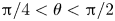 ${\rm \pi} /4<\theta <{\rm \pi} /2$ and
  $3{\rm \pi} /4<\theta <{\rm \pi}$. Here
  $|U_d/U_m|$ reaches maximum when
  $\theta ={\rm \pi} /4$ and
  $3{\rm \pi} /4$. When the external force is in the radial direction, the rate of change of
  $U_d/U_m$ with
  $\theta$ is weakly dependent on
  $r/R_c$ near the cavity centre; the dependency becomes stronger near the wall. When the external force is in the transverse direction, the rate of change of
  $U_d/U_m$ with
  $\theta$ is nearly independent of
  $r/R_c$ in the entire cavity.

Figure 7. Normalized drift velocity ( $U_d/U_m$) of the prolate spheroid along the (a) transverse and (b) radial directions plotted against the scaled radial position of the particle centre;
  $U_d/U_m$ along the (c) transverse and (d) radial directions plotted against
  $\theta$. In (c,d) results from the simulation and (3.5) are for
  $r/R_c=0.5$. The external force is along the positive (a,c) radial and (b,d) transverse direction, respectively. The ratio of the half-length of the prolate spheroid's axis of revolution to the cavity radius is 0.1.
In figures 7(c) and 7(d) we plot the normalized drift velocity along the transverse and radial directions as a function of  $\theta$ when
  $r/R_c=0.5$. It is found that the normalized drift velocity and
  $\theta$ show a sinusoidal relationship. We define
  $\bar {U} = U_d/U_m$ and it can be expressed as
 \begin{equation} \bar{U}(r,\theta)=\frac{1}{2} \left[\bar{U}\left(r,\frac{\rm \pi}{4}\right)-\bar{U}\left(r,\frac{3{\rm \pi}}{4}\right) \right]\sin(2\theta) , \end{equation}
which holds for drift motion in either the radial or transverse direction at any radial position. Numerical results in figures 7(c) and 7(d) agree well with those given by (3.5). Drift velocities of the prolate spheroid in an unbounded fluid are also calculated analytically (Happel & Brenner Reference Happel and Brenner1965; Kim Reference Kim1985). Comparing results at the same  $\theta$, we can see that the absolute magnitude of drift velocity inside the cavity is higher than that in an unbounded fluid, indicating that the confinement enhances drift motion of the spheroid. Lastly, similar to the case in figure 6, we place the prolate spheroid's centre in the
  $x$–
$x$– $y$ plane (
 $z=0$) and apply an external force in the
  $y$ direction on the particle. The prolate spheroid's main velocity along the
  $y$ direction and the drift velocity along the
  $x$ direction at any position can be, on the basis of (3.3) and (3.4), computed by
 \begin{align} U_m(r,\beta,\theta) & = \left\{{\mathsf{M}}_r(r,\theta)\sin^2\beta+ {\mathsf{M}}_t(r,\theta)\cos^2\beta \right.\nonumber\\ &\quad\left. +\tfrac{1}{2}\left[{\mathsf{M}}_t(r,\theta)\bar{U}_r(r,\theta)+ {\mathsf{M}}_r(r,\theta)\bar{U}_t(r,\theta)\right]\sin(2\beta)\right\} F^{ext}, \end{align}
 \begin{align} U_d(r,\beta,\theta) & = \left\{\tfrac{1}{2}\left[ {\mathsf{M}}_r(r,\theta)-{\mathsf{M}}_t(r,\theta)\right]\sin(2\beta) \right.\nonumber\\ &\quad \left. + {\mathsf{M}}_t(r,\theta)\bar{U}_r(r,\theta)\cos^2\beta - {\mathsf{M}}_r(r,\theta)\bar{U}_t(r,\theta)\sin^2\beta \right\}F^{ext}, \end{align}
where  $\bar {U}_r(r,\theta )$ and
  $\bar {U}_t(r,\theta )$ are the normalized drift velocity in the radial and transverse directions given by (3.5). From (3.6) and (3.7), we can see that, when
  $\beta$ and
  $\theta$ are not 0 or
  ${\rm \pi} /2$, the main velocity along the
  $y$ direction of the non-spherical particle is also affected by the drift motion, which is not observed for the spherical particle.
3.3. Rotating flow
In previous sections we have discussed particle motion under external forces in a quiescent low-Reynolds-number fluid confined by the spherical cavity, which forms the basis for studying more complex behaviour. In many applications, droplets and cells can exhibit both translational and rotational motion. The rotational motion can induce a rotating flow in the cavity, leading to more complex particle dynamics. To study how the rotating flow affects single-particle dynamics in the cavity, we consider the spherical cavity that rotates about the the  $x$ axis with angular velocity
  $\boldsymbol {\omega }$. External forces acting on the particle include a rotation-induced centrifugal or centripetal force, depending on the sign of the buoyancy-corrected density, and a constant external force.
3.3.1. Loci for zero particle velocities
The reason for calculating loci for zero radial and tangential velocities is to determine the stagnation point for the particle motion where the two loci intersect. Prior work by Lee & Ladd (Reference Lee and Ladd2007) is related to this calculation, where loci for the point particle in a rotating low-Reynolds-number fluid are determined. In this work we consider finite-size particles confined in the spherical cavity to explore effects of particle size, shape and confinement on the loci and stagnation points. If particle–wall hydrodynamic interaction is not considered, velocities of a spherical particle in the cavity can be expressed as
 $$\begin{gather} U_r=(F^c-F^{ext}\sin\beta)\zeta_p^{-1}, \end{gather}$$
 $$\begin{gather}U_t=\omega r-(F^{ext}\cos\beta)\zeta_p^{-1}, \end{gather}$$
where  $U_r$ and
  $U_t$ denote the radial and tangential velocity of the particle, respectively,
  $\boldsymbol{F}^{ext}$ is in the negative
  $z$ direction and
  $\zeta _p=6{\rm \pi} \mu R$ is the friction coefficient of the particle. Here, positive values of
  $U_r$ and
  $F^c$ mean that the direction of radial velocity is from the origin to the wall and the force is centrifugal; positive values of
  $U_t$ and
  $\omega$ mean the tangential velocity of the particle and angular velocity of the cavity are counterclockwise. If particle–wall hydrodynamic interaction is considered and the particle centre is in the
  $y$–
$y$– $z$ plane at
  $x=0$, velocities of the spherical particle are
 $$\begin{gather} U_r=\bar{{\mathsf{M}}}_r(r) (F^c - F^{ext}\sin\beta ) \zeta_p^{-1}, \end{gather}$$
 $$\begin{gather}U_t=\omega r-[\bar{{\mathsf{M}}}_t(r) F^{ext}\cos\beta] \zeta_p^{-1}. \end{gather}$$
Solving for  $U_r=0$ and
  $U_t=0$ (Lee & Ladd Reference Lee and Ladd2007), we obtain two loci
  $C_r$ and
  $C_t$. It is found that the two loci always intersect in the cavity regardless of non-zero parameters (
 $\omega$,
  $\rho _b$,
  $V$ and
  $F^{ext}$) in (3.10) and (3.11), while the stagnation point's location depends on these parameters. We note that there is only one stagnation point (not the cavity centre).
We first study how the confinement level  $R/R_c$ affects
  $C_r$ and
  $C_t$, and results are shown in figure 8. Radial positions in the figure are scaled by the maximal radial position determined from (3.8) and (3.9). Parameters used in the computations are
  $F^{ext}=-10$,
  $\rho _b V=1$ and
  $\omega =1$. We can see that
  $C_r$ remains the same for different
  $R/R_c$, and it is independent of the confinement-induced mobility heterogeneity and the confinement level. On the contrary,
  $C_t$ shrinks notably as
  $R/R_c$ increases, and the stagnation point becomes closer to the cavity centre. This indicates that the confinement level is important for determining locations where the particle's tangential velocity is zero, which in turn affects the stagnation point's location and particle motion in the rotating flow. It is also observed that
  $C_t$ is a circle in the unbounded case; however, for other
  $R/R_c$,
  $C_t$ is not exactly circular, which is due to the mobility heterogeneity induced by the confining wall of the cavity.

Figure 8. (a) Lines for  $U_r=0$ (dashed) and
  $U_t=0$ (solid) under different
  $R/R_c$. (b) Lines for
  $U_t=0$ in planes parallel to the
  $y$–
$y$– $z$ plane at different
  $x$ for the spherical particle with
  $R/R_c=0.05$. Here
  $\boldsymbol {F}^{ext}$ is in the negative
  $z$ direction.
When the spherical particle's centre is in other planes parallel to the  $y$–
$y$– $z$ plane at
  $x=0$, its in-plane mobility at the same
  $y$ and
  $z$ positions in the cavity varies as the
  $x$ position changes, resulting in different
  $C_t$ on each plane. Figure 8(b) shows
  $C_t$ in these planes at different
  $x$ positions. It is observed that the difference between neighbouring
  $C_t$ is more pronounced for
 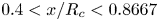 $0.4< x/R_c<0.8667$ than that for
  $x/R_c<0.4$. This is because, when the particle is closer to the wall, the confinement effect becomes more significant and the mobility varies more notably. As
  $x$ increases,
  $C_t$ shrinks and the stagnation point becomes closer to the
  $x$ axis.
For the non-spherical particle whose centre is in the  $y$–
$y$– $z$ plane at
  $x=0$,
  $C_r$ is the same as that for the spherical particle, if the centrifugal or centripetal force and external force remain the same. This is because
  $C_r$ is independent of the mobility. However,
  $C_t$ for the non-spherical particle is different from that for the spherical particle, even if the forces are the same, because
  $C_t$ depends on the mobility and mobilities between spherical and non-spherical particles are different as shown in previous sections. To calculate
  $C_t$ for the non-spherical particle, one needs to consider particle orientation as it also affects the mobility and, hence,
  $C_t$. At a certain position, the non-spherical particle's orientation can vary in the rotating flow, so we use maximal and minimal transverse mobilities at the position to determine a region where
  $U_t$ can be zero as shown in figure 9. We can see that the area enclosed by
  $C^{min}_t$ (minimal transverse mobility used) is smaller than that by
  $C^{max}_t$ (maximal transverse mobility used). Hence, the stagnation point for the non-spherical particle also depends on particle orientation.

Figure 9. Regions (transparent purple) where  $U_t$ can be zero for (a) prolate and (b) oblate spheroids. The ratio of the half-length of the particle's axis of revolution to cavity radius is 0.2. Here
  $\boldsymbol {F}^{ext}$ is in the negative
  $z$ direction.
Depending on the sign of  $\rho _b$, the stagnation point can be stable (
 $\rho _b<0$) or metastable (
 $\rho _b>0$). For both
  $\rho _b<0$ and
  $\rho _b>0$, if the particle is at the stagnation point, it will stay there unless new external forces perturb its motion. When
  $\rho _b>0$, if the particle position deviates from the stagnation point by a small amount, the particle will gradually move away from this point. When
  $\rho _b<0$, no matter how far the particle is away from the stagnation point, it will gradually move closer to and eventually arrive at the point. Details of the two modes of motion will be discussed in the following subsections.
3.3.2. Motion of the spherical particle
We further study trajectories of the spherical particle released at three different positions in the  $y$–
$y$– $z$ plane at
  $x=0$ in the spherical cavity, and results are shown in figure 10. Here, the particle-to-cavity radii ratio is 0.05,
  $F^{ext}=-10$ (
 $\boldsymbol {F}^{ext}$ is in the negative
  $z$ direction),
  $\vert \rho _b V\vert =0.357$ and
  $\omega =1$. In Appendix B, we plot the temporal evolution of various force contributions along a typical trajectory, and validate the approximation of neglecting inertial terms on the left-hand-side of equation (2.1). When
  $F^c$ is centrifugal (figure 10a), particles released at different positions eventually evolve into the same stable orbit, moving counterclockwise along it periodically. Part of the stable orbit is along the cavity wall and particle velocity in this part is relatively small because the particle moves against
  $F^{ext}$; the rest of the stable orbit is in the interior of the cavity and the particle velocity is higher as directions of particle motion and
  $F^{ext}$ are the same. In this case,
  $C_t$ does not intersect with the wall and there are no stagnation points at the wall. When the initial position is very close to the stagnation point (blue dots in figure 10a), the particle initially rotates very slowly around the stagnation point and then moves faster and faster until it collides with the wall (see supplementary movie 1 available at https://doi.org/10.1017/jfm.2023.572). When
  $F^c$ is centripetal (figure 10b), particles released at different positions finally focus at the stagnation point where
  $C_r$ and
  $C_t$ intersects (see supplementary movie 2). We also analysed particle trajectories under the centrifugal force when initial positions are not in the
  $y$–
$y$– $z$ plane at
  $x=0$. The particle is released at three different positions in the plane at
  $x=10$ parallel to the
  $y$–
$y$– $z$ plane. As shown in figure 11, after a certain amount of time, trajectories in all cases exhibit the same pattern and become almost the same. For initial positions at
  $(10,4,2.5)$ and
  $(10,5,0)$, the time for trajectories to converge is shorter, as the two positions are relatively close to each other. For the initial position at
  $(10,-7.5,0)$, the time for its trajectory to become nearly the same as the others is longer. After being released, the particle moves within the plane at
  $x=10$. When it attaches to the wall, the repulsive force from the wall pushes the particle towards the
  $y$–
$y$– $z$ plane at
  $x=0$, and its
  $x$ position decreases. However, when the particle detaches the wall (see figure 10a), its
  $x$ position stops changing and the particle rotates in the plane determined by the location where the particle detaches from the wall (see supplementary movie 3). Thereafter, the particle attaches and detaches from the wall in a similar manner periodically until it reaches the
  $y$–
$y$– $z$ plane at
  $x=0$. Differences between trajectories after they exhibit the same pattern and marginal motion in the positive
  $x$ direction before the particle attaches to the wall are observed, which could be caused by the drift motion discussed in the previous section.

Figure 10. (a) Trajectories of spherical particles released at three positions  $r_0=(0,-7.5,0)$,
  $r_0=(0,9,4.3)$ and
  $r_0=(0,5,7)$ under the centrifugal force. (b) Trajectories of spherical particles released at three positions
  $r_0=(0,-7.5,0)$,
  $r_0=(0,5,0)$ and
  $r_0=(0,0,0)$ under the centripetal force. Here
  $\boldsymbol {F}^{ext}$ is in the negative
  $z$ direction.

Figure 11. Projection of particle trajectories in the (a)  $x$–
$x$– $y$ plane and (b)
  $x$–
$x$– $z$ plane under the centrifugal force. The spherical particle's initial positions are
  $r_0=(10,-7.5,0)$,
  $r_0=(10,4,2.5)$ and
  $r_0=(10,5,0)$, respectively. We denote by
  $\leftarrow$ motion in the negative
  $x$ direction. Here
  $\boldsymbol {F}^{ext}$ is in the negative
  $z$ direction.
We further study trajectories of the spherical particle in the rotating flow when the external force contains both  $x$ and
  $z$ components (
 $F_x$ and
  $F_z$). Here, the particle can cross planes parallel to the
  $y$–
$y$– $z$ plane in the interior of the cavity, leading to different particle dynamics compared with those discussed in the previous paragraph. Figure 12 shows projection of particle trajectories in the
  $x$–
$x$– $y$ and
  $y$–
$y$– $z$ planes under centrifugal and centripetal forces. We consider
  $F_x=-1$ and
  $F_x=-5$, respectively;
  $F_z=-10$ is the same as
  $F^{ext}$ used in rotating flow simulations mentioned earlier. Here
  $\boldsymbol {F}_{x}$ and
  $\boldsymbol {F}_{z}$ are in the negative
  $x$ and
  $z$ directions, respectively. Figure 12(a) shows that, when
  $F^c$ is centrifugal and
  $F_x=-1$, the particle initially migrates towards the negative
  $x$ direction. For
  $x>0$, the magnitude of the particle velocity when the particle attaches to the wall is larger than that when the particle detaches from the wall. This is because, when
  $x>0$ and the particle attaches to the wall, the
  $x$ component of the force due to particle–wall interactions and
  $F_x$ are in the same direction and the magnitude of the total force is larger. For
  $x<0$, the
  $x$ component of the force due to particle–wall interactions is in the positive
  $x$ direction and is larger than
  $|F_x|$, so the particle migrates towards the positive
  $x$ direction when it attaches to the wall; when the particle detaches from the wall, it migrates again in the negative
  $x$ direction under the action of
  $F_x$. Eventually, the particle moves back and forth along the
  $x$ and
  $y$ directions periodically in a stable orbit (see supplementary movie 4), because
  $F_x$ alternates in sign and the rotating flow causes alternating particle motion along the
  $y$ direction. In the
  $y$–
$y$– $z$ plane as shown in figure 12(b), initially the region that the particle trajectory spans becomes wider, because the particle moves closer to the
  $y$–
$y$– $z$ plane; the region then shrinks as the particle moves away from the
  $y$–
$y$– $z$ plane. When
  $F_x=-5$ and
  $F^c$ remains centrifugal, the particle initially migrates faster towards the negative
  $x$ direction because
  $|F_x|$ becomes larger; the particle eventually stays at a stagnation point near the wall (see figure 12c,d), where the centrifugal force, external force and the force due to particle–wall interactions balance each other (see supplementary movie 5). Figures 12(e)–12(h) show that, under the centripetal force, the particle migrates in the negative
  $x$ direction, and eventually stays at a stagnation point regardless of the magnitude of
  $F_x$. As
  $|F_x|$ increases, the stagnation point moves further towards the negative
  $x$ direction, because stronger force in the positive
  $x$ direction due to particle–wall interactions is needed to balance
  $F_x$. It is also found that, the overall pattern of particle trajectories under the centripetal force is similar to that under the centrifugal force shown in figures 12(c) and 12(d). The above results indicate that the interplay between the external force, centrifugal or centripetal force and the force from particle–wall interactions can give rise to complex particle dynamics in the rotating flow confined by the spherical cavity.

Figure 12. Projection of particle trajectories in the (a,c,e,g)  $x$–
$x$– $y$ and (b,d,f,h)
  $y$–
$y$– $z$ planes for the spherical particle with
  $R/R_c=0.05$. The red circle is the initial particle position
  $r_0=(10, 6, 0)$. (a–d) Centrifugal and (e–h) centripetal forces are considered, respectively. External forces in the
  $x$ direction are (a,b,e,f)
  $F_x=-1$ and (c,d,g,h)
  $F_x=-5$, respectively; the external force in the
  $z$ direction is
  $F_z=-10$. Here
  $\boldsymbol {F}_{x}$ and
  $\boldsymbol {F}_{z}$ are in the negative
  $x$ and
  $z$ directions. We denote by
  $\leftarrow$ motion in the negative
  $x$ direction.
3.3.3. Motion of ellipsoidal particles
For the spherical particle, the centrifugal or centripetal force does not induce a torque on the particle because the particle is symmetric about the plane where its centre moves. However, for the non-spherical particle, when it is not symmetric about the plane where its centre moves, the centrifugal or centripetal force can induce a torque on it. We note that, as the external force is assumed to be uniformly distributed on the particle, the direction and magnitude of  $\boldsymbol {f}_i^{ext}$ are the same for all surface nodes. Consequently, the external force does not induce a torque on the particle.
To calculate the torque due to centrifugal/centripetal force, two Cartesian coordinate systems are used: one is the normal  $o$-
$o$- $xyz$ coordinate system and the other one is fixed on the particle (
 $o'$-
$o'$- $x'y'z'$) as shown in figure 1(a). For any point in the particle, the coordinate transformation is
 \begin{equation}
\left[\begin{array}{@{}c@{}} x \\ y\\ z
\end{array}\right]= \boldsymbol{\mathsf{A}}
\left[ \begin{array}{@{}c@{}} x' \\ y' \\ z'
\end{array}\right] + \left[ \begin{array}{@{}c@{}} x_0 \\
y_0 \\ z_0 \end{array}\right],
\end{equation}
\begin{equation}
\left[\begin{array}{@{}c@{}} x \\ y\\ z
\end{array}\right]= \boldsymbol{\mathsf{A}}
\left[ \begin{array}{@{}c@{}} x' \\ y' \\ z'
\end{array}\right] + \left[ \begin{array}{@{}c@{}} x_0 \\
y_0 \\ z_0 \end{array}\right],
\end{equation}
where ( $x_0, y_0, z_0$) is the coordinate of the particle centre in the
  $o$-
$o$- $xyz$ coordinate system, and the matrix
  $\boldsymbol{\mathsf{A}}$ is
 \begin{equation}
\boldsymbol{\mathsf{A}} =\left[\begin{array}{@{}ccc@{}}
\cos a_1 & \cos b_1 & \cos c_1 \\ \cos a_2 & \cos b_2 &
\cos c_2 \\ \cos a_3 & \cos b_3 & \cos c_3
\end{array}\right],
\end{equation}
\begin{equation}
\boldsymbol{\mathsf{A}} =\left[\begin{array}{@{}ccc@{}}
\cos a_1 & \cos b_1 & \cos c_1 \\ \cos a_2 & \cos b_2 &
\cos c_2 \\ \cos a_3 & \cos b_3 & \cos c_3
\end{array}\right],
\end{equation}
where  $a_1$,
  $a_2$ and
  $a_3$ are angles between the
  $x'$ axis and the
  $x$,
$x$,  $y$ and
  $z$ axes;
  $b_1$,
  $b_2$ and
  $b_3$ are angles between the
  $y'$ axis and the
  $x$,
$x$,  $y$ and
  $z$ axes;
  $c_1$,
  $c_2$ and
  $c_3$ are angles between the
  $z'$ axis and the
  $x$,
$x$,  $y$ and
  $z$ axes. As the cavity rotates about the
  $x$ axis, the centrifugal or centripetal force on an infinitesimal volume in the particle is
 \begin{equation} \mathrm{d}\boldsymbol{F^c} = \rho_b \omega^2 \left[\begin{array}{@{}c@{}} 0 \\ x'\cos a_2+ y'\cos b_2 +z'\cos c_2 +y_0\\ x'\cos a_3+ y'\cos b_3 +z'\cos c_3 +z_0 \end{array}\right]\mathrm{d}V. \end{equation}
By volume integration, the torque on the particle is
 \begin{equation} \boldsymbol{T_c}= \int_V \boldsymbol{s} \times \,\mathrm{d}\boldsymbol{F^c}, \end{equation}
where  $\boldsymbol {s}$ is the vector from the infinitesimal volume to the particle centre
 \begin{equation} \boldsymbol{s} = \boldsymbol{\mathsf{A}} \left[ \begin{array}{@{}c@{}} x' \\ y' \\ z' \end{array}\right]. \end{equation}
Performing the integration in (3.15), we obtain the torque as
 \begin{equation} \boldsymbol{T_c}= \frac{4{\rm \pi}}{15} \rho_b \omega^2 abc \left[\begin{array}{@{}c@{}} 0 \\ -a^2\cos a_1 \cos a_3 -b^2\cos b_1 \cos b_3 -c^2\cos c_1 \cos c_3 \\ a^2\cos a_1 \cos a_2 +b^2\cos b_1 \cos b_2 +c^2\cos c_1 \cos c_2 \end{array}\right], \end{equation}
where  $a$,
$a$,  $b$ and
  $c$ are half-lengths of three principal axes of the ellipsoidal particle in the
  $x'$,
$x'$,  $y'$ and
  $z'$ directions, respectively. It can be seen from (3.17) that, under certain
  $\rho _b$ and
  $\omega$, the torque depends on geometric properties of the ellipsoidal particle, such as the lengths of the principal axes and orientation. We note that the torque does not depend on particle location, which is only true for the torque due to centrifugal/centripetal force, but not for other general torques on the particle.
Lastly, we study how the torque affects orientations of prolate and oblate spheroids. The particle centre is initially at  $r_0=(0, 9.3, 4)$, and
  $\boldsymbol {F}^{ext}$ is in the negative
  $z$ direction. Under the centrifugal force, temporal evolutions of angles between the
  $x'$ axis and the
  $x$,
$x$,  $y$ and
  $z$ axes (
 $a_1$,
  $a_2$ and
  $a_3$) are analysed for different initial particle orientations. Results for the prolate spheroid are presented in figure 13(a–d), and results for the oblate spheroid are given in figures 13(e) and 13(f). Figures 13(a) and 13(d) show that the angle
  $a_1$ remains almost constant during particle motion. This is because, in these two cases, the particle is symmetric about the
  $y$–
$y$– $z$ plane and
  $\boldsymbol {T_c}$ is zero. For figure 13(a), the
  $x'$ axis is perpendicular to the
  $y$ and
  $z$ axes; for figure 13(d), the
  $x'$ axis is perpendicular to the
  $x$ axis and it rotates as the particle moves with the flow, resulting in periodic variations of
  $a_2$ and
  $a_3$. From figures 13(b) and 13(c), we can see that, when the initial particle orientation deviates from that in figure 13(a),
  $a_1$ increases for a certain amount of time and then decreases sharply (see supplementary movie 6). The increase of
  $a_1$ is due to
  $\boldsymbol {T_c}$, while the decrease of
  $a_1$ is due to a particle–wall collision. The above results indicate that, for the prolate spheroid, particle orientation in figure 13(a) is in a metastable state, while
  $a_1={\rm \pi} /2$ (figure 13d and supplementary movie 7) is in a stable state. If
  $a_1$ deviates from 0 (even by a small amount), it will keep rising towards
  ${\rm \pi} /2$ unless the particle collides with the wall. For the oblate spheroid, when the initial particle orientation is the same as that in figures 13(a) or 13(d), temporal evolutions of the angles are almost the same as those of the prolate spheroid, because the oblate spheroid is also symmetric about the
  $y$–
$y$– $z$ plane. However, when the initial particle orientation is the same as that in figures 13(b) or 13(c), temporal evolutions of the angles are different from those of the prolate spheroid (see supplementary movie 8). In the beginning,
  $a_1$ remains nearly constant and then decreases under the action of
  $\boldsymbol {T_c}$. At
  $t=0.2$,
  $a_1$ increases sharply to
  ${\rm \pi} /2$ due to particle–wall collisions. During particle motion along the wall,
  $a_1$ remains as
  ${\rm \pi} /2$, because the particle–wall interaction dominates and prevents
  $\boldsymbol {T_c}$ changing
  $a_1$. When the particle detaches from the wall,
  $\boldsymbol {T_c}$ becomes dominant again, so
  $a_1$ increases and the
  $x'$ axis tends to be parallel to the
  $x$ axis. We find that, for the oblate spheroid,
  $a_1=0$ and
  $a_1={\rm \pi} /2$ are in stable and metastable states, respectively. They are different from those for the prolate spheroid, because torques for prolate and oblate spheroids considered here are opposite in sign. For both prolate and oblate spheroids, in their stable orbits, as they move in the interior of the cavity and along the wall alternatively and periodically, the torque and particle–wall collision compete against each other, leading to nonlinear variations of particle orientation.

Figure 13. Angles between the  $x'$ axes of (a–d) prolate and (e,f) oblate spheroids and
  $x$,
$x$,  $y$ and
  $z$ axes plotted against time under the centrifugal force. Initial particle orientations are (a)
  $a_1=0$,
  $a_2=a_3={\rm \pi} /2$; (b,e)
  $a_1={\rm \pi} /6$,
  $a_2={\rm \pi} /2$,
  $a_3=2{\rm \pi} /3$; (c,f)
  $a_1={\rm \pi} /3$,
  $a_2={\rm \pi} /2$,
  $a_3=5{\rm \pi} /6$ and (d)
  $a_1=a_2={\rm \pi} /2$,
  $a_3={\rm \pi}$. The ratio of the half-length of the prolate (oblate) spheroid's axis of revolution to the cavity radius is 0.0794 (0.0315). Here
  $\boldsymbol {F}^{ext}$ is in the negative
  $z$ direction.
Due to the repulsive force and the entropic barrier near the wall, there exists a region very close to the wall that is inaccessible to the particles (Sunol & Zia Reference Sunol and Zia2023). If the particles are allowed to access this region, we expect that particle motion under the centrifugal force will be quantitatively different, but qualitative behaviour will remain unchanged. Quantitatively, particle motion along the wall will be faster without the repulsive force. This is because the mobility in this region is lower, and particle velocity due to the external force, which in our cases counteracts particle motion due to the rotating flow, becomes smaller. As a result, the timing of collisions with the wall and the duration for particles being attached to the wall will change. There will also exist minor changes in locations where the particles attach/detach from the wall. As these locations only change marginally, the spheroid's orientation and repulsive force at the point of collision will remain almost the same, leading to the same qualitative behaviour.
Under the centripetal force, motion of the non-spherical particle is different from that under the centrifugal force. Figure 14 shows temporal evolutions of angles  $a_1$,
  $a_2$ and
  $a_3$ under the centripetal force for different initial particle orientations. In the parameter space of this work, there is no particle–wall collision in the centripetal case and the wall does not affect particle orientation. For the prolate spheroid (figure 14a,b), under the action of
  $\boldsymbol {T_c}$,
  $a_1$ gradually decreases to 0;
  $a_2$ and
  $a_3$ oscillates around
  ${\rm \pi} /2$ and the oscillation amplitude gradually decreases to 0 (see supplementary movie 9). We find that
  $a_1=0$ (
 $a_1={\rm \pi} /2$) is in a stable (metastable) state for the prolate spheroid under the centripetal force. For the oblate spheroid (figure 14c,d),
  $a_2$ and
  $a_3$ also oscillate around
  ${\rm \pi} /2$, but the oscillation amplitude gradually increases to
  ${\rm \pi}$ (see supplementary movie 10). The overall trend for
  $a_1$ is increasing towards
  ${\rm \pi} /2$, while
  $a_1$ also oscillates under the action of
  $\boldsymbol {T_c}$. Stable and metastable states for the oblate spheroid under the centripetal force are found to be
  ${\rm \pi} /2$ and 0, respectively, which are opposite to those for the prolate spheroid because
  $\boldsymbol {T_c}$ for prolate and oblate spheroids are opposite in sign. It is also found that stable and metastable states for the orientation of the same ellipsoidal particle under the centripetal force are opposite to those under the centrifugal force, because
  $\boldsymbol {T_c}$ under centrifugal and centripetal forces are opposite in sign.

Figure 14. Angles between the  $x'$ axes of (a,b) prolate and (c,d) oblate spheroids and
  $x$,
$x$,  $y$ and
  $z$ axes plotted against time under the centripetal force. Initial particle orientations are (a,c)
  $a_1={\rm \pi} /6$,
  $a_2={\rm \pi} /2$,
  $a_3=2{\rm \pi} /3$ and (b,d)
  $a_1={\rm \pi} /3$,
  $a_2={\rm \pi} /2$,
  $a_3=5{\rm \pi} /6$. The ratio of the half-length of the prolate (oblate) spheroid's axis of revolution to the cavity radius is 0.0794 (0.0315). The vertical dotted line denotes the time when the distance between the particle centre and the stagnation point is 0.1. Here
  $\boldsymbol {F}^{ext}$ is in the negative
  $z$ direction.
The above results share similar features with classical results for an ellipsoid in an unbounded fluid or near a flat wall, while there are also differences between them. When the ellipsoid is away from the cavity wall, its motion at stable and metastable states are similar to the tumbling and log-rolling motion in Jeffery's and Bretherton's orbits (Jeffery Reference Jeffery1922; Bretherton Reference Bretherton1962). Deviation from the normal tumbling motion occurs when the ellipsoid attaches and moves along the wall, due to the repulsive force from the confining wall. If the ellipsoid is neutrally buoyant as considered in the classical works, the centrifugal/centripetal force and the resulting torque will be zero, such that orientation dynamics and the stable/metastable state caused by the rotation-induced torque will not exist. Different from results for the neutrally buoyant ellipsoid subjected to rotary Brownian motion in steady shear flow (Hinch & Leal Reference Hinch and Leal1972; Leal & Hinch Reference Leal and Hinch1972), ellipsoidal orientations in this work do not have a probability distribution because we neglect Brownian motion. The stable and metastable states in this work are similar to those for a prolate or oblate probe translating at an angle  $\theta$ to its symmetry axis through a colloidal dispersion (Khair & Brady Reference Khair and Brady2008), although the underlying mechanisms are different. For the non-spherical probe, an external torque would apply on it when
  $\theta$ is not 0 or
  ${\rm \pi} /2$;
  $\theta =0$ and
  $\theta ={\rm \pi} /2$ are both steady modes of translation, while
  $\theta =0$ (
 $\theta ={\rm \pi} /2$) is a metastable (stable) equilibrium. Prior experimental, theoretical and numerical studies show that a flat wall can induce rotation of axisymmetric non-spherical particles, which is due to particle–wall hydrodynamic interactions (Russel et al. Reference Russel, Hinch, Leal and Tieffenbruck1977; Hsu & Ganatos Reference Hsu and Ganatos1989, Reference Hsu and Ganatos1994; Mitchell & Spagnolie Reference Mitchell and Spagnolie2015). Different modes of rotation, such as glancing and reversing, were identified and found to be dependent on the initial particle orientation and position and the inclined angle of the flat wall. In our case, however, particle rotation is mainly caused by the rotating flow, the torque due to centrifugal/centripetal force and the short-range repulsive force from the wall, while the rotation induced by particle–wall hydrodynamic interactions plays a minor role.
4. Conclusion
In this work we studied dynamics of a single particle under external forces in the low-Reynolds-number fluid under spherical confinement. We calculated hydrodynamic mobilities of a spherical particle at different radial positions under various particle-to-cavity radii ratios, and validated our numerical results against theoretical solutions. For non-spherical particles, mobilities of prolate and oblate spheroids under different particle-to-cavity size ratios and particle orientations were computed. Results show that mobilities of all particles share the same general trend: they are largest in the cavity centre and decay as particles move closer to the wall. For particles with the same volume, it was found that relative magnitudes of mobilities at the same position are different for radial and transverse directions, which is caused by particle anisotropy of non-spherical particles. The effect of particle anisotropy becomes stronger as the confinement level increases. Orientation of the non-spherical particle also affects mobilities. We found that the relationship between mobilities in the plane formed by the particle's axis of revolution and particle-cavity line of centres and particle orientation ( $\theta$) can be described by sinusoidal functions. At a certain position, radial mobility of the prolate (oblate) spheroid is largest (smallest) when
  $\theta =0$, and the trend for transverse mobility is the opposite. These results highlight the importance of particle anisotropy and confinement on mobilities of non-spherical particles.
When the external force is not in the radial or transverse direction, a drift motion perpendicular to the external force was observed. The drift is caused by the anisotropy of the mobility tensor. For the spherical particle, when the confinement level increases, the magnitude of the normalized drift velocity increases. In the interior of the cavity, the magnitude of the normalized drift velocity increases as the radial position increases; very close to the wall, the trend is the opposite. The nonlinear variation of the normalized drift velocity with the radial position is due to the competition between the rates of change of the radial and transverse mobilities with the radial position. For the non-spherical particle, we found that the relationship between drift velocity and the angle  $\theta$ can also be described by sinusoidal functions. By comparing to drift velocities in an unbounded fluid, it was found that the non-spherical particle's drift motion is enhanced by the confining wall.
A common scenario in applications is that cells or capsules rotate in their surrounding fluid, which can lead to a rotating flow in the cavity. We simulated the rotating flow with a constant angular velocity in the cavity, and analysed particle motion therein. Depending on the sign of the buoyancy-corrected density, the particle can exhibit centrifugal or centripetal motion. Considering the external force and centrifugal (centripetal) force, we determined two lines ( $C_r$ and
  $C_t$) on which radial and transverse velocities of the spherical particle are zero. It was found that particle mobilities affect
  $C_t$ but do not affect
  $C_r$. For the non-spherical particle, as its orientation usually varies in the rotating flow, we used its maximal and minimal mobilities at a certain position to determine a region, instead of a line, where its tangential velocity can be zero.
Particle trajectories in the rotating flow were also analysed. Under the centrifugal force, if  $C_t$ does not intersect with the wall, the particle that is not initially at the stagnation point will evolve into a stable orbit. In the stable orbit the particle undergoes cyclic motion, moving in the interior of the cavity (detaching from the wall) and along the wall (attaching to the wall) alternatively. Under the centripetal force, if
  $C_r$ and
  $C_t$ intersect in the cavity, the particle eventually arrives and stays at the stagnation point. For initial particle positions that are not in the symmetry plane (
 $y$–
$y$– $z$ plane) perpendicular to the rotation axis (
 $x$ axis), we found that, during cyclic motion under the centrifugal force, the particle–wall interaction makes the particle migrate towards the symmetry plane. When an additional force along the rotation axis is applied on the spherical particle, the particle migrates across planes parallel to the
  $y$–
$y$– $z$ plane, and eventually moves into a stable orbit or stays at a stagnation point, depending on the interplay between external force, centrifugal or centripetal force and the force due to particle–wall interactions.
For the non-spherical particle, the centrifugal or centripetal force induces a torque if the particle is asymmetric about the  $y$–
$y$– $z$ plane. An analytical expression for the torque on the ellipsoidal particle was derived. The torque can change particle orientation during particle motion, and we have identified stable and metastable states for orientations of prolate and oblate spheroids. Stable and metastable states under the centrifugal force were found to be opposite to those under the centripetal force, because the torques are opposite in sign.
To summarize, we list key take-home messages below.
(i) Under the same volume, differently shaped particles exhibit different mobilities. The effect of shape becomes more pronounced when the confinement level is increased.
(ii) For ellipsoids, mobility components in the plane formed by the particle-to-cavity line of centres and the particle's axis of revolution is a sinusoidal function of particle orientation; the component perpendicular to this plane does not show a sinusoidal relationship with orientation.
(iii) Drift velocity depends on particle shape, position and the confinement level. For ellipsoids, the drift velocity is a sinusoidal function of particle orientation.
(iv) In the rotating flow, loci for zero radial (tangential) velocity are independent (dependent) of the confinement effect.
(v) The buoyancy-corrected density plays a key role on modes of translational motion of the particle. Centrifugal and centripetal forces can lead to distinct particle behaviours.
(vi) The rotating flow can induce a torque on ellipsoids, which could change ellipsoidal orientation during particle motion.
(vii) There exists different stable and metastable states for the orientations of prolate and oblate spheroids. These states depend on particle shape and rotation-induced torque.
Results from this work on the single-particle dynamics in the spherical cavity form the basis for studying more complex dynamics of spherical and non-spherical particles under total confinements. Transport phenomena and mechanisms revealed here can be useful for understanding intracellular transport and improving microfluidic applications such as encapsulation technologies and droplet-based microreactors.
In future work multiple particle coupling and confined crowded dynamics can be treated using the same numerical method in this work. Accuracy for the particle–wall hydrodynamic interaction near the wall and the particle–particle hydrodynamic interaction when particles are close to each other could be improved by reducing regularization error through rapidly decaying regularization functions or optimizing particle surface discretization through the nearest-neighbour discretization algorithm. Phenomena observed in this work such as rotation-induced torque and the stable/metastable state for spheroids could also be observed in more complex systems such as confined crowded suspensions. As there is a coupling of rotation and translation for ellipsoidal particles due to the particle–wall hydrodynamic interaction even in the absence of external rotations, this coupling in the presence of the spherical confinement could also be explored. Future studies may also consider a drop or a vesicle in an ambient shearing flow, for instance, an ambient extensional flow. There will be internal recirculations within the drop with the recirculation cells conforming to a four-fold symmetry. If external forces on the particle are the same as those in this study, under the centrifugal force, the particle may undergo rotation within the recirculation cells. If the angular velocity associated with the circulation and, hence, the centrifugal force is large enough, the particle may move across different recirculation cells. Under the centripetal force, the particle may eventually stay at the stagnation point in one of the recirculation cells.
Supplementary movies
Supplementary movies are available at https://doi.org/10.1017/jfm.2023.572.
Funding
This work was supported by the Young Elite Scientists Sponsorship Program by the Chinese Society of Theoretical and Applied Mechanics, and by a grant from the Chinese Academy of Sciences (no. 025GJHZ2022023MI).
Declaration of interests
The authors report no conflict of interest.
Appendix A
We also compare mobilities of differently shaped particles with the same  $V/V_c$ at equivalent surface-to-surface distances, and results are presented in figure 15. The surface-to-surface distance is defined as the nearest distance between the particle's wall-facing surface and the wall. The scaled surface-to-surface distance is
  $1-(r+a)/R_c$, where
  $a$ is the half-length of the particle's axis of revolution. As shown in figure 15, near the wall, the prolate (oblate) spheroid has the largest (smallest) mobility at the same surface-to-surface distance. This is because the average distance between the particle's wall-facing surface and the wall is largest (smallest) for the prolate (oblate) spheroid, and the influence of the no-slip wall on the prolate (oblate) spheroid is smallest (greatest) when the particle is close to the wall. Near the cavity centre, the prolate (oblate) spheroid has the largest radial (transverse) mobility, which agrees with the result in an unbounded fluid. This is due to the fact that, as the surface-to-surface distance increases, the influence of the no-slip wall becomes weaker.

Figure 15. Normalized (a) radial and (b) transverse mobilities of prolate and oblate spheroids and the sphere plotted against the scaled nearest distance between the particle's wall-facing surface and the wall. Here  $R$ in the normalization of the mobility is the equivalent hydrodynamic radius of the unconfined spheroid. At different distances, the particle's axis of revolution remains parallel to the particle-cavity line of centres. For solid/dashed lines, all particles have the same particle-to-cavity volumes ratio (
 $V/V_c$).
Appendix B
To validate the approximation of neglecting inertial terms in (2.1), we plot the temporal evolution of various force contributions along a typical trajectory of a spherical particle in the rotating flow enclosed by the spherical cavity. In this case, the particle-to-cavity radii ratio is 0.05,  $F^{ext}=-10$,
  $(\rho _f - \rho _p) V=0.357$ and
  $\omega =1$. Under the quasi-steady assumption, the time scale for particle acceleration is much smaller than that of the time step in our simulations, i.e. the particle reaches the steady state instantaneously at the beginning of every time step, so the first inertial term (particle acceleration) on the left-hand side of (2.1) is ignored and not plotted here. As shown in figure 16, the absolute magnitude of the particle Coriolis force is much smaller than those of
  $\boldsymbol {F}^C$ and
  $\boldsymbol {F}^{ext}$, so the second inertial term on the left-hand side of (2.1) is ignored in this study.

Figure 16. Temporal evolution of force contributions on the particle along the trajectory of a spherical particle in the rotating flow enclosed by the spherical cavity.


