


1. Introduction and history
Subglacial environments remain largely unexplored with most data coming from geophysical observations such as radar and seismics, with very little direct sampling from beneath ice shelves and ice sheets. There are considerable challenges to overcome if subglacial access is to be gained for direct sampling. Currently, hot water drilling is the preferred method of subglacial access beneath thick ice shelves and grounded ice (e.g. Makinson and Anker, Reference Makinson and Anker2014; Rack and others, Reference Rack2014). Access holes facilitate sampling of sediments that can contain records of ice shelf advance and retreat (Smith and others, Reference Smith2019), provide samples of the boundary conditions at the base of ice streams (e.g. Engelhardt and others, Reference Engelhardt, Humphrey, Kamb and Fahnestock1990) and ice-sheet history (e.g. Scherer and others, Reference Scherer1998). Sediment corers have been developed for recovering cores via hot water drilled access holes and summaries of corers developed for use in subglacial environments are given in Hodgson and others (Reference Hodgson2016) and Gong and others (Reference Gong2019). These include details of the aims, logistical constraints, technological challenges and key features of the coring system.
As hot water drill depth capabilities increase, reliable methods of retrieving sediment cores from greater depths must be developed. During the last decade, cores and bed samples have been recovered from ~1000 m beneath several ice shelves (e.g. Hemer and Harris, Reference Hemer and Harris2003; McKay and others, Reference McKay2016; Smith and others, Reference Smith2017), increasing to 1400 m under Filchner Ice Shelf, and most recently 2154 m beneath Rutford Ice Stream (Smith and others, Reference SmithThis volume; Gong and others, Reference Gong2019), with an ongoing project aiming to extend this depth to almost 3000 m. Here, we describe the original BAS-UWITEC percussion corer, manually operated via a single surface rope tether, and specifically a new auto-release-recovery percussion hammer mechanism designed to maintain reliable percussive coring operations at much greater depths.
2. The BAS-UWITEC percussion corer and field operation
The borehole deployable subglacial sediment corer system was designed to be a lightweight (<130 kg) manually operated percussion corer, deployed using a single lightweight rope tether (15.6 kg per 1000 m), and suitable for transport by a DeHavilland Twin Otter aircraft. The maximum outside diameter (OD) of the entire mechanism is limited to 13 cm. This will maximise the useable time of the >20 cm diameter borehole and reduce the risk of entrapment, which would result in the loss of the corer, sample and the water-filled borehole as it re-freezes at 5–10 mm h−1 in diameter for ice ~−30 °C. The corer consists of a cutter nose (ID/OD 59/74 mm) one or two core catchers, a 3 m long stainless steel barrel (ID/OD 64/70 mm) with standard UWITEC PVC plastic liner (ID/OD 59.5/63 mm), and a valve head to maintain suction during core recovery. The manually operated percussion hammer mechanism consists of a stack of between two and four 11 kg cylindrical hammer weights mounted on a 2 m long hammer rod. The lowermost lugged weight is attached to a pair of 7 m ropes that pass through the upper hammer plate and attach to the single rope tether (Fig. 1). The number of weights can be adjusted to achieve greater or lesser penetration of the sediments, and are manually lifted and released to strike a hammer plate (Fig. 1) with a stroke length of 120–160 cm depending on number of weights used. During hammering, the weights are manually lifted at the surface, via the rope tether, to the top of the hammer rod. Lowering or dropping of the weights onto the hammer plate, numerous times, provides the percussion needed to drive the corer into the sediment. This manual percussive coring method has proved effective at recovering a wide range of sediment types from soft muds and clays, to relatively hard semi-consolidated glacial material (see Table 1, Hodgson and others, Reference Hodgson2016). A simple valve head at the top of the core barrel and a steel-fingered core catcher just above the inside of the cutter nose retains the ~60 mm diameter sediment core in the 3 m barrel. Where sediments are very soft, dual core catchers, one on top of the other, are used.

Fig. 1. BAS-UWITEC percussion corer designed for use in sub-ice shelf settings. (a) Simplified schematic of the original percussion corer and (b) the during field deployment (Larsen Ice Shelf, 2012).
During field operations, the barrel is clamped at the top of the access hole before adding the hammer section (Fig. 1b). The tether is attached to the assembled corer and is placed over the instrumented sheave wheel of the drill tower, which provides precise line speed, depth and load data. The corer is lowered down the subglacial access hole at 20–60 m min−1 using a winch or snowmobile, with the hammer weights held against the upper hammer plate. A reduction in the tether load of ~40 kg of indicates when the corer has impacted into the sediments, followed rapidly by a further reduction when the hammer weights strike the lower hammer plate. Manual hammering from the surface, by raising and lowering the tether and hammer weights, can continue until either the corer has stopped penetrating the sediment or sufficient tether has been paid out, i.e. <3 m. This is indicated precisely by the tower sheave lineout meter or by using a reference point marked on the tether. The corer and sediments are then recovered to the surface.
3. Coring at deep locations
At greater depths, the amount of tether elongation from elastic stretch eventually makes it difficult to sense when the hammer lifts off the bottom plate, or if it reaches the top plate where it risks temporarily pulling the corer out of the sediment. To reduce elastic stretch, high performance ultra-high molecular weight polyethylene (UHMwPE) fibre rope tethers can be used for example. To minimise the rope volume, weight and diameter, we use non-jacketed, braided 12 strand ropes. Ideally, these ropes should be pre-stretched and heat-set to minimise constructional elongation.
More recently, we selected a 5 mm Marlow Dyneema® D12 SK99 MAX tether, weighing 15.6 kg per 1000 m, with a relative density of 0.97 and therefore slightly buoyant in water. This tether has an average break load of 38 kN and stretch of 0.51% at 10% load. With three hammer weights totalling about 29 kg in water, the elastic stretch is ~40 cm per 1000 m. During manual operation of the percussion hammer, which is a dynamic process, the stretch is significantly greater, making it difficult to discriminate between different phases of the hammering process (lift, release and strike) and accurately log them on a load cell. Between depths of 500 and 1000 m, the amount of stretch is increasingly problematic, and especially so beyond 1000 m. Upgrading the tether from 5 to 7 mm would extend the operational range by halving the elastic stretch but this doubles the weight and volume, and requires a greater winch capacity. Also, at greater depths, the rope tether buoyancy and hydrodynamic drag from the tether when the hammer is dropped will increase, slowing the hammer decent, reducing the impact force and therefore coring efficiency. However, this BAS-UWITEC percussion corer has recovered a 289 cm sediment core from beneath Northern Larsen Ice Shelf, showing that with a more responsive, depth independent and efficient percussion hammer system, cores can be reliably recovered from depths well beyond 1000 m.
4. Enhanced percussion hammer mechanism
The improved percussion corer requirements were to:
• be compatible with existing BAS-UWITEC percussion corers,
• not to exceed the 13 cm diameter of the corer,
• remain entirely mechanical,
• operable with existing single rope tether,
• be entirely winch operable during hammering and
• give a clear indication of hammer operation, and corer penetration.
The high-level requirements resulted in a prototype 3-arm auto-release and auto-recovery mechanism for the hammer weight that when released, operates independently of the tether. This mechanism gave clear load indications at the surface of the hammer operation and simplified the coring process. The initial prototype, shown in Hodgson and others (Reference Hodgson2016), underwent field-testing in 2015, on Petermann Glacier in northeast Greenland. The central design concept worked well; however, excessive component wear and other design deficiencies led to the abandonment of this prototype. Building on the prototype concept and knowledge gained during field-testing, we describe the four hammer components, which make up the new hammer mechanism (Fig. 2):
• Hammer cone where the conical slope allows the 3-arm claw to slide down and open until reaching the undercut where the 3-arm claw latches onto the hammer cone and weight stack. Lugs on the cone and hammer weights are connected by ropes that hold the cone and weight stack together.
• 3-arm claw that has spring loaded levers, with rollers that press firmly against the hammer rod and roll over the trigger ring.
• Trigger ring that forces the spring-loaded levers outwards, opening the 3-arm claw and releasing the hammer cone and weight stack. This is held on the hammer rod using three grub screws.
• Claw weight and 3-arm claw assembly weigh about 17 kg, which is sufficient to overcome: (1) friction in the claw mechanism as it opens up while travelling down past the trigger ring; (2) frictional resistance between the tether and borehole wall; (3) tether buoyancy in either seawater or fresh water (<1 kg per 1000 m) and (4) friction as the three claw arms are forced open as they slides over the hammer cone.
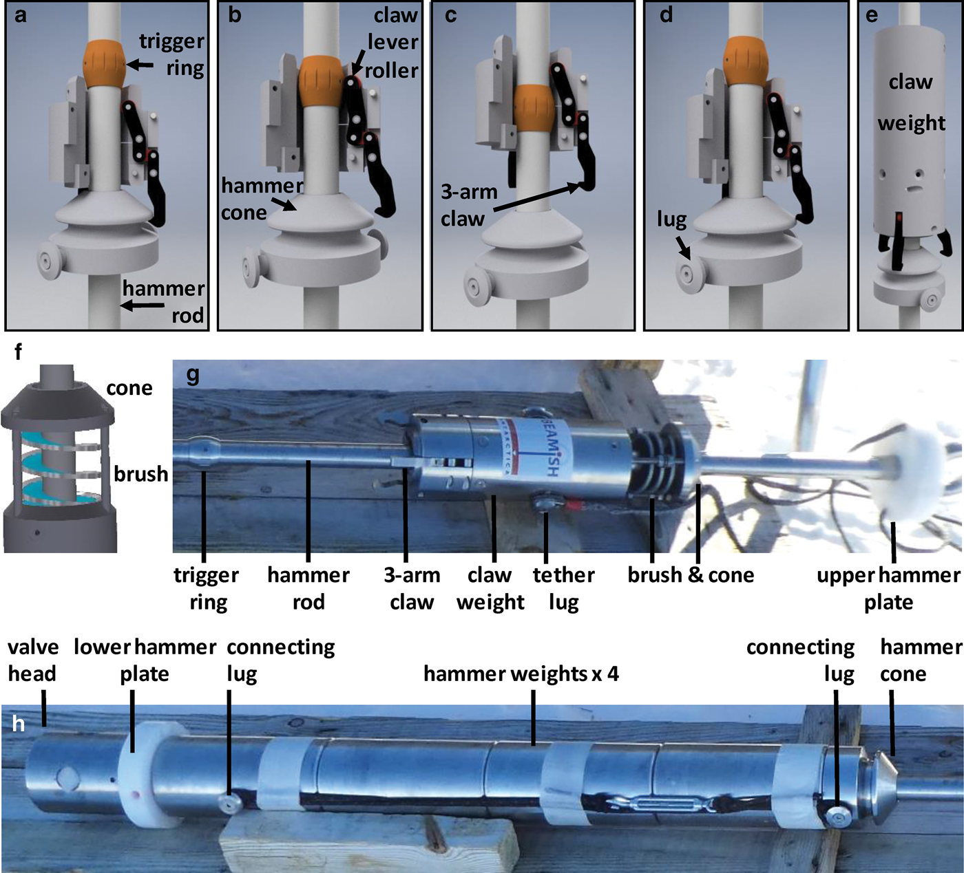
Fig. 2. Model components of the new hammer mechanism with cutaways of the 3-arm claw at different stages during the hammering cycle and photographs of the field assembly. (a) The spring-loaded 3-arm claw mechanism holds the hammer cone attached to the weight stack (see Fig. 2h) as it travels up the hammer rod until it reaches the trigger ring. (b) The claw lever roller at the top of the claw mechanism moves over the trigger ring, opening the claw, releasing the hammer cone and weight stack. (c) The release of the 20–40 kg hammer and the elastic stretch in the rope tether results in the claw recoiling up the hammer rod as the hammer free falls through the water to strike the hammer plate. (d) The claw is lowered down the hammer rod, past the trigger ring, until the three claw arms are forced open as they slide over and re-engage with the hammer cone. The hammer cycle can then repeat. (e) The complete claw assembly with the claw weight. (f) Model view of the cone and brush attachment mounted on the claw weight to mitigate against potential sediment rain down, in grounded ice access holes. (g) The upper section of the new percussion assembly including the 3-arm claw and (h) the lower assembly section including the four hammer weights prior to deployment in early 2019 on Rutford Ice Stream, Antarctica.
For operations on grounded ice where englacial sediment may be present, a brush and cone (Fig. 2f, g) fitted to the claw weight is used to prevent jamming of the 3-arm claw mechanism by sediments raining down from the hole sides during hammering operations. The cone deflects sediment away from the rod and the spiral brush sweeps any residual sediment from the hammer rod and trigger ring. This configuration operated reliably on Rutford Ice Stream where englacial sediments were present in the basal ice (Smith and others, Reference SmithThis volume).
Initial UK testing on Ullswater, recovered a 50 cm core from 50 m depth in 2016 and Antarctic field-testing in the austral summer of 2016/17 on northern Filchner Ice Shelf, recovered cores up to 152 cm long from 1240 m. These tests highlighted the need for small refinements. The claw mechanism spring sizes and strengths were adjusted, and a pin was added to prevent over-rotation of the claw roller arm and jamming of the mechanism. Weaker spiral brushes for easier transit past the trigger ring were also added.
The trigger ring positioning on the hammer rod is determined by the amount of tether recoil when the hammer is released. The claw unit should not hit the upper hammer plate with sufficient force as to lift the corer even a short distance and ideally should not hit the plate at all. At 2100 m for example, dropping a hammer with a weight in water of 29 kg, the recoil is ~80 cm.
5. Field operation
Understanding how tether stretch affects the relationship between load and line out-in distance at the surface during various stages of the percussion hammering process is essential for maximising sediment core recovery. Figure 3 shows schematic of the expected response in load as the tether and corer are lowered down the hole and during hammering operations. When deployed at the surface, the claw is held against the top hammer plate and the hammer weights are on the lower plate, therefore lowering the corer centre of gravity. During deployments beneath ice shelves, a lower centre of gravity will counteract ocean currents and help maintain corer verticality.

Fig. 3. Schematic plot of rope tether distance as a function of tether load at the surface. (a) Initial lowering of the corer and first hammer cycle. (b) Seven cycles of hammer releases and the resultant penetration into the sediment and initiation of corer withdrawal.
As the corer impacts into the sediment, all of the weight except for the claw is immediately removed from the rope tether. At the surface however, the load steadily decreases by ~80 kg as more tether is paid out and the elastic stretch associated with the corer and hammer weight is removed from the tether (Fig 3a). This initial decrease in load is about double that of the original corer as the hammer is initially deployed resting on the lower hammer plate. The load then remains constant as the claw travels down the length of the hammer rod. When the claw latches onto the hammer cone, the load reduces further as the elastic stretch associated with the claw is removed, until there is a minimum load on the tether and all the corer weight is on the cutter head (Fig 3a). The minimum registered load is from the section of the tether suspended in the air-filled part of the access hole. With the claw latched on the hammer cone, slowly winching in the tether takes in the elastic stretch and then lifts the hammer up the hammer rod. On reaching the trigger ring, activation of the claw releases the hammer, which free falls through the water and strikes the hammer plate. At the same time, the claw recoils up the hammer rod from the elastic stretch associated with the released hammer. This process is repeated and Figure 3b shows seven hammer cycles and incremental corer penetration into the sediment after each release of the hammer. Hammering stops either because the corer has penetrated 3 m and the barrel is full or no further penetration is possible as recorded by the line-out measurement or the reference marked on the tether at the initial impact. During corer pull out, winching in the tether will continue to stretch the rope until there is sufficient load to pull the corer from the sediment.
During sediment coring for the BEAMISH project on Rutford Ice Stream in early 2019, a short 10 cm core with gravelly sediment was recovered from the bed of one hole, confirming the presence of soft, water-saturated sediments at the ice stream bed (Smith and others, Reference SmithThis volume). Other coring attempts resulted in no penetration beyond the original depth of the hole, despite prolonged hammering. On return to the surface, the cutter had been damaged and bent inwards. This damage was consistent with repeated hammering against a hard basal or englacial boulder, or bedrock (Smith and others, Reference SmithThis volume). Despite the limited core recovery, the new hammer system operated without any problems, with load data providing clear evidence to the operators that the new percussive hammer system was repeatedly performing well, >2130 m below the surface in the water filled access holes.
Using data from the deep coring attempts on Rutford Ice Stream, the various stages of changing load over a period of 100 s are clearly displayed over a single hammer cycle in Figure 4. The approximate load initially registers just the weight of the rope tether hanging in the 235 m section of air-filled hole for 10 s, with the sediment corer supported by the sediment. Twenty seconds of winching takes in the rope tether stretch and increases the load until the full weight of the claw and hammer is taken by the tether (~57 kg). The claw and hammer are then raised up the hammer rod over a 10 s period. On reaching the trigger ring, there is a further 10 kg increase in load as the claw is forced open. The load then drops suddenly as the 40 kg hammer is released. At this point, the winch direction is reversed to recover the hammer. The load then plateaus for almost 40 s as the claw is lowered down the hammer rod. Over ~25 s the load decreases as the stretch associated with the claw is removed as it is forced to open by the hammer cone. Once the claw is latched onto the cone and all the weight (~17 kg) is resting on the corer hammer, only the weight of the tether in the air-filled section of hole remains.

Fig. 4. Field data from Rutford Ice Stream showing the approximate rope tether load over a 2-min period during the various stages of lifting, releasing and recovering the hammer during a single cycle at >2130 m depth.
6. Summary and future upgrades
A new hammer mechanism has been successfully retrofitted to the existing BAS-UWITEC sediment corer. Using a single 5 mm winched Dyneema® rope tether for both lowering and raising the corer, and operating the new percussive hammer mechanism, the corer successfully operated at depths >2100 m. The fully mechanical hammer auto-release and recovery mechanism provides operators with a clear, unambiguous load signal of its operation. This mechanism also increases the impact force of the hammer. By auto-releasing the hammer from the rope tether, the hammer can freefall through the water unimpeded by the hydrodynamic drag of the slightly buoyant rope tether that would slow its fall and reduce its impact force. To increase the impact force of the hammer further, longer hammer rods and a heavier hammer can deliver greater percussive force. The key attributes of this new mechanical percussion hammer mechanism are its unrestricted operational depth range, relatively simple operation, reduced learning curve and easy field maintenance, which extends the usefulness of the BAS-UWITEC coring system particularly in remote field environments where it is prohibitive to use larger drilling infrastructure.
In preparation for the planned clean accessing of Subglacial Lake CECs in West Antarctica (Makinson and others, Reference Makinson2021) and sampling of its sediments almost 3000 m below the ice-sheet surface, further modifications to the corer hammer section and tether are required. The modifications are necessary to conform to stringent cleanliness standards in preventing chemical or biological contamination of the subglacial lake environment. Various sterilisation techniques are available to achieve the required levels of cleanliness. Ideally, all corer and hammer section components should be easy to clean and be able to withstand steam or dry sterilising autoclave temperatures that range between 121 and 170 °C, high dosage gamma irradiation and sterilising chemicals such as hydrogen peroxide and ethanol. To achieve this, any plastic components are to be replaced with metal equivalents. To meet both the depth increase and cleanliness requirements, a new 3500 m long tether, 6.9 mm in diameter, with a Zylon® fibre core and polyurethane jacket will be used, which can withstand cleaning from high temperature (~90 °C) pressurised water jets, and high dosage ultraviolet light (>40 000 mJ cm−2). This tether will use a larger capacity winch. Leaving the core barrel dimensions unchanged but reducing the hammer plate diameter and replacing the claw weight and hammer lug attachment points, the maximum deployment diameter will be reduced to ~10 cm. This will allow the corer to operate in smaller diameter holes or give more downhole time with a reduced risk of entrapment as the water-filled borehole re-freezes. These further modifications will allow this simple mechanical corer to operate reliably in a wide range of environments and depths, including locations where stringent contamination controls are required.
Acknowledgements
This technical development was supported by the UK Natural Environment Research Council under AFI grant NE/G014159/1, Basal Conditions on Rutford Ice Stream: Bed Access, Monitoring, and Ice Sheet History (BEAMISH) and NERC grant NE/R016038/1, National Capability – Polar Expertise Supporting UK Research. The authors thank Alex Brisbourne for his helpful comments on an earlier version the paper. We also thank the useful feedback from our two anonymous reviewers and scientific editor Pavel Talalay.


 Open access