


1. Introduction
Various research and development projects have been conducted to realize humanoid robots that would be able to interact with humans in real-life situations [Reference Hoffman, Caron, Ferro, Sentis and Tsagarakis1]. Such robots can be useful not only for performing particular tasks in the place of humans but also for interacting naturally in a social environment. Concerning the social implementation of a humanoid robot called Pepper (SoftBank Robotics), several experimental outcomes have been reported. Pepper is intended as a conversational partner capable of performing various communication tasks, such as guiding people, talking with customers in public spaces, facilitating elderly care, and providing education for children [Reference Pandey and Gelin2]. In another project, natural human–robot communication with a limited number of failures has been realized by developing multiple table-top robots named CommU. These robots have been implemented in a real event [Reference Iio, Yoshikawa and Ishiguro3]. As the hardware technologies required for the development of humanoid robots and embedding them in a real environment have advanced considerably [Reference Nelson, Saunders and Playter4, Reference Gong, Hartley, Da, Hereid, Harib, Huang and Grizzle5], the expectations associated with the implementation of such robots in society are rapidly growing.
An android is a robot with a human-like appearance. It can interact with humans naturally owing to various features, for example, a face with multiple degrees of freedom (DoF) covered with human-like skin. For example, it can convey its internal state through changing facial expressions and demonstrate its intents with gestures. Humans use such expressions in their daily communication, and they can therefore intuitively understand these expressions. This should contribute to establishing a deeper relationship between humans and robots. Various androids have been introduced so far [Reference Ishiguro6, Reference Park, Lee, Hanson and Oh7], most of them representing adult persons. Generally, these robots have been assigned a specific role, such as a fashion model [Reference Miura, Nakaoka, Kajita, Kaneko, Kanehiro, Morisawa and Yokoi8], a conversation partner [Reference Milhorat, Lala, Inoue, Zhao, Ishida, Takanashi, Nakamura and Kawahara9], and a salesperson [Reference Watanabe, Ogawa and Ishiguro10], to embed them in daily life. One of the reasons for specifying a particular role for such robots and to use them only in a predefined situation is that with the current level of technological development, it is difficult to implement an android system that would be capable of responding adequately to all possible situations.
Most androids are not equipped with a moving mechanism. In the cases when hydraulic and pneumatic actuators are employed to realize these robots’ joint drive, they encounter difficulties in moving around, as a large compressor is required to drive these actuators. Several electric-drive androids with a moving mechanism have been introduced. A cybernetic human HRP-4C is a humanoid robot that has a human-like face and hands and can walk using legs [Reference Kaneko, Kanehiro, Morisawa, Miura, Nakaoka and Kajita11]. Due to the problem associated with the stability of bipedal walking, the environment where this robot can walk is limited. The other robot, EveR-4, is an android with a wheeled moving mechanism [Reference Ahn, Lee, Choi, Lee, Hur and Lee12]; however, the studies dedicated to this robot have mainly focused on analyzing its facial expressions, and the details concerning its ability to perform wheel movement have not been reported.
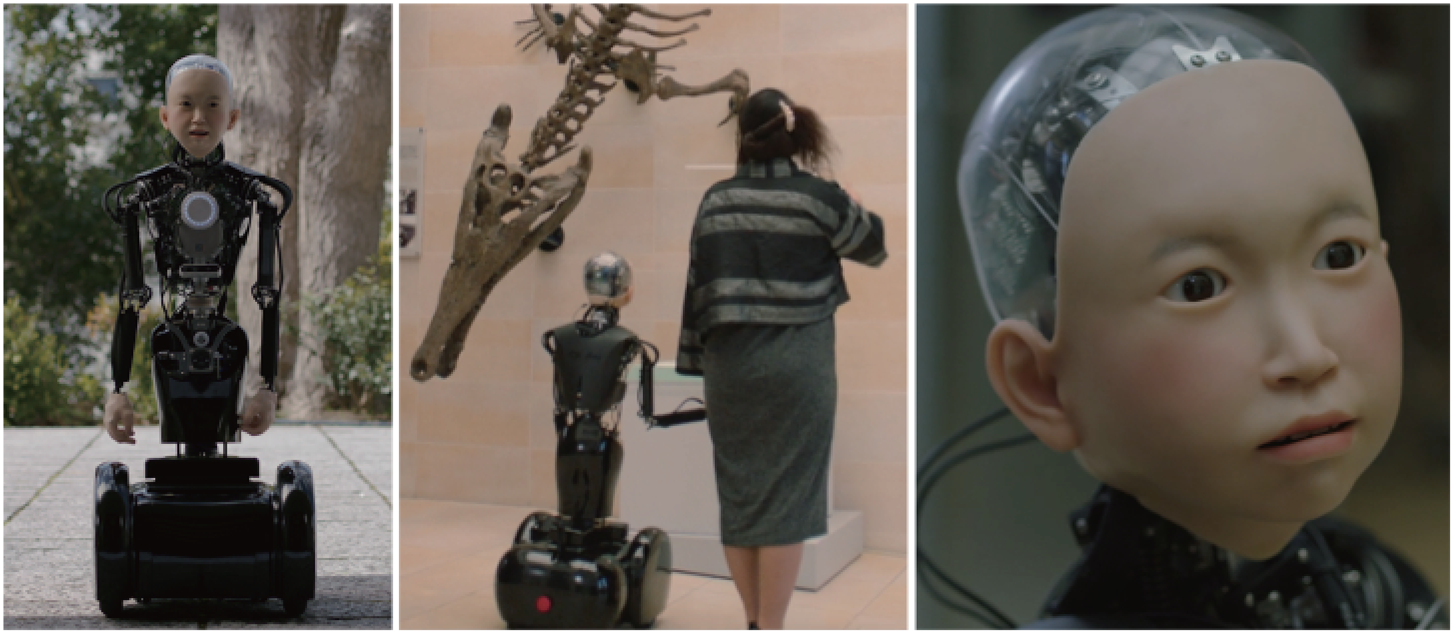
Figure 1. Introducing ibuki: a childlike android with mobility.
In the present study, we aim to develop an electrically driven childlike android with a mobility unit, named ibuki Footnote 1 (Fig. 1). Ishihara et al. have also introduced a childlike android called Affetto that has no mobility [Reference Ishihara and Asada13]. Their studies have mainly focused on simulating the human developmental process using an android. In its turn, the present research is aimed to investigate human–android interaction in a real environment. To do this, we implement a robot with a childlike appearance. Such androids can naturally exist in society without the need for a specific role as children do. Aiming to ensure the feasibility and stability of the proposed robot in a real environment, we equip it with a wheeled mobility unit. We note that ibuki can move not only in an indoor environment but also in slightly rough outdoor terrain. In implementing an android, it is essential to provide not only a human-like appearance but also human-like behavior. Even though it is a wheel-driven robot, the mobility unit enables ibuki to mimic movements corresponding to human gait-induced upper body motion and also to imitate walking. We consider that a childlike android would have advantages in terms of the following two aspects:
-
The safety of an android with mobility Wheel movement is deemed more stable than bipedal locomotion. Even if power is not supplied, a robot can keep standing still without falling. However, even in the case of wheeled robots, there is the possibility of unexpectedly contacting with a human while falling. A childlike robot can reduce this risk owing to its small size and weight. The psychological pressure on humans associated with an approaching object is also decreased.
-
The possibility of easy acceptance in human society At present, developing a humanoid robot that can handle any situation is one of the unsolved problems in robotics. As androids have a human-like appearance, people who encounter them may expect that their abilities are also on a human level. Generally, as expectations corresponding to children’s abilities are below than those of adults, a childlike android may behave naturally and respond appropriately even given the current technological level.
The contributions of this paper are as follows:
-
Development of a 46 DoFs electrically actuated childlike android with a wheeled mobility unit and its control system.
-
Development of a mobility unit that incorporates a vertical oscillation mechanism that drives the upper body up and down aiming to realize a human-like upper body motion during movement.
-
Confirmation through experiments that the trajectory of the apparent center of mass of the android while in motion is similar to that of human motion.
-
Implementation and testing of various motions on the android.
In the present paper, we introduce a childlike android with a mobility unit that can move in a real environment. The structure and the electric system of the proposed android are described. Then, we discuss in detail its abilities to regulate facial expressions, upper body motion and movements reproducing human gait-induced upper body motion. In addition, we consider walking hand in hand with the robot as an example of human–robot interaction. Finally, we consider the potential issues associated with the social implementation of this android and outline the future research direction of robotics, concerning the role of children in society.
2. A Childlike Android with Mobility
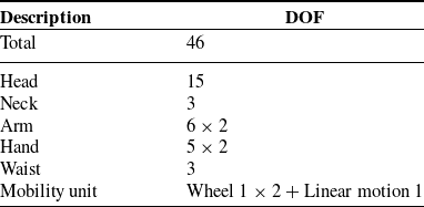
Figure 1 represents the proposed android ibuki that is 120 cm tall and is equipped with a mobility unit. It moves using a set of wheels for feasibility and safety reasons. The total weight of the robot including batteries is 38.6 kg. The weight of the upper body above the waist yaw joint is 9.1 kg. Tables I and II outline the basic specifications and the DoF of ibuki, respectively. The details of the android are described in subsection below.
Table I. Basic specifications of the mobile android ibuki
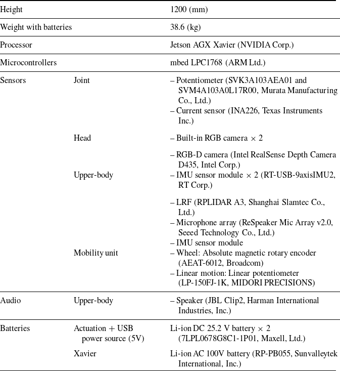
Table II. Degrees of Freedom of the Mobile Android ibuki
2.1. Human-like appearance
The dimensions of the robot’s body are specified according to the average parameters of a 10-year-old Japanese boy [14]. The head and both hands of the android are covered with the silicone skin that creates a human-like appearance. However, it is difficult to realize both flexibility and durability of the silicone skin simultaneously at the current level of technology. As the silicon skin with a sufficient level of durability becomes hard, the resistance to joint motion becomes high. Therefore, it may hinder the electric motor to move both joint structure and skin in respect of its maximum torque. Concerning the design of ibuki, we decided to cover only the required areas with skin, including the face and hands, so as not to lose the human-likeness of its appearance. Facial appearance is crucial to express emotions. Hands with flexible skin can be utilized to touch humans, as when shaking hands or during other such interactions. In the design of other body areas, the mechanical parts are intentionally exposed to reduce the spookiness of the robot’s appearance.
2.2. Mechanical design
Figure 2 represents the mechanical structure of ibuki. It has a total of 46 DoF, including two active wheels (See Table II). All actuators are DC-geared motors that are regulated by microcontrollers. Motor driver modules equipped with current sensors enable ibuki to control its joint torque. Table III provides the principal joint specifications.Footnote 2
Table III. Principal Joint Specifications
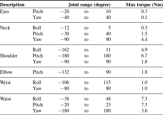
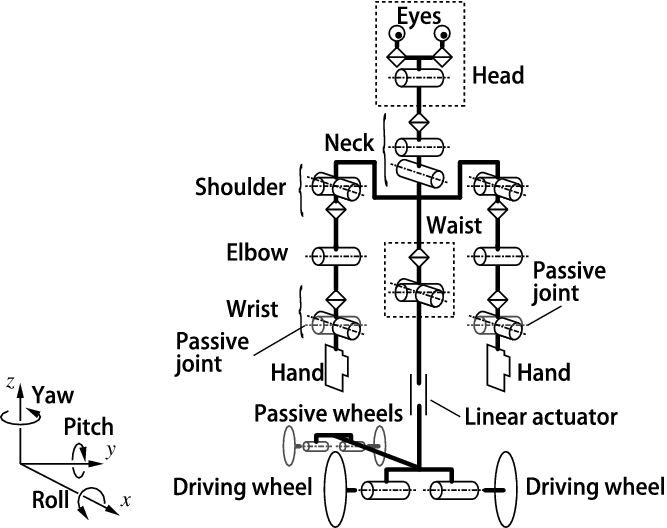
Figure 2. The mechanical structure of ibuki. The wrist roll axes of both arms are specified as passive joints. Mechanical springs are attached to each joint.
2.2.1. Mobility unit
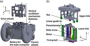
Figure 3(a) shows a three-dimensional computer-aided design (3D CAD) image of the mobility unit composed of a wheel unit and a vertical oscillation mechanism (VOM). The wheel unit comprises two driving wheels at the front and two omnidirectional wheels as passive ones at the rear. The rotation angle of each driving wheel is measured by a magnetic rotary encoder (AEAT-6012, Broadcom). Figure 3(b) represents a 3D CAD image of VOM. It consists of a linear actuator using a motor-driven slide screw. The displacement is measured by means of a linear potentiometer (LP-150FJ-1K, Midori Precisions). Table IV represents the principal specifications of the mobility unit.
Table IV. Principal specifications of the mobility unit
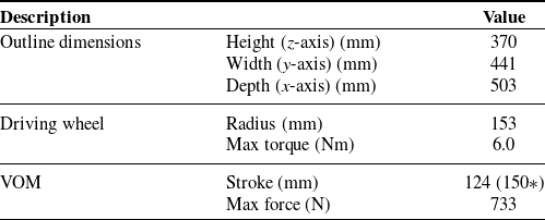
*Stroke (mm) without stopper.
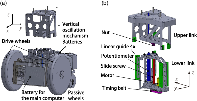
Figure 3. Three-dimensional computer-aided design image of the mobility unit: (a) the whole view of the mobility unit and (b) the vertical oscillation mechanism.
2.2.2. Head and neck
The head (Fig. 4) and the neck have 15 and 3 DOF, respectively. The eyeball movements are regulated by motors via a belt or links. The yaw movements of each eyeball are performed independently. The pitch movements are in conjunction. Concerning upper and lower eyelids and jaw, movements are realized by regulating motor-driven plastic shells on which the silicon skin is glued. The upper and lower lip motions are performed by pushing the skin using sticks. To enable the other skin movements, fishing lines pulled by the motor are glued under the skin. Three 5-axes motor driver modules (headc, headl, and headr) corresponding to the 15 head motors are installed inside the head to reduce the number of cables passing through the neck.
Figure 4. Degrees of freedom of the robot’s head. Here, $c_0, \dots, c_5$
are regulated by the headc motor driver module;
$c_0, \dots, c_5$
are regulated by the headc motor driver module; $l_0, \dots, l_5$
are regulated by the headl motor driver module;
$l_0, \dots, l_5$
are regulated by the headl motor driver module; $r_0, \dots, r_5$
are regulated by the headr motor driver module.
$r_0, \dots, r_5$
are regulated by the headr motor driver module.
2.2.3. Arm and hand
Figure 5 shows the 3D CAD image of the robot’s upper body. Figure 5(a), (b), (c), (d), and (e) represents the top view, front view, forearm, shoulder, and wrist joint, respectively. Each arm has six active joints and one passive one (wrist roll) with two mechanical springs (Fig. 5(e)). The arm is connected to the body under 20 degrees to imitate the natural shoulder angle which result from shoulder blades. To enable a natural arm posture, including the hand, the physiological extraversion of the elbow is realized by connecting the forearm to the upper one under 15 degrees. The upper arm and forearm are composed of carbon pipes to save weight. Two motors are embedded in each pipe (Fig. 5(a)).
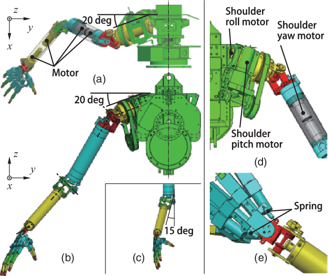
Figure 5. Three-dimensional computer-aided design image of the ibuki’s upper body: (a) top view; (b) front view; (c) forearm; (d) shoulder; and (e) wrist joint.
Figure 6 represents the structure of a hand that has five DoFs. The length of the hand is 140 mm, and its total weight is 195 g, including five DC-geared motors. The weight of the artificial skin is 95 g. The hand of ibuki is one of the smallest and the most lightweight prosthetic robotic hands which includes actuators [Reference Tian, Magnenat Thalmann, Thalmann and Zheng15]. Each finger bone is implemented using a 3D printer and can be moved using a thread pulled by a motor built into the palm. The thumb carpometacarpal (CMC) joint is not implemented. However, as the thumb is fixed to form a hand shape corresponding to a holding action, ibuki can move its hands in order to hold hands or grasp objects.
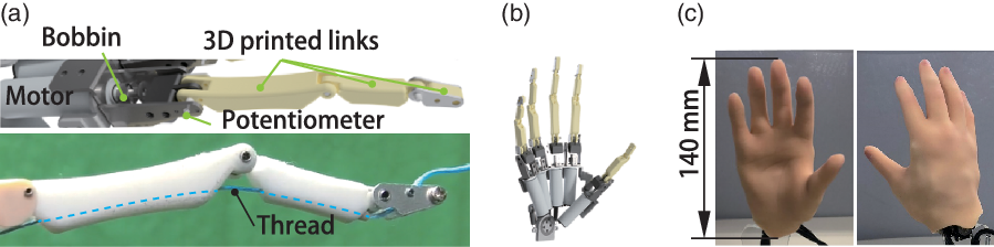
Figure 6. The structure of the robot’s hand: (a) the structure of the finger; (b) a three-dimensional computer-aided design image; and (c) the photographs of the hand.
2.2.4. Waist joints
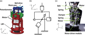
Figure 7(a) represents a 3D CAD image of the waist; (b) represents the schematic image of the structure; and (c) shows the photograph of the joint. We specify that the robot’s waist has three DOFs. A gimbal structure is employed for roll and pitch joints. Mechanical springs and dampers are combined within each joint to support joint motion. To prevent the structure from becoming longer in the z-axis, the yaw motion is transmitted by a belt from a motor whose rotational axis is placed along the x-axis.

Figure 7. Waist joints: (a) three-dimensional computer-aided design of the waist joint mechanism; (b) a schematic image of the waist joint; and (c) a photograph of the waist joint.
2.3. Electrical system
Figure 8 represents the electrical system embedded into ibuki. The utilized on-board main computer, Jetson AGX Xavier, is mounted on the mobility unit. Since ibuki was developed to move around in a real environment, it is necessary to assume that the network environment may be unstable during the android working. Thus, this computer is used for applications where relying on the computational power of the cloud or server would delay the response time. The other additional calculations are performed on an external computer. Each motor driver module is connected via Ethernet, and the sensors are connected via USB.

Figure 8. Electrical system of ibuki.
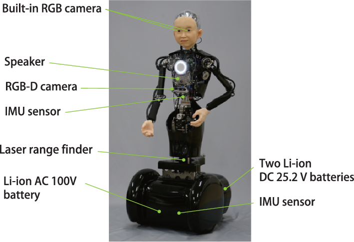
Figure 9. Sensors and other devices embedded into ibuki.
Figure 9 outlines the arrangement of sensors and other devices within ibuki. The laser range finder (LRF) is used to perform measurement of its surroundings. The RGB-D camera is utilized to detect a person or an object in front of the android. A small camera mounted inside each eye is employed to detect a face or an object and execute the gaze control. Here, we explain the details using the example of person tracking. First, we use LRF to detect the direction of the person’s presence relative to ibuki. Next, a camera attached to the body captures the entire body of the person. At this time, we use OpenPose [Reference Cao, Hidalgo, Simon, Wei and Sheikh16] to obtain the body structure and identify the position of the head. Finally, the face is detected using the eye cameras with OpenCV [17] face tracking, and the gaze is controlled. The control was implemented using image-based visual servoing. The eyeballs’ angles were controlled so that the person’s face was in the center of the image acquired by the eye camera. Then, the neck angle was controlled so that the gaze and the face directions were the same. Since the eye cameras do not have a large viewing angle, we give different roles on the body camera and eye cameras. In the case of object detection, the body-mounted camera is used for global recognition and then the eye cameras are used for tracking.
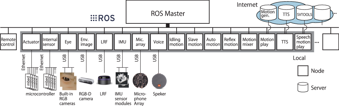
Figure 10. The ROS-based software package for androids called “SILVA”.
2.4. Control framework
A ROS-based software package SILVA which we developed is implemented to control ibuki [Reference Yu, Nishimura, Yagi, Ise, Wang, Nakata, Nakamura and Ishiguro18]. Figure 10 provides an overview of SILVA. We integrate a large-scale android system into a sorted term by adopting multiple functions in the form of ROS nodes. This implementation allows for easy sharing of information within a development community as well as simple updating of the software package by adding simple additional application nodes or node packages. In this framework, the communication has 10–100 ms delays due to the amount of communication data and the transmission delay corresponding to the on-body Ethernet. Such response speed is acceptable for executing the interaction tasks of an android. For interaction purposes, it is not necessary to provide the same accuracy as is required for an industrial robot. The description of the key nodes is provided below.
-
Idling motion node generates idling movements, such as blinking, eye movements, and unintentional upper body fluctuations.
-
Slave motion node receives and transmits the inputs from an operator. Auto motion node receives and transmits the information from the external environment obtained by sensors.
-
Reflex motion node realizes muscle reflex like motion. It generates the position or angle of each actuator using the feedback from internal sensors and the pre-programmed position or angle constraints of each joint as inputs.
-
Motion mixer node incorporates the inputs from the four nodes listed above by multiplying their weights and providing outputs to each actuator.
-
TTS node communicates with a text-to-speech server via the Internet. The inputs are Japanese text strings, while the outputs include converted audio files, which serve as the speech voice for the android.
-
Speech motion play node communicates with the SVTOOLS [Reference Ishi, Liu, Ishiguro and Hagita19] server, which can generate the lip, neck, and waist joint movements based on speech recognition.
-
Motion play node publishes the relative actuator positions with action time by reading the motion play files (.csv).
-
Remote control node communicates with another command computer and allows the operator to control android states. The inputs can be the relative actuator positions, joystick messages, a text string, etc. Figure 11 shows a control panel for the remote control.
3. Experiments
To test the proposed android, we conducted several experiments, considering various behavior patterns corresponding to facial expressions, whole body motion, the movement underlying gait-induced upper body motion, and human–robot interaction.
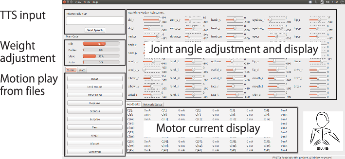
Figure 11. Control panel for the remote control.

Figure 12. Facial expressions.
3.1. Facial expressions
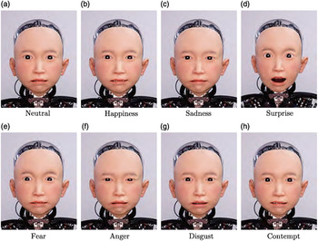
Figure 12(a)–(h) represents the eight different facial expressions of ibuki including the neutral one, specified according to the research reported by Ekman et al. [Reference Friesen and Ekman20, Reference Matsumoto and Ekman21]. Table V provides the correspondence between the action units related to each emotion and the actuator on the robot’s head. The number of actuators is much smaller compared with that of human facial muscles. Therefore, we had to carefully select the corresponding actuators and ignore the facial movements for which there was no actuator available. The lower part of Table V represents the list of action units in the facial action coding system.
3.2. Body motion
Figure 13 provides the various hand motions, including hand signs, grasping, and pinching. The laser pointer in the second photograph from the right weighs 61 g, and the metal bevel gear in the rightmost photograph weighs 16.8 g.
Table V. Definition of the relationship between action units and the actuators of the face of ibuki in different emotions
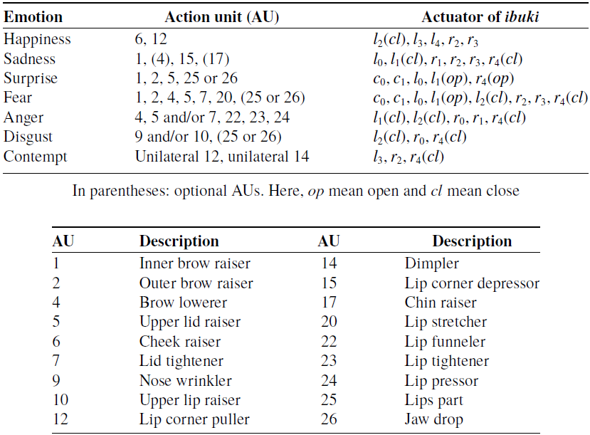
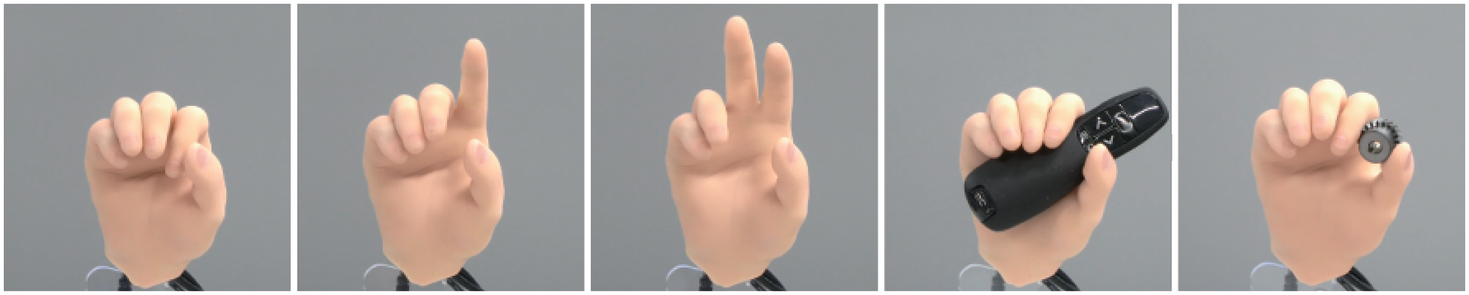
Figure 13. Examples of the hand signs, grasping, and pinching.
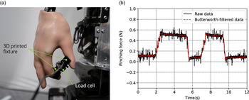
Pinching force was measured for evaluation. We made a measurement device using a load cell (LCM201-100N, Omega Engineering Inc.) and 3D printed fixtures. Figure 14(a) shows the photograph of the experimental setup. The control was designed to perform the closing and opening motions of the thumb and forefinger twice. Figure 14(b) shows the measurements of the pinching force. The maximum pinching force is 0.5 N. The reason why the pinching force was not as large as it should be is likely the lack of a CMC joint, which prevented the thumb and the index finger from completely facing each other, and thus some force was lost.
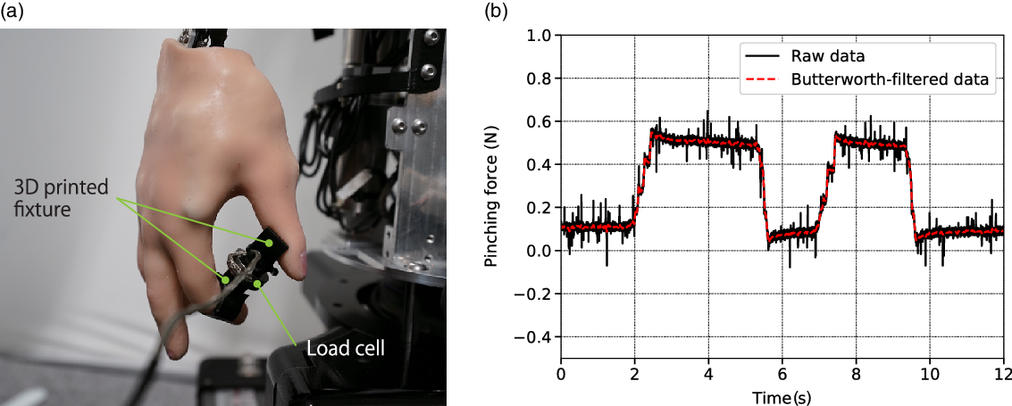
Figure 14. Pinching force: (a) the photograph of the experimental setup; (b) the measurement result of the pinching force.
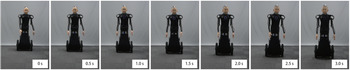
Figure 15 shows an example of the robot’s whole body motion that expresses the movement of bending down and touching an object. ibuki does not have any rotational joints in its lower body, such as knee and ankle joints. However, ibuki can perform particular actions, such as standing on its tiptoes and squatting by changing its height using the VOM embedded into the mobility unit.
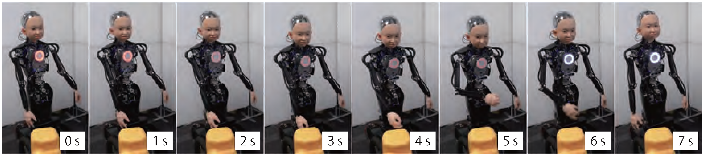
Figure 15. Time series photographs of the whole body motion of the android. Here, ibuki bends over and touches an object by a hand.
3.3. Gait-induced upper body motion using the mobility unit
During the human walking process, all the body parts are coordinated and move simultaneously. The human center of mass (CoM) is located near the center of pelvis. Its position may be affected both by upper and lower limbs. In this experiment, we modeled the trajectory of the human CoM during walking and controlled the position of the robot’s apparent CoM (aCoM) to achieve human-like motion.
We assumed that the trajectory of the human CoM on the sagittal plane during walking could be approximated by a cosine wave [Reference Zijlstra and Hof22]. When the gait cycle starts from the double-support phase, the position of the VOM d(t) can be expressed as follows:
 \begin{equation}d(t)=-d_A \cos (4\pi p t)+d_0\end{equation}
where $d_A$
and
$d_A$
and $d_0$
are the amplitude and baseline of the VOM position, respectively. Here, p is the walking pitch of walking; t is time. In a single gait cycle, aCOM oscillates once per step. Therefore, the frequency of VOM is twice as large as that of the gait. The arm motion (joint angle
$d_0$
are the amplitude and baseline of the VOM position, respectively. Here, p is the walking pitch of walking; t is time. In a single gait cycle, aCOM oscillates once per step. Therefore, the frequency of VOM is twice as large as that of the gait. The arm motion (joint angle $\theta(t)$
) is defined as follows:
$\theta(t)$
) is defined as follows:
 \begin{equation} \theta(t)=\theta_A\sin(2\pi pt + \phi) + \theta_0\end{equation}
where $\theta_A$
and
$\theta_A$
and $\theta_0$
are the amplitude and baseline; respectively,
$\theta_0$
are the amplitude and baseline; respectively, $\phi$
is the phase difference.
$\phi$
is the phase difference.
Figure 16 represents the movements of ibuki. We note that the specifications of VOM and each joint follow Eqs. (1) and (2). In this experiment, we utilized eccentric wheels for realizing motion in a coronal plane, that is, lateral swinging. If normal wheels were employed, the waist roll joint could be utilized to realize balancing motion during walking.
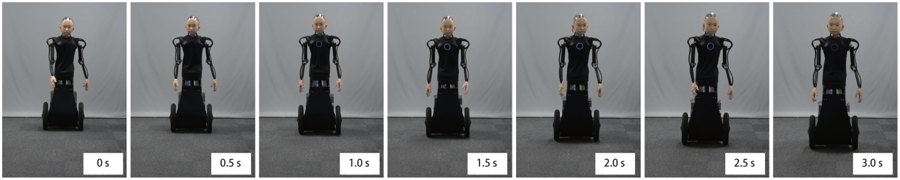
Figure 16. Time series photographs of the gait-induced upper body motion during movement.
We measured the trajectory of the points around the waist on the coronal plane during movement. Figure 17(a) shows the time series photographs during the experiment. A motion capture system (OptiTrack V120: Trio, NaturalPoint, Inc.) was used for the measurement. Figure 17(b) shows the arrangement of two reflection markers (A and B). ibuki moved toward the motion capture camera. The trajectory of the movement on the horizontal plane is shown in Fig. 17(c). The trajectory of each marker was examined in the interval beginning with a circle and ending with a diamond. Figure 17(d) and (e) shows the trajectories of the markers A and B projected on the coronal plane, respectively. These trajectories are as seen from the diamond side. The trajectory of marker B is longer horizontally than that of marker A because of the passive swing of the roll axis of the hips during movement.
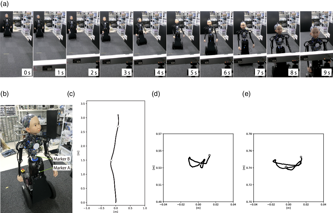
Figure 17. The measurement of the gait-induced upper body motion: (a) time series photographs of the motion; (b) arrangement of the reflection markers; (c) trajectory of the ibuki’s movement on the horizontal plane; (d) trajectory of the marker A; and (e) trajectory of the marker B.
3.4. Human–Robot interaction
As an example of a human–robot interaction function, we considered motion while walking hand in hand with the person. This function corresponds to the potential application of guiding a person. By holding ibuki’s hand, the user could detect and follow the direction in which ibuki moved. An internal sensor (a potentiometer embedded at the shoulder) and LRF were implemented. The potentiometer was utilized to detect changes in the shoulder roll joint angle to detect the user pulling ibuki’s arm. LRF was employed to measure the distance between the user and ibuki, as well as the direction of the user’s position. In this experimental implementation, ibuki was controlled to follow the user.
Figure 18 outlines the time series of the images representing the process of walking with ibuki. If the user pulls an arm, ibuki changes the direction of movement in order to follow him or her closely.
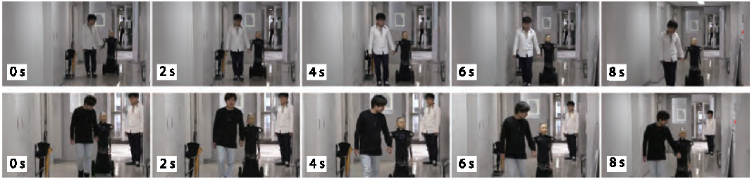
Figure 18. Time series photographs of the android that autonomously moves hand in hand with a human.
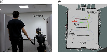
We also created a motion in which ibuki leads a person by holding his or her hand. We made a map of the environment using the LRF on the ibuki and then defined trajectories for the movement of the ibuki. It is moved by using SLAM. In this experiment, we assumed that ibuki always holds hands with the person, so we did not consider the person’s location while controlling ibuki. Figure 19(a) shows a photograph of the subject during the experiment. Figure 19(b) shows the map of the environment and the planned path.
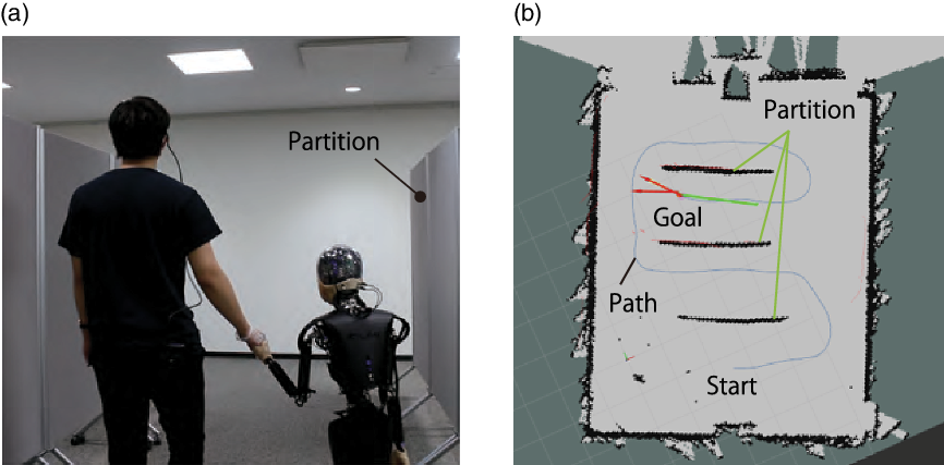
Figure 19. Guiding by ibuki: (a) Guiding hand in hand with a human; (b) planned path of ibuki.
4. Discussion
Whole body motion of ibuki was realized by means of the integrated 46 motors and sensor groups. It was capable of reproducing the merged motion comprising these different types of movements by using the developed ROS-based control framework.
Eight different facial expressions were created. Generally, the silicon skin was harder than the human one. Even if we applied large deformations to the skin with the aim of realizing considerable changes in the facial expression of the robot, the resulting expression could seem unnatural in particular cases due to differences in material properties. To pull the skin with a large force, a motor with high reduction gear would be required so the response would be impaired. We consider that thin skin could be pulled more effectively with a small force; however, its durability would be low. Therefore, the precise facial expression corresponding to happiness was difficult to realize as large deformations of the cheeks were not achievable. In this experiment, the angle of each neck joint was constant; however, humans change their whole body posture according to emotional state. Therefore, considering emotional expressions corresponding to the whole body would be effective for establishing natural communication [Reference Zecca, Mizoguchi, Endo, Iida, Kawabata, Endo, Itoh and Takanishi23].
In the present study, the whole body motion of the robot was realized by integrating the movements of arms, neck, waist, and vertical oscillation. As ibuki moved with wheels, it was unlikely to fall due to the loss of balance control. Accordingly, we could aim to specify its movements with a focus on human-like appearance and behavior. Concerning moving outdoors, natural postural control relying on ground tilt is planned for future research. In addition, updating the mobility unit to enable the android to traverse larger steps and stairs is also a challenge [Reference Tao, Xu and Liu24].
In Fig. 17(d) and (e), the trajectories of the points around the waist on the coronal plane during movements are roughly a figure of eight, which is similar to the trajectory of a human CoM motion [Reference Cappozzo25, Reference Tesio, Rota, Chessa and Perucca26]. Utilizing VOM and eccentric wheels, as well as implementing human gait-induced upper body motion, enabled ibuki to move like a human, even when moving on wheels. The human gait is not always constant, as it can be affected by the speed of movement, the state of the ground surface, and emotional state. We have implemented emotional gait-induced upper body movements for ibuki [Reference Yagi, Ise, Yu, Nakata, Nakamura and Ishiguro27]. However, incorporating the moving speed and the environmental aspects remain as open questions. It is known that people’s movement while walking influences one another [Reference van Ulzen, Lamoth, Daffertshofer, Semin and Beek28]. For example, when two people are walking, the mutual first impressions change the degree of entrainment of each individual’s gait [Reference Cheng and Kato29]. Using this mobile robot platform, in the future, we will investigate how the motion of CoM, that is, an additional degree of freedom, influences human–robot interaction [Reference Yagi, Nakata, Nakamura and Ishiguro30].
The potential applications of ibuki include guiding, providing information, life support, and human learning support. For example, when older people are guided by ibuki, they can not only hold ibuki’s hand for safe guidance but they might also feel they are talking to a child and interact with it in a fun way. In fact, for example, we have seen many times visitors to the laboratory act as if ibuki were a child, such as when they matched their eye level to ibuki’s.
To widely adopt robots as symbiotic partners in daily life, people need to rely on a framework that allows not only for the performance of predefined movements but also allows for the learning of suitable behavior patterns during activities in a real environment. However, similarly to the difficulties encountered in living alone in society, in an actual environment, a robot may encounter many difficult situations that are impossible for it to overcome by itself. We focus on children who grow up in society while learning appropriate social behavior patterns with the help from others or by interacting with them. Walking hand in hand with a person is one of the examples of such assistance. We believe that having a childlike appearance and movements would be beneficial for robots to coexistence with humans in society owing to the following three reasons:
-
Co-parenting Humans raise children and care about them instinctively in cooperation with others. Regardless of age or gender, we feel that children are cute and need protection unconditionally [Reference Kringelbach, Stark, Alexander, Bornstein and Stein31]. With the current level of HRI technologies, interacting with robots in an active and long-term manner is difficult. An android that has childlike appearance and behavior has the potential to induce more active involvement from humans.
-
Immaturity Children cannot adequately act without encountering difficulties. Similarly, at present, even robots based on the state-of-the-art technologies are not mature enough to operate autonomously in society. Generally, when people interact with androids, they expect them to have comparable intelligence to humans. Having a childlike appearance and behavior would enable androids to lower such expectations of their intelligence and might also make people feel protective toward them [Reference Alley32]. If the appearance or behavior of a robot is immature, people might adapt to the robot and assist it [Reference Nishiwaki, Furukawa, Yoshikawa, Karatas and Okada33]. For example, humans often make exaggerated gestures or talk slowly if the other party is a child. These behavior patterns would mitigate the insufficiency of the current image and voice recognition technologies. We consider that childlike androids have the potential ability to establish understandable behavior patterns by learning from humans naturally.
-
Existence To maintain fluent and efficient communication, sharing stories, or experiences are considered beneficial [Reference Matsumura, Shiomi and Hagita34]. Humans have particular knowledge about what is to be children, as they also used to be children in the past. We can interact with children relatively easily even if we meet them for the first time, as we have general expectations about their behavior in advance. This is not the case when using ordinary robots. Therefore, childlike androids can initiate interactions with humans as if they already have defined relationships with people and society.
As the next step, we plan to conduct the research and development of an advanced childlike android ibuki that can learn the social behavior patterns required to perform activities in a real environment. We plan that ibuki will keep inducing human actions, as well as receiving the required assistance and care that is usually reserved for children, owing to its childlike appearance and behavior. We refer to this new robotic research as “social upbringing robotics.” We plan to implement and evaluate a robotic system that is capable of establishing a symbiotic relationship with humans through exploiting its childlikeness, learn behavior patterns from interactions with people, and use the knowledge obtained in appropriate social situations.
5. Conclusions
In this paper, we introduced an electrically actuated childlike android with wheeled mobility called ibuki. We described the mechanical system of its upper body, as well as the mobility unit and the underlying electrical system. To prove its applicability, we implemented and tested its facial expressions and body motions, as well as gait-induced upper body motion in order to demonstrate how the proposed android acts and appears during movement. Moreover, we realized and tested several functions for human–robot interactions. The performance and limitations of the proposed android were discussed. Finally, we considered the benefits and the potential of using a childlike appearance and behavior to realize a robot that is capable of learning social behavior patterns by inducing and analyzing human actions in a real environment.
Code and Other Materials
Acknowledgements
This work was supported by JST ERATO Grant Number JPMJER1401 and Grant-in-Aid for JSPS Fellows Grant Number JP19J20127.


 Open access