Introduction
The prediction of large icefalls from hanging glaciers can reduce loss of life and damage to settlements. A common predictive method is based on the regular acceleration observed on large ice masses prior to collapse. Thetime of breaking-off was forecast quite accurately by Reference FlotronFlotron (1977) and Reference RöthlisbergerRöthlisberger (1977) on a hanging glacier located on the east face of the Weisshorn, Valais, Switzerland. They extrapolated the velocity–time function measured on the unstable glacier during the months preceding the icefall. The extrapolation was performed according to the equation
which describes the increasing velocity v(t) of the unstable ice mass before breaking-off v0, a, m and tf are parameters. tf corresponds to the failure time. Describing a stepwise crack extension coupled to a viscous flow, Reference IkenIken (1977) showed that the acceleration of an unstable ice mass can be expressed by Equation (1). This equation is widespread. It describes the fracture of materials such as rock, soil and high-performance metal alloys (Reference VarnesVarnes, 1983) and allows high-magnitude earthquakes to be predicted with an uncertainty of 2 years (Reference Bufe and VarnesBufe and Varnes, 1993; Reference Bowman, Ouillon, Sammis, Sornette and SornetteBowman and others, 1998). To improve this approach for hanging glaciers, a numerical model is developed to describe breaking-off processes.
The influence of crevasses on glacier motion and crevasse pattern formation are severe problems for glacier flow modeling. The material discontinuities due to crevasses require a complex, time-dependent model geometry. To avoid the description and the continuous adaptation of the glacier geometry, the ice and the crevasses are treated in a continuum approach as a unique domain composed of regions with distinct material properties. The difficulty of interface location can be solved appropriately by a level-set method (Reference SethianSethian, 1999; Reference Osher and FedkiwOsher and Fedkiw, 2001). A level-set function φ (x , t) localizes the material position, and is defined by φ (x , t) = 1 inside the material and by φ (x , t) = –1 outside it. The interface is defined by φ (x , t) = 0. The variation of φ (x , t) in time and space at the interface is described by the transport equation
where ![]() is the velocity field at the interface.
is the velocity field at the interface.
The description of crevasse opening based on fracture mechanics implies a non-trivial criterion (C*-Integral) for crack propagation in a viscoelastic medium (Reference A.Saxena, 1998) or assumes a linear elastic description of the fracture in ice (Reference Van der VeenVan der Veen, 1998; Reference RistRist and others, 1999, Reference Rist, Sammonds, Oerter and Doake2002). Furthermore, the subcritical crack growth process (Reference Atkinson, Meredith and AtkinsonAtkinson and Meredith, 1987), which is crucial for describing the dynamics of crack opening, has yet to be studied for ice. If multiple interacting crevasses or macro-fractured ice domains are considered, further difficulties emerge from fracture mechanics. To describe the progressive fracturing of a hanging glacier, continuum damage mechanics is an efficient alternative to fracture mechanics. An equivalence principle (Reference Skrzypek and GanczarskiSkrzypek and Ganczarski, 1999) is used, which “allows to describe the mechanical behavior of the damaged material using the constitutive equation formalism of the undamaged material” (Reference Weiss, Tuhkuri and RiskaWeiss, 1999). It results in a modified rheology of the undamaged material which accounts for material deterioration due to damage. A variable, D(x, t), is introduced to describe the progressive deterioration. Isotropic damage is represented by a scalar variable; orthotropic damage by a second-order tensor; and total anisotropic damage by a fourth-order tensor. In case of isotropic damage, the variable D is increasing from D = 0 (no damage) to D = 1 (full damage). Isotropic damage evolution in time and space is described as
where f = f(ἑ, D, T, p) is the dynamic function of damage depending on the strain rate ἑ, the damage D, the temperature T and the density p. It was evaluated for ice thermodynamically (Reference SjolindSjolind, 1987; Reference Derradji-Aouat and EvginDerradji-Aouat and Evgin, 2001), in a microscopic (Reference Choi, Karr, Sinha, Sodhi and ChungChoi and Karr, 1989; Reference Santaoja, Sinha, Sodhi and ChungSantaoja, 1989) and in a mesoscopic approach (Reference Pulkkinen, Sinha, Sodhi and ChungPulkkinen, 1989; Reference Mahrenholtz, Wu, Murthy, Sackingerand and WadhamsMahrenholtz and Wu, 1992), or with a correspondence to fracture mechanics (Reference SchaperySchapery, 1984,Reference Schapery, Jones, Mckenna, Tillotson and Jordaan1991). Fracturing occurs in a material if the damage D passes a critical Dc (Reference LemaitreLemaitre, 1992). The ice is then considered to be broken and D is instantly set equal to 1. This can be associated with the transition of subcritical to critical crack growth.
Model
To compute in a continuum approach the motion of a glacier with crevasses, the behaviors of ice, broken ice (where damage has reached the value Dc) and air have to be defined.
Ice rheology
The loss of area in a material section due to microcracks is represented by the damage variable D. To preserve a dimensionless variable, the loss of area is scaled by the considered area section. To guarantee the validity of a continuum approach, the section area must be chosen large compared to the size of individual microcracks. A representative volume element is defined at the mesoscale. It delimits the resolution and the validity of the model. For polycrystalline ice, this volume corresponds to 103–106 times the volume of an ice grain.
To simplify the model, it is postulated that damage does not affect the ice density. It is also postulated that damage in ice is sufficiently described by one single scalar variable (isotropic damage). The behavior of undamaged ice is described by Glen’s flow law. The total energy equivalence principle (Reference Chow and LuChow and Lu, 1992) couples the damage and Glen’s flow law to describe the rheology of damaged ice. The modified Glen’s flow law is
where ![]() is the deviatoric part of the effective stress tensor replacing the deviatoric part of the stress tensor (σ)' in Glen’s flow law,
is the deviatoric part of the effective stress tensor replacing the deviatoric part of the stress tensor (σ)' in Glen’s flow law, ![]() the effective strain-rate tensor replacing the strain-rate tensor ἑ, and
the effective strain-rate tensor replacing the strain-rate tensor ἑ, and ![]() the second invariant of the effective strain-rate tensor. The effective stress and strain rate for isotropic damage are
the second invariant of the effective strain-rate tensor. The effective stress and strain rate for isotropic damage are
Equation (4) can be expressed in classical terms of stress, pressure and strain rate:
with the ice viscosity
To avoid an infinite viscosity, П e cannot be smaller than a value γ. The use of the total energy equivalence principle leads to the same equation of ice rheology as the use of a dissipational potential for creep-damaged material described by Reference Wu, Mahrenholtz, Nixon, Sodhi, Sinha and AyorindeWu and Mahrenholtz (1993). By using the total energy equivalence principle, the physical definition of damage is, however, lost (Reference Lemaitre, Desmorat and SauzayLemaitre and others, 2000). The damage variable D then no longer describes the loss of area due to cracks. But the variable D introduced in the effective stress and strain rate (Equation (5)) is defined by satisfying the total energy equivalence principle.
Here a generalized Kachanow dynamic function of damage by Reference Wu, Mahrenholtz, Nixon, Sodhi, Sinha and AyorindeWu and Mahrenholtz (1993) (for damage satisfying the total energy equivalence principle) was adopted and extended. For isotropic damage this function is

with
Here X(σ) is the characteristic stress inducing damage accumulation, a I the maximum principal stress and Пy the second invariant of the deviatoric part of a. For our model calculations, the values used for the material parameters B, α, Γ, a1 and a2 were taken from Reference Mahrenholtz, Wu, Murthy, Sackingerand and WadhamsMahrenholtz and Wu (1992) and Reference Wu, Mahrenholtz, Nixon, Sodhi, Sinha and AyorindeWu and Mahrenholtz (1993). They analyzed the creep damage behavior of polycrystalline ice under tension and compression by using cylindrical specimens (120 mm length and 43 mm diameter) with grain-size of approximately 1 mm. Thus, their experiments are assumed to describe a mesoscopic damage process. Only the parameter B is considered to be temperature-dependent. It is supposed to vary with temperature according to the Arrhenius relation with an activation energy of 67 kJ mol–1 (Reference Derradji-Aouat and EvginDerradji-Aouat and Evgin, 2001).
It is proposed to add a crack-healing effect depending on hydrostatic pressure. Considering that X(σ) enhances the growth of microcracks and the pressure p counteracts their increase, a new characteristic stress ψ is introduced in accordance with Reference Derradji-Aouat and EvginDerradji-Aouat and Evgin (2001). ψ is expressed such that ψ = σ for uniaxial tension,
Without hydrostatic pressure, crack healing occurs due to recrystallization and pressure melting between grains. Damage is allowed to increase when ψ exceeds a stress threshold σth, otherwise it decreases. The characteristic stress ψ(σ) is thus redefined as
σ th is assumed to be equal to the macroscopic threshold for crevasse opening (Reference VaughanVaughan, 1993). Crack healing is supposed to follow the same damage evolution law as crack growth. If ψ(σ) < 0, damage decreases. Expressing a as a function of ἑ, D andp, Equation (8) becomes
For positive lb, the dynamic function of damage leads to an asymptotic damage accumulation. When damage D passes the value Dc, D jumps to 1. Damage localization occurs in ice for two reasons. First, the dependence on D of the dynamic function of damage (Equation (13)) involves damage localization (Reference Bai, Xia, Ke and LiBai and others, 1999) when D ≥ 1/(1 + k(σ)). Second, the opening of a macrocrack is described by a jump of damage.
It results in a localization of the damage due to the local feature of the failure. Furthermore, around this macrocrack, damage decreases with stress relaxation. The propagation of the macrocrack occurs at its tip with damage accumulation (due to a positive feedback loop between the stress concentration and the damage production) and damage localization. This process leads to the formation and the enlargement of crevasses in the model.
Rheology of air and broken ice
To simplify the model, the rheology of “air” is described by Equation (6) with a small viscosity
η. A small value of
η
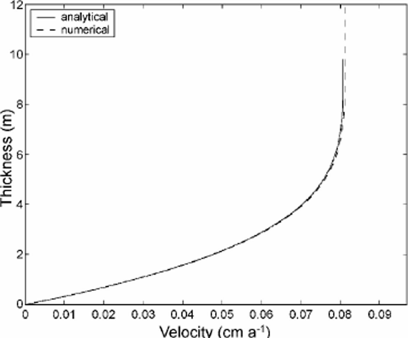
is necessary to avoid a mathematical degeneration of Equation (6) (in case off] = 0). The viscosity is calculated using Equation (7), setting D=1є (with small e). The viscosity is thus equal to the viscosity of undamaged ice multiplied by a factor ![]() Free surfaces are adopted as boundaries for air, and the air density is set to 0. With these assumptions, an accurate solution for the ice flow is obtained. Figure 1 displays the velocity profile through an inclined parallel-sided slab surrounded by air as computed by the numerical model. This profile is compared to that derived from the analytical solution of the problem (Reference PatersonPaterson, 1994). The rheology of broken ice is also described by Equation (6). The viscosity is computed in Equation (7) with D = 1 – є. The densities of ice and of broken ice are assumed to be equal.
Free surfaces are adopted as boundaries for air, and the air density is set to 0. With these assumptions, an accurate solution for the ice flow is obtained. Figure 1 displays the velocity profile through an inclined parallel-sided slab surrounded by air as computed by the numerical model. This profile is compared to that derived from the analytical solution of the problem (Reference PatersonPaterson, 1994). The rheology of broken ice is also described by Equation (6). The viscosity is computed in Equation (7) with D = 1 – є. The densities of ice and of broken ice are assumed to be equal.

Fig. 1. Velocity profile through an inclined parallel-sided slab. Ice is 10 m thick and above it is air. The analytical solution is calculated for ice. The numerical solution is computed for ice and air.
Level-set formulation
To couple the behavior of ice, broken ice and air in a unique computational domain, a level-set formulation is used. The level-set problem is computed for a variable Dls. It describes the position occupied by ice, broken ice and air in time and space. Ice is defined where 0 ≤ Dls < Dc, broken ice where Dls = Dc and air where Dls = 1. Following this definition, the variable Dls has the same value in ice as the damage variable D. Equation (3) is used to describe the evolution of the variable Dls in the ice. Considering the broken ice and the air, the evolution of Dls is described by Equation (2). For incompressible media, the variation in time and space of Dls is described in the whole computational domain as
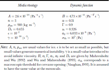
The value of the damage variable D and the density p are deduced from Dls. Table 1 summarizes the parameters used for ice, broken ice and air. Table 2 gives the numerical values of the parameters introduced in the model.
Table 1. Level-set dependent parameters. The level-set function Dls determines the repartition of the different media. The damage variable D affects the viscosity of each medium

Table 2. Values of the model parameters for ice of 0°C

Results
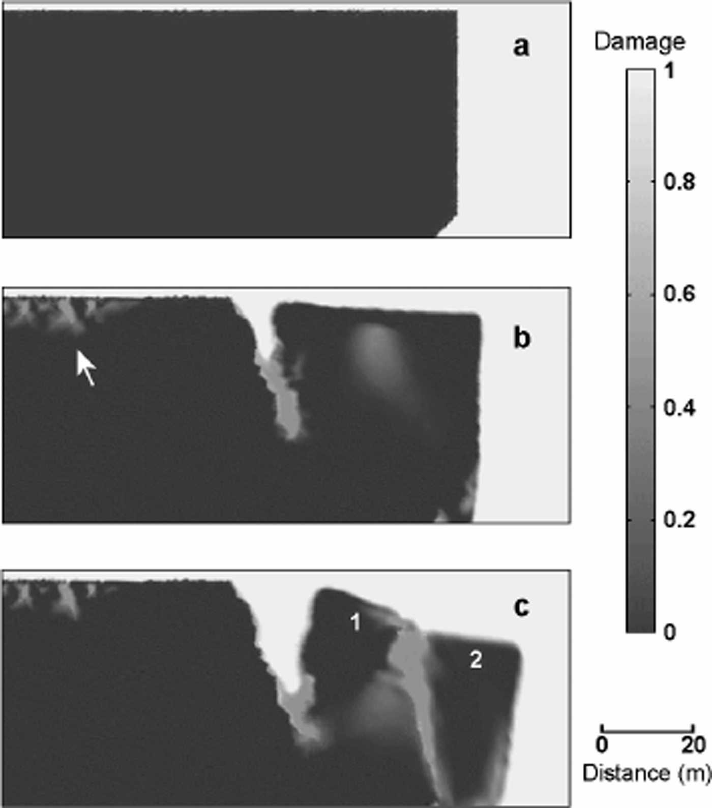
The temporal evolution of a horizontal ice block from an initial undamaged state to the break-off of a part of the block is computed using a two-dimensional finite-element model (FEMLAB 2.2). Figure 2a shows the initial geometry of the ice block. The entire computational domain (ice and air) is also represented. Ice is frozen to the bed (velocity vanishes). Ice may slip on the left border without friction. This boundary condition is expressed as

Fig. 2. (a) Initial geometry of the ice block and global computational domain. (b) Crevasse after 152 days. The arrow indicates the production of damage at the upstream side of the large crevasse. (c) Unstable ice block before failure (199 days). Numbers 1 and 2 indicate the location of the points where velocities are discussed.
where ![]() is the velocity of the ice at the interface with the glacier bed,
is the velocity of the ice at the interface with the glacier bed, ![]() the normal to the bed surface, the tangent to the bed surface and
the normal to the bed surface, the tangent to the bed surface and ![]() the viscous force per unit area at the interface, with a the Cauchy stress tensor.
the viscous force per unit area at the interface, with a the Cauchy stress tensor.
At the beginning of the damaging process, diffuse damage appears at the top of the block (where damage production is maximum). Then, damage concentrates at a point creating a crevasse. With the relaxation of stress, damage which was accumulated on both sides of the crevasse is reduced. The opening rate of this crevasse controls the acceleration of the unstable ice part. Figure 2b shows the state of the ice block after 152 days. After about 180 days, a rapid propagation of a second fracture in the unstable ice part creates a new unstable block (Fig. 2c). This block collapses first after 200 days. Calculation was stopped at this breaking-off event. The formation of secondary crevasses occurring during the separation of the unstable ice mass from a hanging glacier has been often observed in nature (Fig. 3).

Fig. 3. Evolution of an unstable ice chunk detached from a hanging glacier located at the south face of the Monch, Bernese Alps, Switzerland. (a) The large crevasse behind the ice block is well developed (9 June 2000). (b) Two secondary crevasses penetrate in the block (25 July 2000). (c) The block is disintegrated due to the secondary crevasses (1 August 2000).
Discussion
Figure 4 illustrates the velocity as a function of time for the two points indicated in Figure 2c (located in the unstable ice mass) and advecting with the ice during the whole process. The velocity of point 1 (Fig. 4a) increases until the second fracture emerges in the unstable ice block. Then the velocity decreases with stress relaxation due to the extension of this new fracture. Instead, the velocity of point 2 (Fig. 4b) is increasing until collapse. The acceleration of point 2 is compared to Equation (1), which is rewritten as

Fig. 4. Velocity of points 1 and 2 (see Fig. 2c) vs time. (a) Point 1. (b) Point 2.
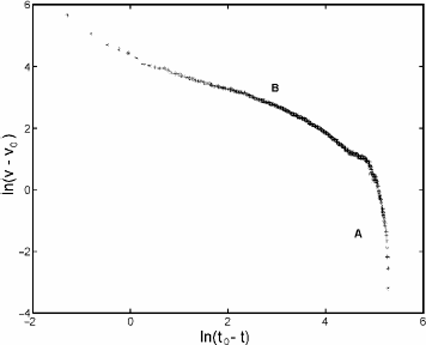
where tf = 200 days and v0 ≈ v(t = 0) are given by the simulation. Figure 5 shows the logarithmic velocity ln(v(t) - v0) as a function of the logarithmic time ln(tf - t) of point 2. The plotted curve is composed of two distinct sections (A and B as shown in Fig. 5) which can be approximated by two straight lines, in accordance with Equation (16). Section A corresponds to the initial damage accumulation before crevasse opening. It represents approximately the first 60 days of the simulation. In the model, D = 0 is applied as initial condition in ice. However, in nature the ice might be already pre-damaged. In Figure 2b, the production of such pre-damage is noticeable at the upstream side of the large crevasse. Therefore, the initial damage accumulation period is expected to be shorter than the modeled one. Section B corresponds to the acceleration of the unstable ice mass due to crevasse enlargement. For this section, comparison of the velocity calculated with the model and that inferred from Equation(16) leads to a correlation coefficient of 0.93. The difference is associated with assumptions on the dynamic function of damage and with numerical errors in the time integration and the finite-element discretization. Comparing the results of the model with the velocity–time function inferred from measurements (Equation (1)), the same behavior has been found. This does not amount to a rigorous validation of the model, but it shows that a local isotropic damage evolution law applied to Glen’s flow law is a promising method for modeling the breaking-off of ice masses from glaciers.

Fig. 5. Logarithmic plot of the velocity of point 2. Time increasing from right to left.
Conclusion
In the present study, the capability of continuum damage mechanics and level-set methods to compute crevasse openings in glaciers is presented. This study does not offer a rigorous validation, but focuses on the similarities observed in nature and computed with the model. Further studies are required to compare the acceleration of unstable ice masses measured on hanging glaciers and simulated with the surface geometry, the bed topography and the ice temperature data of the observed glaciers.
A description of the damage and the level set with a single variable leads to a reduction of the computing time. The disadvantage of this method is an interface between ice and air that is not clearly defined. In the immediate vicinity of the interface, it is not possible to determine whether the gradient of Dls is due to the ice–air transition or damage accumulation. Furthermore, this method does not allow prescription of an accumulation or ablation function at the glacier surface to model the glacier evolution. The level-set and the damage functions have to be described by two separate variables to overcome this limitation. This task is the topic of ongoing research.
Acknowledgements
The authors wish to thank A. Prohl for mathematical support, K. Hutter and T. Schuler for critically reading the manuscript as well as L. Morland, J. Weiss, D. M. Cole and an anonymous referee for their helpful comments and suggestions. This work was accomplished within the GLACIO-RISK project (Survey and Prevention of Extreme Glaciological Hazards in European Mountainous Regions) (grant No. EVG1-2000-00018 and BBW 00.0209-1).


