


Introduction
Image-guided placement of intracranial surface and depth electrodes for the characterization of epileptic foci was first promoted 52 years agoReference Bancaud, Talairach and Bonis 1 and is currently a crucial step in the presurgical evaluation of many patients with pharmacoresistant epilepsy. Stereoelectroencephalography (SEEG) was developed in Paris using a frame-based method that made use of intraoperative angiography to avoid vascular complications.Reference Bancaud 2 The aim of SEEG is to determine the epileptogenic zone—that is, the region of ictal onset and immediate spread—in three dimensions. It was first implemented at the Montreal Neurological Institute in 1972Reference Espinosa, Olivier, Andermann, Quesney, Dubeau and Savard 3 and has been associated with a very low rate of morbidity.Reference De Almeida, Olivier, Quesney, Dubeau, Savard and Andermann 4 , Reference Tanriverdi, Ajlan, Poulin and Olivier 5 The procedure has been in constant evolution to take advantage of advances in materials and innovation in imaging and robotics technology. We began using magnetic resonance imaging (MRI)-compatible electrodes (DIXI Microtechniques, Besancon, France) in 2007 and a Robotic Surgical Assistant (ROSA, Medtech, Montpellier, France) in 2011. Previous studies have shown a greater degree of accuracy with the robot-assisted technique.Reference Chatillion, Mok, Hall and Olivier 6 , Reference Cardinale, Cossu and Castana 7 SEEG electrodes from historical cases were not MRI-compatible, and thus a thorough review of MRI findings was not possible. In our study, for the first time, we showed MRI findings in a relatively large cohort of patients with pharmacoresistant epilepsy who had MRI with electrodes in situ following implantation of SEEG electrodes. We describe the current technique of SEEG implantation at our center and aim to assess its safety and advantages.
Methods
We performed a retrospective chart review of all patients with MRI-compatible intracranial SEEG electrodes implanted by the senior author (JH). The research ethics board of the Montreal Neurological Institute and Hospital approved the review (no. NEU-14-101). All patients had preoperative enhanced MRI for image guidance during implantation of SEEG electrodes as well as postimplantation MRI with the electrodes in situ.
Initially, electrodes were inserted using a frameless technique with a double-chuck articulated armReference Olivier, Boling and Tanriverdi 8 and the StealthStation neuronavigation system (Medtronic, Minneapolis, MN, United States) with image guidance by global acquisition gadolinium-enhanced MRI. Avascular trajectories were chosen from the scalp entry point to the intracranial target. Once the plane was obtained, a percutaneous craniostomy was performed with a 1.3-mm drill bit. A hollow anchoring screw measuring 2.5 cm in length was then secured in place with an adapted screwdriver (DIXI). The neuronavigation system was used to calculate the distance from the tip of the anchoring screw to the target. This distance was then translated to a measuring tool (DIXI), and a stylet (DIXI) was passed through the hollow screw to make a path for the electrode. Coagulation was sometimes required if the dura had not been breached by the anchoring screw. When the stylet was removed, the electrode was inserted to the proper depth and secured to the anchoring screw. The electrodes measure 0.8 mm in diameter.
Since 2011, we used ROSA for stereotaxy and the StealthStation neuronavigation system for verification and for depth measurement in all cases. Avascular trajectories are planned on the ROSA software with image guidance using global acquisition gadolinium-enhanced MRI coregistered onto global acquisition thin-cut computed tomography (CT) angiography (slice thickness=1 mm). The stereotaxic craniostomy, anchoring screw, and electrode placement are identical to that described above.
The anchoring screws are made of titanium and the electrodes are made of platinum and iridium (DIXI Microtechniques, Besancon, France). Preimplantation CT angiography for stereotaxy planning was acquired using a Toshiba CT machine (Aquilion ONE, Toshiba, Tokyo, Japan). Both preimplantation MRI for stereotaxy planning and postimplantation MRI (T1- and T2-weighted images) with electrode in situ was acquired using a 1.5-Tesla magnetic field machine (Signa [GE Medical Systems, Chicago, IL, United States] prior to November of 2014 and Ingenia [Philips Medical Systems, Amsterdam, The Netherlands] thereafter). A T1-weighted image was acquired using the following sequences: prior to November of 2014: slice thickness 1.0 mm, repetition time (TR) 23 ms, echo time (TE) 8 ms, flip angle 20 or 65 degrees; from November of 2014: slice thickness 0.78 mm, TR 7.9 ms, TE 3.5 ms, flip angle 6 degrees). A T2-weighted image was acquired using the following sequences: prior to November 2014: slice thickness 1.2 to 1.6 mm, TR 3.6 to 4.1 ms, TE 1.2 ms, flip angle 20 or 65 degrees; from November 2014: slice thickness 2 mm; TR 2800 ms, TE 475 ms; flip angle 90 degrees).
Postimplantation MRI images with electrodes in situ were employed for evaluation of complications and to reconstruct global images for later use in neuronavigation protocols during resection of the epileptic focus. While there is some metallic artifact, the electrodes and electrode contacts are best visualized on T2-weighted images. T1-weighted images were employed as reference in our neuronavigation protocols, and the T2-weighted images were coregistered.
A total of 55 consecutive patients were identified from September of 2007 to June of 2017. Two patients were excluded from analysis: one because not all of the implanted electrodes were MRI-compatible and postimplantation MRI was not acquired, and the other because it was not performed for SEEG (but for thermoablation). This was done to provide a homogenous cohort of patients undergoing SEEG for pharmacoresistant epilepsy, all of whom had MRI with the electrodes in situ. The MRI images with electrodes in situ were used for image guidance at the time of definitive resection in all patients.
The factors studied included technique of implantation (manual vs. robotic-assisted), radiological morbidity, clinical morbidity, and mortality. We also calculated the MRI-positive rate of patients diagnosed with focal cortical dysplasia (FCD) on histopathology. The MRI findings were extracted from the neuroradiology report of our center based on 1.5-Tesla MRI.
Results
The details pertaining to semiology, MR findings, FDG–PET, and neuropsychology findings of the patients are summarized in Table 1. Both of the techniques described here allowed successful implantation in all cases. Between September of 2007 and March of 2011, 20 patients (11 males; mean age=34.6±9.8 years, range=18–53) were implanted using the manual technique with a total of 184 electrodes (Table 1, patients 1–20). Between July of 2011 and June of 2017, 33 patients (23 males; mean age=30.1±9.4 years, range=14–53) were implanted using the robot-assisted technique with a total of 366 electrodes (Table 1, patients 21–53). Therefore, among the 53 patients included in our analysis, 550 electrodes were implanted, for an average of 10.4 per patient. The duration of implantation ranged from 7 to 31 days, with an average of 14.6 days.
Table 1 Summary of semiology, imaging, neuropsychology data, and preimplantation hypothesis (N=53)
Ant: anterior; Bil: bilateral; C: central; F: female (in the column of gender), or frontal; FC: frontal-central; FCD: focal cortical dysplasia; FLE: frontal lobe epilepsy; Hem: hemisphere; Hc: hippocampus; inf: inferior; L: left; M: male; max: maximum; MTS: mesial temporal sclerosis; mvts: movements; NH: nodular heterotopia; NL: non-lesional; O: occipital; occ: occasional; OF: orbitofrontal; P: parietal; PMG: polymicrogyria; post: posterior; PQ: posterior quadrant; PQE: posterior quadrant epilepsy; Pt: patient; R: right; SGTC: secondary generalized tonic clonic seizure; T: temporal; TLE: temporal lobe epilepsy; UE: upper extremity.
Placement of the anchoring screw requires gentle forward pressure with the screwdriver to secure it to the bone. On two occasions, both associated with the electrodes placed through the temporal bone for hippocampal targets, the screw penetrated the cortex. In these two cases, a 1-cm incision and enlargement of the craniostomy was required to retrieve the screw found at the level of the inner table. While this technical complication resulted in no clinical consequences, its description is mentioned here due to highlight the need for very gentle pressure upon placement. We had no complications associated with removal of the electrodes. In all cases, they were removed with the short-handled screwdriver or the spanner made by DIXI to avoid plunging.
Overall, there was no mortality, no neurologic deficit, and no infection observed. One patient developed headache 3 months after explantation of SEEG electrodes due to a venous thrombosis that resulted in edema in the left parietal lobe. However, an association between implantation and the venous thrombosis is unclear. The patient was treated with anticoagulants for 6 months and is now symptom-free.
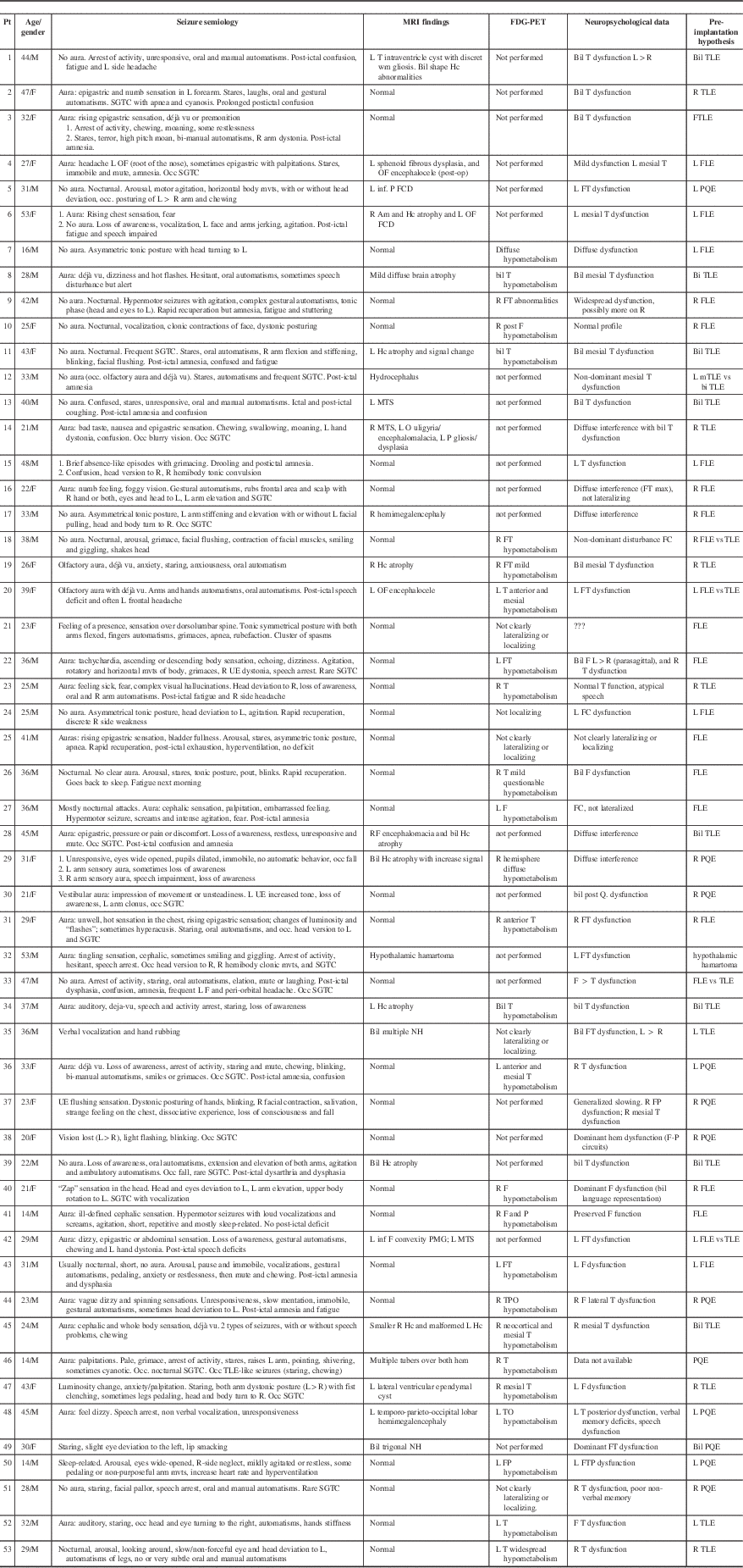
A typical T2-weighted axial image is shown in Figure 1A. When seen along its plane, the electrode and each electrode contact are well-visualized. Figure 1B shows a sagittal T1-weighted image demonstrating the degree of metallic artifact. The actual diameter of the electrode is 0.8 mm.
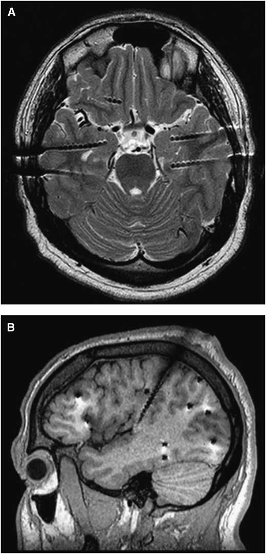
Figure 1 (A) An axial T2 section from an SEEG study for bitemporal epilepsy. When seen along its plane, the electrode and each electrode contact are well-visualized. (B) A sagittal T1 section from an SEEG study for frontal and posterior quadrant epilepsy. Electrodes were aimed at the orbitofrontal, temporal, and occipital areas from a lateral approach and the insula from a superior approach. A metallic artifact (appeared larger than the electrode diameter, 0.8 mm) is appreciated.
A careful review of each patient’s MRI with the electrodes in situ revealed four unexpected findings (three in the manual group and one in the robot-assisted group, p=0.287). Figure 2A demonstrates an area of contusion without hemorrhage that resulted from a penetration of the anchoring screw through bone that had been weakened by previous pin fixation with the manual technique. Figure 2B shows a hemorrhagic contusion that likely occurred from an unintended perforation of the dura and cortex at the time of craniostomy with the manual technique. Figure 2C shows a subdural hematoma that likely occurred from an unintended perforation of the dura and/or laceration of a cortical vessel at the time of craniostomy with the manual technique. Figures 3A and 3B show venous congestion in the left posterior temporal area, most likely secondary to venous compression or coagulation with the robot-assisted technique. Figures 3C and 3D demonstrate its resolution at 3 months post-explantation.
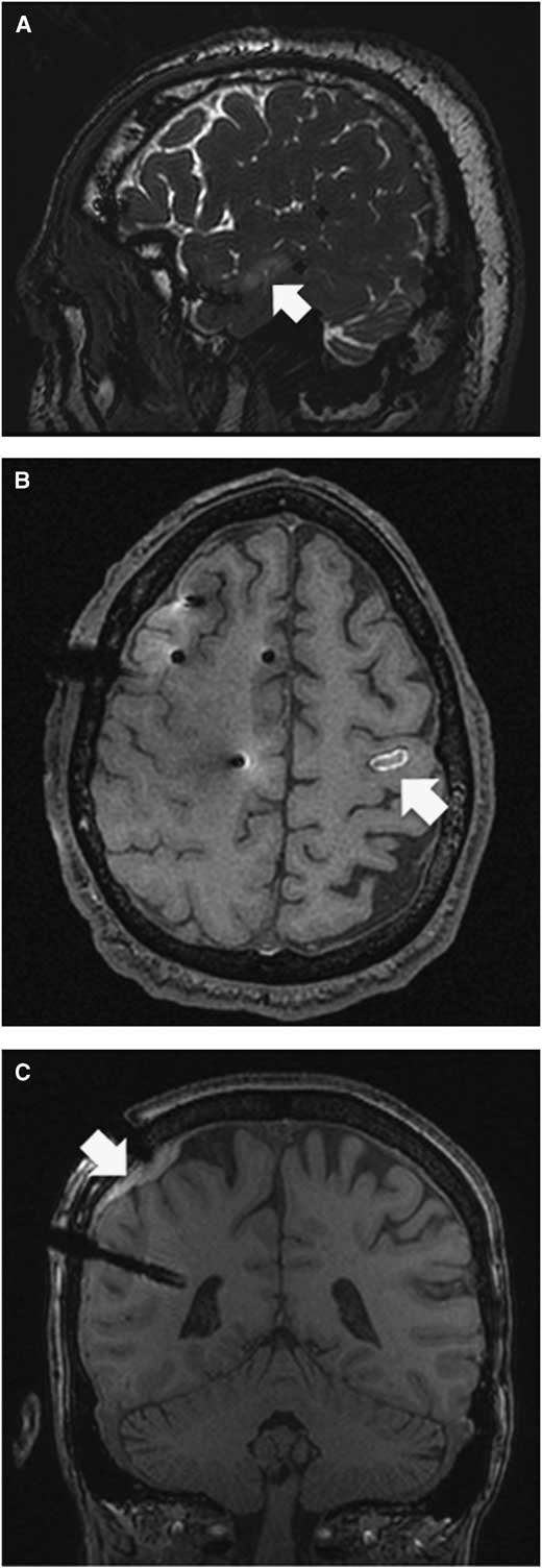
Figure 2 (A) Patient 12. T2 sagittal section showing a non-hemorrhagic contusion (white arrow) on the second temporal gyrus. The bone had been weakened by prior pin fixation where the anchoring screw penetrated the cortex. A small skin incision was required to retrieve the anchoring screw. (B) Patient 17. T1 axial section showing a hemorrhagic contusion most likely due to penetration of the cortex with the drill bit. This was not caused by insertion of the stylet or electrode since it was the intended site of an epidural contact. (C) Patient 6. T1 coronal section showing a subdural hematoma most likely due to unintended penetration of the dura and/or laceration of the cortical vessel.
Figure 3 Patient 34. (A and C) T2 axial section. (B and D) T1 sagittal section. A and B show venous congestion in the left posterior temporal area most likely caused by compression or coagulation of a vein. C and D show these changes to be largely resolved at 3 months post-explantation.
Among the 49 patients in whom the SEEG findings were finalized, 31 (63%) underwent therapeutic intervention (29 resections and 2 thermocoagulations). The MRI images with electrodes in situ were used for neuronavigation in all 29 who underwent resection. Seventeen patients were diagnosed with FCD on histopathology, while only 2 were positive for FCD on multiple preoperative MRI.
Discussion
The goal of the present study is to assess the safety and advantages of the current SEEG electrode implantation methodology in our center. Accuracy of frameless SEEG techniques has been extensively reported,Reference Chatillion, Mok, Hall and Olivier 6 , Reference Gonzalez-Martinez, Bulacio and Thompson 9 , Reference Vakharia, Sparks and O’Keeffe 10 and this is not our aim here.
Among the 53 patients who were implanted for an average duration of 2 weeks, with an average number of 10 electrodes, there was no mortality, no infection, and no new neurologic deficit. This rate of clinical complication is lower than that associated with other types of intracranial recording such as subdural strips or grids.Reference Burneo, Steven, McLachlan and Parrent 11 , Reference Cardinale and Cossu 12 Although the number of patients in this study is relatively small, the low rate of clinical complications with our technique is encouraging, as it is comparable to large series reported recently.Reference Cardinale, Cossu and Castana 7 , Reference Bourdillon, Ryvlin and Isnard 13 , Reference Serletis, Bulacio, Bingaman, Najm and Gonzalez-Martinez 14
Careful review of postimplantation MRI with electrodes in situ revealed four patients with asymptomatic radiological findings on MRI: three in the manual group and one in the robot-assisted group. The overall rate of asymptomatic radiologic complication was 7.54% per patient, or 0.72% per electrode. The overall rate of radiologic complication is slightly higher than that reported in a recent study.Reference Gonzalez-Martinez, Mullin and Vadera 15 However, the modalities used for postimplantation evaluation of complication were different: CT in previous studies and MRI in this study. The difference in radiologic complication rate may be explained by the difference of sensitivity in detecting abnormalities between MRI and CT: MRI (in this study) is more sensitive than CT (in previous studies). Nevertheless, only one hemorrhagic complication was found in this series (1.9% per patient, or 0.18% per electrode) and this rate is the same or even lower than the hemorrhagic complication based on CT findings in previous studies.Reference De Almeida, Olivier, Quesney, Dubeau, Savard and Andermann 4 , Reference Cardinale, Cossu and Castana 7 , Reference Gonzalez-Martinez, Bulacio and Thompson 9 , Reference Gonzalez-Martinez, Mullin and Vadera 15 While the use of robotics in neurosurgery remains in its infancy,Reference Camarillo, Krummel and Salisbury 16 the application to stereotactic procedures is advancing rapidly.Reference Abhinav, Prakash and Sandeman 17 - Reference Gonzalez-Martinez, Vadera and Mullin 19 The present study revealed that robotic assistance is safe to apply to stereotactic procedures.
A novel advantage provided by this technique is the ability to use the MRI with electrodes in situ for image-guided neuronavigation at the time of definitive resection. Under the guidance of MRI with electrodes in situ, resection yielded successful histopathological diagnosis of FCD in 15 patients who were MRI-negative for FCD (88.2% of all patients with FCD in this series). This suggests that neuronavigation using MRI images with electrodes in situ was useful to tailor definitive resection of the so-called “non-lesional” cases, which are often shown to be FCD on histopathology.
The safety of MR imaging of implanted depth electrodes has been a matter of debate.Reference Davis, Spencer, Spencer and Bronen 20 Despite evidence of studies demonstrating its safety under certain conditions,Reference Davis, Spencer, Spencer and Bronen 20 - Reference Duckwiler, Levesque, Wilson, Behnke, Babb and Lufkin 22 postimplantation MRI is still less popular to date because of safety concerns among some neuroradiologists and neurosurgeons. In agreement with previous studies, we did not find any complication after MR imaging in this series of patients. This further supports the safe use of MR imaging in localizing the implanted SEEG electrodes.
Limitations of the Study
While many centers are now moving towards 3-T MR imaging capabilities, the use of 1.5-T MR imaging in our presurgical workup is a limitation in terms of identification of focal cortical dysplasia, or any potential epileptogenic lesion. This may in part explain the patient cohort in whom our preimplantation MRI failed to identify focal cortical dysplasia.
Other limitations include the small number of patients and the retrospective nature of our study. Hence, the safety and complication rate figures reported here need to be taken with caution. The safety of our SEEG implantation methodology and the usefulness of MRI with SEEG in situ in clinical practice will be better demonstrated in a larger controlled prospective study.
Conclusions
We reported the technique, safety, and advantages of the current SEEG implantation methodology in our center. This is also the first reported series of MRI findings of patients with SEEG electrodes in situ. While the radiological changes were few and none were clinically significant, it nonetheless suggests that we should remain vigilant in refining the technique and restrict the number of electrodes to the minimum required to study a well-defined preoperative hypothesis regarding the seizure onset zone and propagation pathway. The use of MRI-compatible electrodes allows neuronavigation using the images with the electrodes in situ, which is useful to tailor the eventual definitive surgical resection.
Acknowledgments
HMK is supported by a Mark Rayport and Shirley Ferguson Rayport fellowship in epilepsy surgery and was supported by the Preston Robb fellowship of the Montreal Neurological Institute, a research fellowship of the Uehara Memorial Foundation (Japan), and travel grants from the Osaka Medical Research Foundation for Intractable Diseases (Japan) and the Japan Epilepsy Research Foundation.
The authors thank Dr. J. Gotman and Dr. E. Kobayashi of the Montreal Neurological Institute and Hospital for their financial contributions (from their research grants) to partially offset the cost of the electrodes, Dr. M. Cortes of the Montreal Neurological Institute and Hospital for her professional advice and technical support in MRI sequences, and Dr. F. Dubeau for his professional support in retrieving detailed clinical data.
Disclosures
Dr. Khoo received support from a Mark Rayport & Shirley Ferguson Rayport Fellowship in Epilepsy Surgery of the Montreal Neurological Institute and Hospital during the conduct of the study; and support from a Preston Robb fellowship of the Montreal Neurological Institute, the Uehara Memorial Foundation (Japan), the Osaka Medical Research Foundation for Intractable Diseases (Japan), and the Japan Epilepsy Research Foundation outside the submitted work.
Dr. Hall has nothing to disclose.
Statement of authorship
JAH was responsible for conception and design of the study. JAH and HMK were responsible for acquisition and analysis of data, drafting a significant portion of the manuscript, and the figures.


