


Introduction
Ice sheets play a major role in controlling the Earth's sea level. Our ability to predict future change is limited by our lack of understanding of ice sheet physics and uncertainty over how ice sheets behaved during past climate cycles (IPCC, 2019). With the majority of ice leaving the ice sheet through fast-flowing ice streams and outlet glaciers into adjacent ice shelves, these dynamic features are likely to be the fastest responding component of the ice-sheet system. Understanding the controls on ice stream flow is clearly important if we are to reduce the uncertainties in our projections of future ice-sheet evolution in a changing climate.
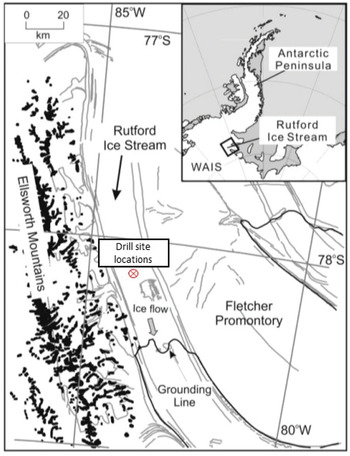
A British Antarctic Survey (BAS) led project in collaboration with Swansea University, ‘Basal conditions on Rutford Ice Stream: BEd Access, Monitoring and Ice Sheet History’ (BEAMISH) aims to understand this glacier's dynamics and the ice sheet's regional history. Rutford Ice Stream is a fast-flowing glacier that occupies a deep trough, draining ~49 000 km2 of the West Antarctic ice sheet into Ronne Ice Shelf. It is bounded by the Ellsworth Mountains to the west and Fletcher Promontory to the east, is over 200 km long, 20–25 km wide (Fig. 1) and flows with a surface ice velocity of almost 400 m a−1 (Doake and others, Reference Doake, Richard and Alley2001). Many field parties have worked on Rutford Ice Stream since 1978, resulting in a good, broad understanding of its geometry and dynamics. More recent fieldwork has undertaken the detailed mapping of bed topography and subglacial landforms (King and others, Reference King, Pritchard and Smith2016), mapping the ice/bed interface characteristics (Smith and others, Reference Smith2015) and a time series of the seismic profile that crosses one of the drill site locations (Smith & Murray, Reference Smith and Murray2009).
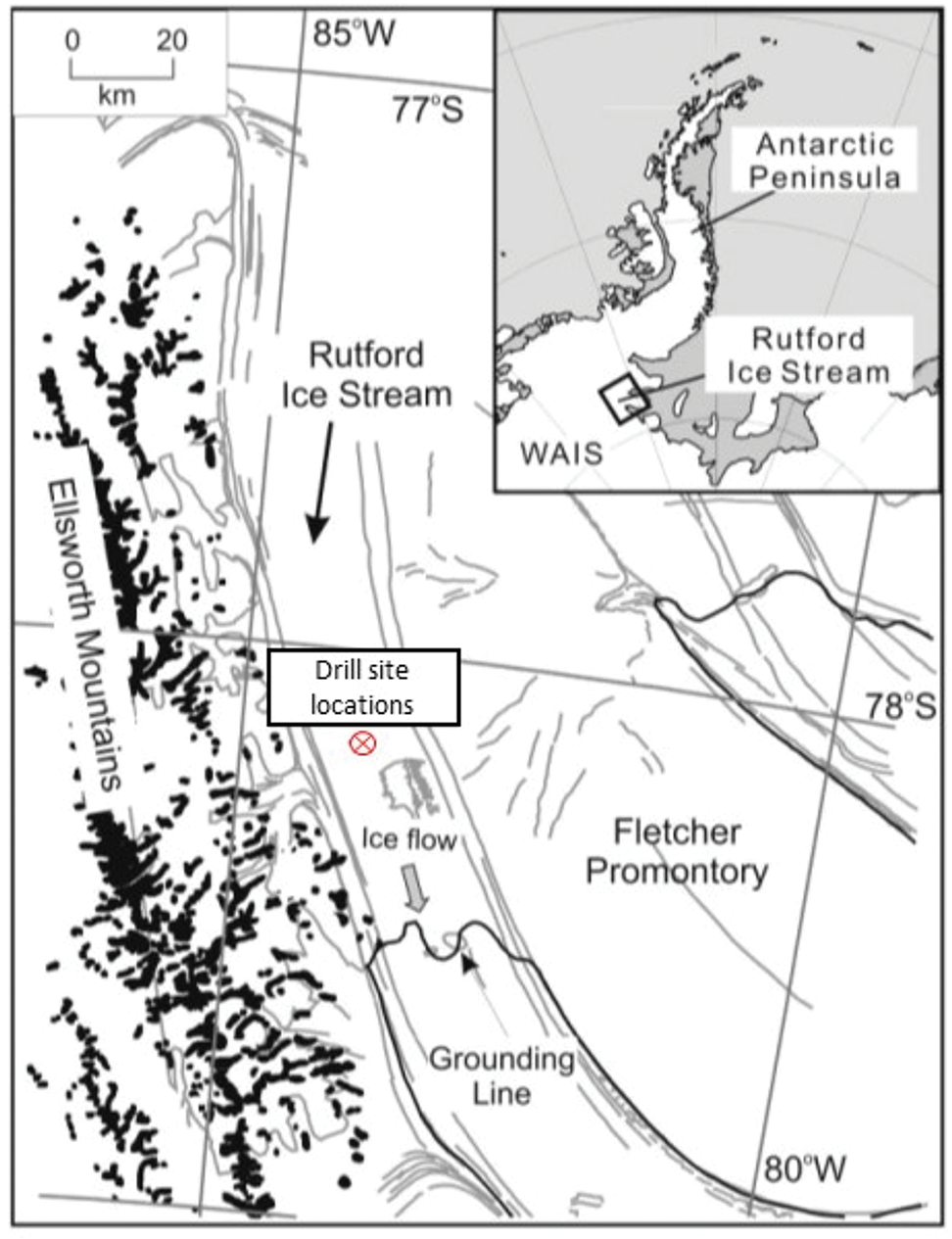
Fig. 1. Location of BEAMISH drill sites on the Rutford Ice Stream.
To enable retrieval of sediments to help constrain ice-sheet history and to allow the installation of instruments into the ice and bed to monitor ice stream flow, hot-water drilling (HWD) offers one of the fastest methods in the creation of access holes through thick ice (Talalay, Reference Talalay2020). As part of the broader BEAMISH project, the aim was to drill a total of four holes at two locations, ~2 km apart, to sample the underlying sediments and to instrument the ice and the basal sediment (Smith and Fothergill, Reference Smith and Fothergill2016). For this to be achieved within a single Antarctic field season, HWD was the method of choice to rapidly create access holes for the BEAMISH project.
In 2004/05, a similar project, RABID, attempted to access the bed of Rutford Ice Stream. Here a HWD system drilled to within ~100 m of the ice stream base, until a hose failure forced operations to stop (Smith, Reference Smith2005). This hot water drill system, based on the standard BAS design (Makinson, Reference Makinson1993), delivered 135 L min−1 of water at 85–95°C through 2200 m of 1.25″ bore thermoplastic hose, assembled from 200 m sections. A union between these sections failed, with the loss of over 1900 m of drill hose. Subsequently, HWD systems designed and operated by BAS aim to have as few sections of hose as possible and ideally one single length (Makinson and Anker, Reference Makinson and Anker2014).
With over three decades of HWD experience in Antarctica and significant engineering and logistical facilities, BAS was well-positioned to deliver a drilling system capable of accessing the base of the Rutford Ice Stream. In recent years, BAS HWD capabilities have grown significantly. The new modular BAS Ice Shelf Drill (ISD) 500 m system was successfully used on the Larsen C and George VI ice shelves in 2011/12. The same drill system, upgraded to a 1000 m configuration (Makinson and Anker, Reference Makinson and Anker2014) was used on Ronne Ice Shelf in 2014/15 to drill three holes through up to 775 m of ice (Nicholls, 2018). Following minor improvements to logging and winching systems, and improved provision of spare components, the system was used during the 2015/16 and 2016/17 seasons as part of the Filchner Ice Shelf System (FISS) project, to drill a total of seven ocean access holes, up to 915 m deep, through the Filchner Ice Shelf (Huhn and others, Reference Huhn2018). This fieldwork allowed the refinement of HWD procedures, the training of system operators and the resilience testing of several components which were integrated into the BEAMISH HWD design.
The >2 km thickness of Rutford Ice Stream poses a significant challenge to the HWD process. Apart from the BAS RABID HWD system, only two HWD systems have drilled deeper. The AMANDA (Koci, Reference Koci1994) and IceCube projects (Benson and others, Reference Benson2014), both located at the South Pole, drilled to depths of 2400 m and 2500 m, respectively. Neither system was used to penetrate the ice sheet; rather, the 60 cm diameter holes were used to construct the IceCube Neutrino Observatory. These large-scale operations ran over several consecutive years, drilling up to 20 holes in a single season (Benson and others, Reference Benson2014). As part of the drilling operations, the IceCube drill used an instrumented drill head, returning real-time hole diameter and drill nozzle positional data over the full depth of the borehole. These measurements indicated that straight, vertical boreholes are achievable over depths in excess of 2000 m using the HWD method.
The identification of Subglacial Lake Ellsworth (SLE) in West Antarctica as a candidate for exploration (Siegert and others, Reference Siegert2004), led to the design and construction of a HWD system capable of cleanly drilling through the 3155 m thick ice overlying the lake (Siegert and others, Reference Siegert2012). In December 2012 however, the drill system suffered several significant equipment failures, leading to the abandonment of drilling operations. This event led to a formal, independent failure review process being commissioned by the funding body, the National Environmental Research Council (NERC). The resulting Failure Review Board (FRB) report (Benson and others, Reference Benson2013) identified many SLE specific issues and provided several recommendations for future deep HWD operations with the SLE clean hot-water drill system (Siegert and others, Reference Siegert, Makinson, Blake, Mowlem and Ross2014). The BAS ISD already addressed many of the SLE-specific issues, for example by using multiple heaters, multiple system sensors, electric drive winches and repairable umbilicals (Makinson and Anker, Reference Makinson and Anker2014). However, further field tests were undertaken in subsequent years to improve equipment and processes for reliably forming wide, interconnecting subsurface cavities, which were integrated into the BEAMISH HWD design.
Access to the Rutford Ice Sheet bed facilitates the wider scientific sampling program of BEAMISH, focussing on both the nature of the underlying sediment and the dynamics of the overlying ice. Sediment rheology is assessed from the installation of an instrumented subglacial plough which is deployed through the borehole and driven into the basal sediment. Following refreezing of the borehole, the plough is forced through the sediment by the downstream ice movement, with integrated strain gauges inferring shear properties of the sediment. A sampling of the sediment is carried out using a standard gravity corer with hammering mechanism (Makinson, Reference Makinson2021), recovering 63 mm diameter samples. Tiltmeters in discrete pressure housings are deployed in strings of multiple instruments within the ice borehole. Once frozen into the ice, the instrument packages monitor ice dynamics through the thickness of the ice sheet. Smith (Reference Smith2020) provides further details of the scientific program and an overview of the BEAMISH project and fieldwork; here we present the BEAMISH HWD system that was used to provide the required subglacial access holes and give details of its design, the drill equipment and subsystems and its field operation.
HWD system overview
The BEAMISH hot-water drill system was designed to provide a 300 mm diameter hole through 2200 m of grounded ice. It uses a scaled-up version of the standard BAS hot-water drill system (Makinson and Anker, Reference Makinson and Anker2014) to supply 140 L min−1 of water at >85°C and up to 7000 kPa.
The main components of the BEAMISH HWD are:
• Four 250 kW Avtur powered water heaters with a Heat Recovery System (HRS)
• Four 5.5 kW reciprocating Cat pumps
• Seven 15 kVA three-phase petrol generators
• 2300 m 1.25″ hose and associated storage winch
• Winch tower with capstan and sheave arrangement
The heaters, pumps, and generators are arranged on a 22 m long, 12 mm thick polyethylene polysled for transport and operation. The system was assembled on the Rutford Ice Stream as shown in Figure 2.Figure 2 to be placed after the text of section 'HWD System Overview'
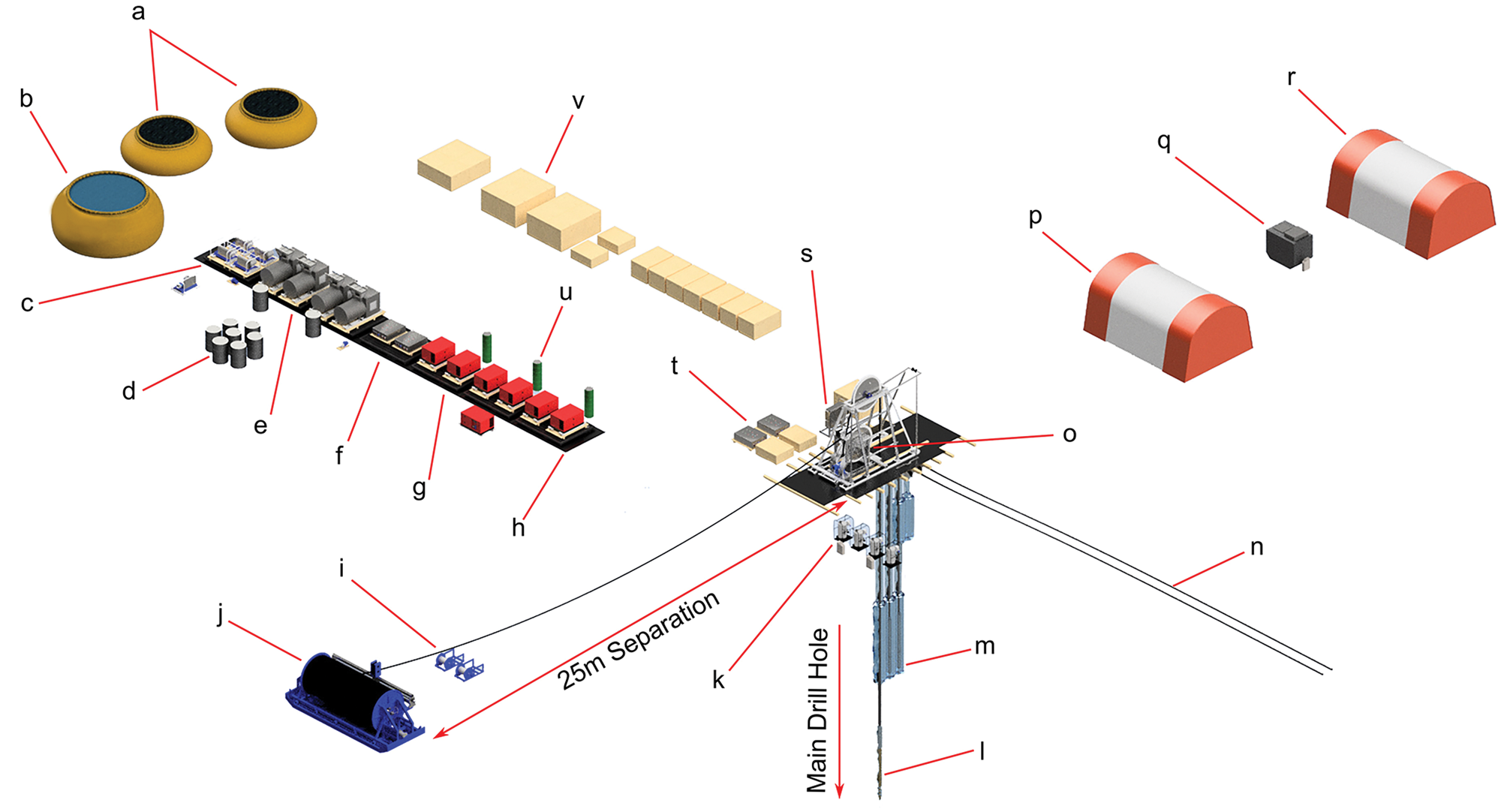
Fig. 2. Isometric CAD view of BEAMISH drill site, detailing individual components and their relative locations to scale. (a) 2 × 10 000 L water storage; (b) 30 000 L water storage; (c) 4 × Cat pumps + 1 spare; (d) Heater fuel depot, 205 L Avtur drums; (e) 4 × 250 kW water heaters; (f) 2 × Cat pump control panels; (g) 6 × 10 kW generators + 1 spare; (h) Polyethylene Polysled 72′ × 8′ × 12 mm; (i) Sediment coring winch + 1 spare; (j) Hose reel winch + 2300 m drill hose; (k) 2 × Secondary heaters + 2 spare; (l) Drill nozzle with weight stack (shown below the surface); (m) Deep cavity with 2 × borehole pumps deployed (shown below the surface); (n) 2 × Umbilicals, shown in pre-deployment position; (o) Winch tower and capstan drive; (p) Work tent; (q) Snow melter, seed and domestic water; (r) Domestic-mess tent; (s) Winch control panel; (t) 2 × Borehole pump control panels; (u) Generator fuel supply, 60 L petrol drums; (v) Shipping crate lids as work surfaces.
The need to preserve the basal sediments for sampling requires management of the water level within the borehole so that the borehole pressure closely matches basal water pressure under the ice stream. Predictions for the water level depth on basal breakthrough ranged between 200 m and 275 m below the surface. Two 9.2 kW borehole pumps are therefore used to ensure sufficient recovery of drill water from this depth range throughout the drilling procedure. The associated 330 m long umbilicals, constructed from hoses and cables, were assembled on site.
To provide greater logistical flexibility, all components of the BEAMISH HWD, except the hose winch and 2300 m main drill hose, can be disassembled and transported by Twin Otter aircraft if required. The majority of the system components can be stored in typical Antarctic winter conditions found on the Rutford Ice Stream. Before overwintering, antifreeze is used to flush any water from the system and sensitive electronic components are removed from the larger control panels.
3-D Site modelling
Each large component of the system was dimensionally imaged within 3-D parametric CAD program, Autodesk Inventor. By having each component available as a 3-D file, an accurate representation of the drill site was constructed within the program's assembly environment (Fig. 2). This proved valuable in designing site layout, effectively positioning equipment with respect to other dependent components, allowing the correct dimensions of power and instrument cables, and water and fuelling hoses. The potential effect of wind-blown snowdrifts from equipment could also be anticipated and prepared for with respect to prevailing wind conditions.
Planning and logistics
The BEAMISH drill system was transported to the location on Rutford Ice Stream using BAS logistics, with the drilling hose and winch shipped to Ronne Ice Shelf during the 2013/14 season by the Royal Research Ship Ernest Shackleton with additional equipment shipped on the RV Polarstern. Subsequent years saw repeated inputs with equipment and fuel transported to the drill site using the BAS PistenBully-based tractor traverse. The full weight of the system was ~25 T, excluding fuel.
A PistenBully vehicle with a Hiab crane and operator-mechanic was available for all onsite operations. This was an essential tool for cargo handling, transporting equipment between sites and in the deployment and recovery of downhole equipment.
The majority of the water heating and power supply plant was mounted, transported and operated from a 22 m long polysled. Seven steel, gridded pallets were secured to the polysled and drill equipment mounted on top. Large items were shipped in individual wooden crates, allowing them to be quickly and easily covered and protected from poor weather while on-site, with the crate lids proving useful work surfaces.
Avtur fuel, suitable for use in tractors, aircraft and the HWD was transported in a number of 5678 L flexible fuel ‘bladders’, with ~41 000 L available for drilling on the Rutford Ice Stream. Drill generator petrol was supplied in 60 L or 205 L drums, totalling 11 420 L available.
To minimise risk to the project, a test season was programmed into the BEAMISH project for the 2017/18 Antarctic season. A small team, ranging from two to five were deployed to the planned drill site location on the Rutford Ice Stream (S78o 08.231′, W083o 55.825′) and undertook critical tasks during the month-long deployment. Tasks included verifying the presence of all items, checking the condition of equipment which had wintered for multiple seasons, assembling drill equipment and familiarising with drill operations. A 20 m deep hole was drilled to test various components of the drill system and verify operational procedures. The test hole also allowed training in the assembly and deployment of downhole equipment. The test season proved critical to the success of the deep drilling on Rutford Ice Stream in the 2018/19 field season. The inclusion of a commissioning test season is highly recommended when using new HWD systems.
Generator-Pump-Heater circuits
An important design feature of the BEAMISH HWD was the arrangement of the primary water supply components. Four identical generator-pump-heater circuits are run in parallel with the resulting hot water outputs brought together at a common, instrumented manifold, feeding the main drill hose (Fig. 3). Each circuit was able to run independently, with each generator providing power to a pump and heater. This arrangement gave significant redundancy in the event of failure of any component. By isolating the affected circuit, the system could continue to run at 75% capacity while the problem was resolved, with drilling speed reduced to account for the reduction in hot water output. A spare generator and pump were immediately available to be swapped into any circuit if needed, allowing the repaired circuit to be reintegrated into the main system, returning performance to 100%. Typically, however, each generator-pump-heater circuit operated at 85% capacity. Therefore, during a circuit failure, the remaining three circuits could be brought to full capacity, meaning that the actual drill capacity only reduced to 88%.
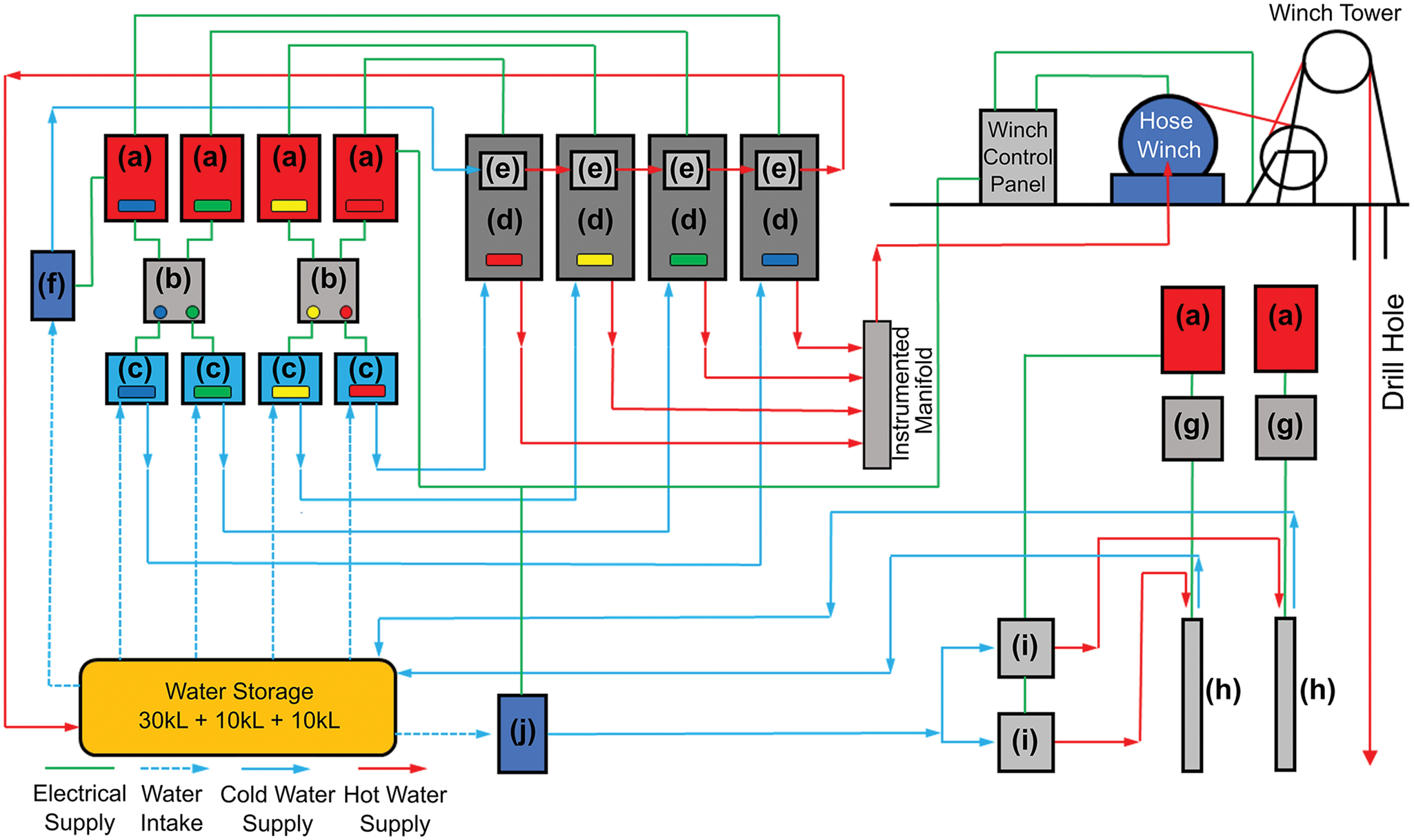
Fig. 3. Schematic of water flow and power supply circuits of the BEAMISH hot-water drill system. Note the four, colour coded generator-pump-heater circuits. (a) Generator, 10 kW; (b) Cat pump control, 2 × 7 kW; (c) Cat pump, 5.5 kW; (d) Primary water heater, 240 kW; (e) Heat recovery system; (f) Axial pump, 0.9 kW; (g) Borehole pump control, 11 kW; (h) Borehole pump, 9.2 kW; (i) Water heater, 60 kW; (j) Axial pump, 1.1 kW.
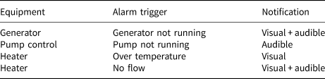
Simple alarm systems were installed in all major components of the generator-pump-heater circuits (Table 1), immediately alerting operators to significant failures and aiding rapid fault finding.
Table 1. Generator-pump-heater circuit alarms
A simple colour coding system (see Fig. 3) was used to quickly and easily identify which generator-pump-heater circuit each unit, cable or hose was part of. This greatly improved the speed of fault finding and rectification.
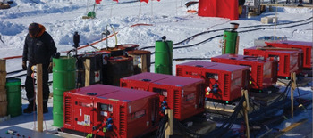
Generators
Six 10 kW/15 kVA 3-phase Europower petrol generators (Fig. 4) provide electrical power to the drill system and were originally chosen for BAS HWD operations as they supply the greatest power-to-weight ratio in a unit that would fit within a Twin Otter aircraft. The Honda GX690 engines within each generator proved reliable, running uninterrupted for over 4 days at up to 90% rated power. Typical power draw for each generator running a generator-pump-heater circuit was 6.8 kW. Over the three-hole drilling periods throughout the 2018/19 field season, each generator ran for an average of 250 h.

Fig. 4. Main generator bank of the drill system. Note the raised fuel supply drums providing positive pressure to the generator fuel pumps.
Each pair of generators was supplied from a 60 L drum that was raised 0.3 m to provide greater head pressure to the generator fuel pump. Simple level gauges in each 60 L drum gave an indication when refuelling was required.
Problems associated with condensation freezing within generator carburettors during cold, overnight periods caused very occasional power supply issues. A standby generator was always available in the event of online generator failure.
Primary heaters
The four primary heaters of the BEAMISH system (Fig. 5b) were to an identical design to those used in the BAS ISD system, as detailed by Makinson and Anker (Reference Makinson and Anker2014)
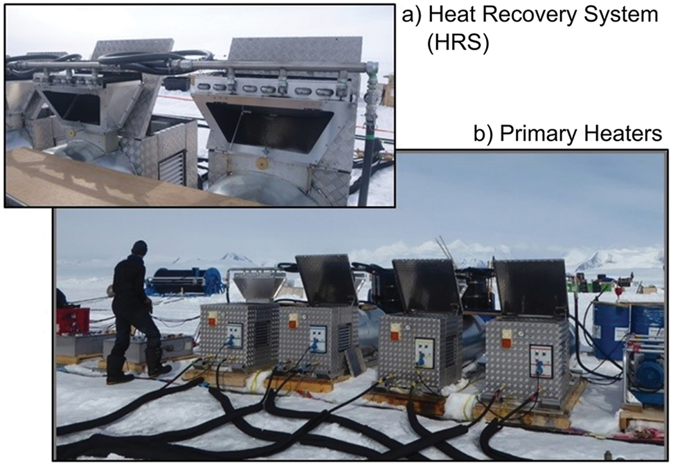
Fig. 5. Primary heater units (b) and heat recovery units (a) mounted on heater exhausts with bypass vents open.
Each heater consists of a 100 m long, 19 mm ID stainless steel double coil tube heat exchanger rated to 7000 kPa, heated by a single 250 kW NuWay MOL 350 oil burner consuming ~0.45 L min−1 Avtur at a fuel pressure of 900 kPa. The full system heating capacity is 1 MW, able to heat 160 L min−1 by 90°C. Typically, the system operated at 140 L min−1 at 88–95°C with a min-max ΔT of 78–90°C. Each burner consumes ~22 L h−1 Avtur for a total system consumption of a 205 L drum every 2.4 h. To provide additional lubricity for the burner fuel pumps, 2-stroke oil was added to the Avtur at a 1:200 ratio.
Cleanliness and efficiency of heater operation was adjusted by varying burner airflow, modifying fuel supply pressures, or changing fuel spray nozzle pattern and capacity. A Kane 250 combustion analyser was used to test each heater exhaust.
Heat recovery system
Significant heat is lost from the exhaust of each primary heater unit; therefore, a simple Heat Recovery System (HRS) was installed to improve system efficiency and reduce fuel consumption. Each HRS unit consists of three domestic heat exchangers, positioned 300 mm above the exhaust of each primary heater (Fig. 5a) and supplied with water from the main storage flubber by a 0.9 kW centrifugal pump. Each heat exchanger was linked in parallel with its neighbour and the resulting heated water returned to the flubber. The heater exhaust temperature before the HRS was ~350°C, which reduced to 130–250°C after the heat exchanger. With the HRS assembly positioned high on the heater exhausts, it is exposed to sufficient wind effects which subsequently produce this large range of temperatures. The average water temperature increase across the system was between 15 and 18°C and with a flow rate of 35–40 L min−1 so that 37–50 kW was recovered. This pre-heated the flubber and increased the primary heater output by 5–10°C.
A failure in the water supply to the HRS can lead to airlocks. To prevent the heat exchangers overheating, flaps were used to temporarily divert the heater exhaust away from the heat exchangers, allowing them to cool and ease re-priming.
Main system pumps
The main pumping system comprised four positive displacements, triplex pumps, identical units to those used in the previous ISD system (Makinson and Anker, Reference Makinson and Anker2014). Each 1531 model Cat pump was specified with a stainless-steel manifold, suitable for long term storage and a 5.5 kW three-phase motor geared such that the pump supplied 39 L min−1 at 7000 kPa pressure through a belt and pulley. Each pump was run at 90% speed to supply 35 L min−1 for a total system flow rate of 140 L min−1.
Separate pressure regulator and safety relief valves were mounted from the pump outlet port on a 2 m long hose. A pulsation dampener was also installed on the outlet to smooth fluid vibrations. Each pump had its own clear hose suction intake to the 30 000 L flubber tank so that the water flow could be seen while priming. Each intake had a foot strainer to prevent entrainment of debris and fouling of pump intake valves Figure 6.
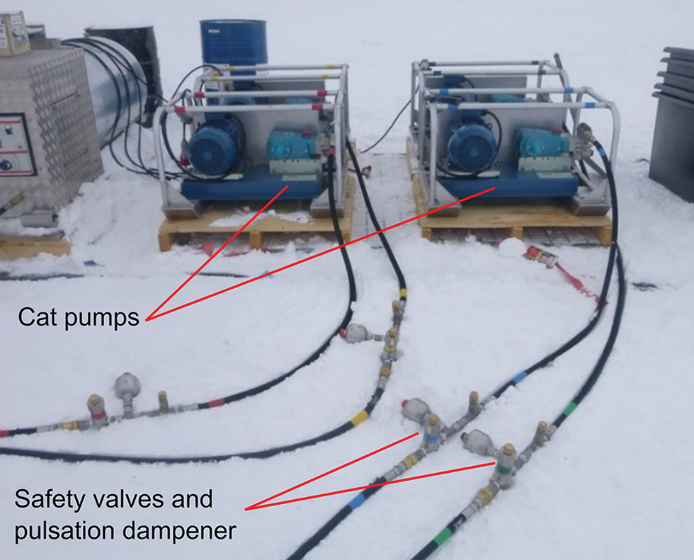
Fig. 6. Cat pump units with pressure relief safety valves and pulsation dampeners on hose tails.
Pump control
Lenze SMD inverters in custom stainless-steel enclosures provided speed control to motors in both the reciprocating Cat pumps and the downhole borehole pumps. Both pump types were driven by oversized inverters, allowing the use of inline chokes and sine filters which drew a small proportion of power but provided additional protection to the equipment. Over-rated inverters also gave flexibility over the use of longer power cables from the controller to pump, and especially valuable over the 330 m cable lengths of the borehole pump power cables (Table 2).
Table 2. Pump motor and inverter ratings
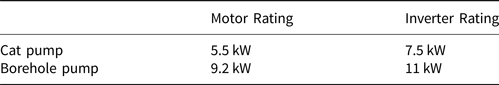
The inverters proved particularly robust, successfully overwintering at temperatures below −40°C. In operation, they can handle transient overloading conditions and occasional power downs, buffering power and restarting the pumps in high load circumstances. An alarm, added to each pump control inverter relay, indicating a ‘motor not running’ condition, proved useful for the submersible borehole pumps, as they were difficult to monitor.
Winching system
The 2300 m of drill hose was lowered and raised using a bespoke winching system designed and built by Able Engineering Ltd, UK. It comprised two separate units, the hose drum winch, and the drill tower with a driven capstan and follows the design of the ISD winch system (Makinson and Anker, Reference Makinson and Anker2014).
Hose drum winch
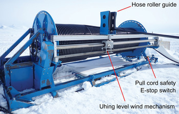
The hose drum winch (Fig. 7) held the 2300 m drill hose and provided back tension for the operation of the capstan drive. It was driven by a 1.5 kW three-phase motor through a 1:56 ratio gearbox and 1:4.1 pinion and ring gearing to give a maximum spooling speed at full diameter of 10.7 m min−1. The motor had an integral brake to hold the hose in the event of a power down, with forced ventilation allowing operation at slow or zero speed and a shaft-mounted encoder, which integrated with inverter control to allow both speed and torque control. A rotary coupling allowed free rotation of the drum at the water inlet point. On its own, the winch weighs ~3250 kg, but ~4900 kg when loaded with 2300 m of drill hose.

Fig. 7. Hose drum winch showing the Uhing level wind mechanism.
To ensure safe operation of the winch, a pull cord emergency stop was installed around the base of the winch skid (Fig. 7). This could be kick operated and would trigger in the event of an individual trapping a body part beneath the hose during hose-recovery. To further increase safety a level wind mechanism automatically laid the hose neatly on to the drum. The infinitely variable, three-ring design from Joachim Uhing GmbH was driven from the winch gearbox and traversed the hose roller guide along the drum. The unit allowed the lay-up ratio to be easily changed as the diameter of the hose varied due to changes in tension, and water pressure and temperature.
The winch was mounted on a skid base allowing it to be directly towed short distances and the 2 km between the two BEAMISH drill sites. Greater distances required the winch to be transported on a Lehmann sledge with significant bracing of the drum needed to limit lateral movement and potential damage to bearings.
Capstan driven tower
A three-quarter wrap capstan drive unit was powered by a 2.2 kW three-phase motor with integral braking, forced ventilation and a shaft-mounted encoder. The two-stage gearbox gave a total reduction of 1:500. With a 150 kg nozzle weight and the additional weight of 235 m of water-filled hose hanging in air, the capstan had a maximum speed of 9.1 m min−1 while retaining the ability to drill at a minimum controllable speed of ~0.1 m min−1.
The idle sheave wheel had a clearance height of 3 m above the borehole opening and was instrumented with a rotary encoder and two 10 kN load cells mounted at the end of a cantilevered frame, which held the wheel. Both instruments fed to panel meters on the winch control panel to give readouts of hose traverse distance or depth, and traverse speed and the weight of the hose down the hole.
The aluminium tower construction integrated an extended height jib to facilitate the deployment of borehole pumps into the holes. A 12 v truck winch was mounted on the capstan skid with the line running over the sheave wheel and jib roller to aid in lifting the pumps into position.
Creating three boreholes parallel to each main drill hole (See section Cavity Creation) required the tower to be easily and accurately moved between hole positions. A foundation was constructed using 12 mm thick phenolic plywood secured to half-buried 4″ × 4″ wooden beams. Manual Tirfor hand winches rated at 8 kN and secured to snow anchors, were used to tow the tower along its longitudinal axis into position. The tower was mounted on two aluminium skids to ease this process Figure 8.

Fig. 8. Winch tower showing instrumented sheave and capstan drive.
Winch control panel
The winch control panel housed Lenze highline inverter drives that controlled the winch motors. With positional output from the motor shaft encoders, precise speed and torque control was achieved using the front-mounted potentiometer dials. As the number of hose layers reduced during drilling, the hose tension could be maintained by the precise torque adjustment. Accurate speed control on the capstan guaranteed consistent drilling speeds. Red Lion PAX2 panel meters output an RS485 signal to the monitoring system, displaying drill speed, depth and load from the instrumented sheave.
The control panel integrated the winch safety systems, with a safety relay controller that monitored three emergency stop switch locations across the site and also the alarm system, which was triggered by setpoints assigned to the various PAX2 panel meters.
A Panasonic Toughbook laptop displayed the drill monitoring software and was positioned on the control panel to allow easy modification to winch parameters while viewing the monitor display Figure 9.
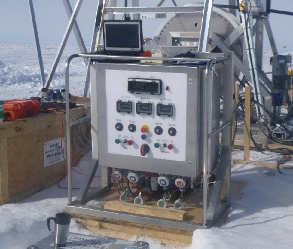
Fig. 9. Winch control panel positioned in front of winch tower during drilling operations with Toughbook computer displaying drill-monitoring data.
Drill hose
A previous drilling project on Rutford Ice Stream was unsuccessful when a hose coupling failed, with the loss of ~2000 m of drill hose (Smith, Reference Smith2005). To eliminate couplings from the drill hose, a single 2300 m length drilling hose was specified, together with a spare in case of damage during transit or drilling. The 6 mm wall thickness of the hose comprises an extruded nylon PA11 core, a Kevlar over braid and extruded Hytrel sheath, with the construction weighing 0.72 kg m−1 in air. The Hytrel coating was specified for its good winching properties, as it does not stick to itself and it increases hose density to prevent it from floating in the water-filled borehole. However, when filled with 85°C water, the hose is slightly buoyant, with small drill water temperature changes producing observable changes in the hose buoyancy. To retain compatibility with existing heating and pumping infrastructure, the 1.25″ bore hose was chosen to keep the operating pressures below 7000 kPa or 50% of its maximum working pressure. As the hose operates under tension, the manufacturer undertook a series of tensile tests on the pressurised hose up to the maximum expected load of 920 Kg, with a typical maximum strain of 9%.
Nozzle
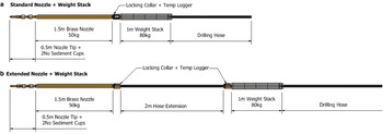
The 50 kg drill nozzle, consisting of a 1.5 m long, 3″ diameter brass tube with a 1″ bore, was effectively a heavy plumb weight, ensuring the hole was drilled straight and vertical. Several factors such as hose and hot water buoyancy, thrust from the high velocity drill nozzle water jet and friction with the hole sides can all reduce the effective weight of the nozzle during drilling, leading to a hole that is neither straight nor vertical (Smith, Reference Smith2005). An additional concern at BEAMISH was curve memory of the drill hose. Stored on the winch in excess of 4 years, some curvature could be retained during drilling, causing the drill to deviate off centre. To counter this, an additional 80 kg stainless steel weight stack was added to the nozzle, bringing the total weight to over 135 kg (Fig. 10a). To reduce the loading on the hose swage fitting above the nozzle, plaited grips made from 6 mm Kevlar rope were connected to eyes on the weight stack via turnbuckles. The grips distribute the weight along 600 mm of the drill hose with tension applied by tightening the turnbuckles.

Fig. 10. (a) Sketch of the drill nozzle coupled directly to the weight stack and (b) the extended drill nozzle configuration.
The increased diameter of the nozzle weight stack led to problems with forward drilling progress. The annular gap between the developing hole and the 120 mm diameter weight stack, restricted return water flow back up the borehole. This restriction caused an observable reduction in hose tension at the surface, presumably as the upward water flow lifted the nozzle and weight stack. Under these conditions, the drilling speed was limited to <1 m min−1. This issue was resolved by adding a 2 m length of drill hose between the drilling nozzle and weight stack (Fig. 10b). The extension provided extra time for additional melting to increase the borehole diameter sufficient to allow the 120 mm diameter weight stack to progress unimpeded, as was also experienced with the IceCube drill nozzle and weight stack (Benson and others, Reference Benson2014).
The spray tips used during drilling varied with the activity and were identical to those detailed in Makinson and Anker (Reference Makinson and Anker2014). Drilling through the upper firn layers utilised a 30° cone spray (Spraying Systems Co, Brass FullJet 1H 15 280), while a forward-pointing straight jet, with an orifice of 9.5 mm (Spraying Systems Co, Stainless Steel VeeJet HU 3/8 250) was used when drilling through solid ice. The high 30–40 m s−1 exit velocity of the straight tip encourages efficient heat transfer at the melting interface ahead of the nozzle, allowing drill rates of up to 1.9 m min−1. To create an interconnecting cavity at depth between the boreholes, a flat spray tip was used to maximise lateral cutting distance. Sediment cups (Makinson and Anker, Reference Makinson and Anker2014) installed just behind the drill tip proved to be highly successful in collecting englacial sediment samples near the ice base. A temperature logger installed within the locking collar of the nozzle provided a record of drill water temperature at the nozzle as it cooled in the hose that is submerged in the water-filled hole. Combined with surface water temperature and flow data, the drill hose thermal conductivity was determined and used in future drilling calculations.
Water storage
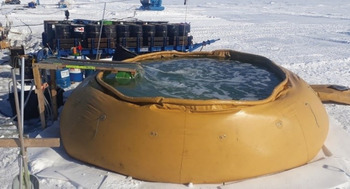
Over the 2154 m of the BEAMISH borehole, the volumetric loss of water, due to the phase change density of ice to water during the drilling process, was ~12.25 m3. Surface water must account for the loss, which was provisioned by a 30 000 L flexible, plastic-coated fabric tank or ‘flubber’ (Fig. 11) with two 10 000 L reserve tanks. All were placed on top of 1″ thick closed-cell ethafoam insulation to prevent melting into the snow surface. A floating gantry was used to manage the intake and uptake hoses over the tank edge.

Fig. 11. 30 000 L ‘flubber’ ~2/3 full. Note the floating gantry managing hoses over the tank side.
The production of water to begin the drilling process was carried out through the recirculation of seed water, from a domestic snow melter, through two pump-heater circuits to the flubber, into which snow was shovelled from a berm pushed up alongside the tank by the PistenBully shovel. This greatly reduced the effort required in snow moving and allowed the production of 10 000 L of water in 1.5 h.
Borehole pumps and umbilicals
The BEAMISH HWD utilised subsurface borehole pumps to both return water to the surface for recirculation in the drilling process and to manage water levels within the boreholes. The purpose and creation of the recirculation system are discussed in the next section.
With the drilling process requiring 140 L min−1, it was essential that this volume flow rate was returned from the subsurface borehole pumps to maintain surface water supplies. To reduce individual unit weight and the inherent risks associated with using a single large pump, two smaller pumps and supporting umbilical systems were used. Each stainless steel, submersible borehole pump, fitted with a 9.2 kW motor, was controlled from the surface by an 11 kW three-phase inverter pump controller with its own dedicated generator. Each pump was able to recover up to 115 L min−1 from 300 m depth. The pump motor had a 150 m depth rating which would potentially limit the depth of initial deployment within a water-filled borehole.
An umbilical of thermoplastic hoses and cables was used to suspend the pump at the correct depth, power the pump, return water to the surface and to supply a hot down-flow of water to the pump to minimise the likelihood of the umbilical and pump freezing.
4G10 H07RN-F power cable was used to supply power to each pump. The large conductor cross-sectional area minimises voltage drop along the length of the umbilical and provides a spare conductor in the event of breakage of an individual conductor due to mishandling under the tension of deployment and recovery.
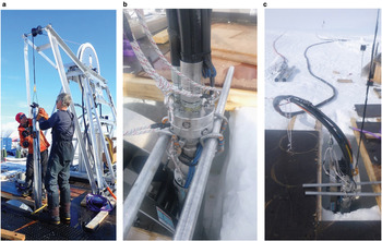
Water was returned to the surface by a 1.25″ hose with a 0.75″ hose used for the hot down-flow. During drilling, water from the flubber was pumped through a 60 kW Avtur fed heater using a 1 kW axial pump, supplying 20 L min−1 at 60–65°C through each 0.75″ hose. A spray block fitted to the top of each borehole pump (Fig. 12c) sprayed the hot water laterally within each cavity, primarily preventing the cavity from freezing up and ensuring continued connectivity between the boreholes.

Fig. 12. Deployment procedures for 9.2 kW borehole pumps and associated umbilicals. (a) Lifting 9.2 kW borehole pump into position using the truck winch and drill tower jib. (b) Spray block positioned on top of borehole pump before deployment. (c) Umbilical connected to borehole pump before deployment. Note crescent sheave in position behind.
A pressure sensor attached above each borehole pump enabled monitoring of the water level within boreholes and cavities and was the primary indicator of when the basal breakthrough occurred, leading to a change in water level. The sensor cable has a Kevlar strength member and double-shielded twisted pair conductors to minimise the effects of electrical noise from the borehole pump power cable running parallel to it.
Total weight of each umbilical and borehole pump construction was almost 1000 kg. To aid the deployment of the borehole pumps, a purpose-built jib attachment on the drill tower and a 12 v truck winch (Fig. 12a) were used to place each pump in the borehole. The umbilical was connected to the pump top using the spray block (Fig. 12b). The PistenBully, with a load cell display, was used to safely and accurately lower the umbilical and pump assembly down the borehole over a crescent, roller sheave (Fig. 12c), to the required depth. The umbilical was then secured to anchors on the surface
Two different assembly methods were used to construct each umbilical in the field. The packer umbilical construction (Figs 13a and b) aimed to facilitate field-assembly and distribute longitudinal loads to a high strength central Kevlar rope, similar to the ARA hot-water drill umbilical (Benson, Reference Benson2013). A custom rubber packer held each umbilical component in position while high strength fibreglass tape held the bundle together. Positioned every 2 m along the umbilical, each packer was required to distribute 6 kg of weight to the central Kevlar rope from which the entire construction hung.

Fig. 13. Different umbilical construction methods used in the BEAMISH HWD system. (a) Packer umbilical. (b) Packer umbilical construction. (c) Plaited umbilical.
In practice, this construction proved unsuccessful, with some elements slipping in the packers, creating loops of hose or cable, which could become frozen in the hole. In two instances, sections of umbilical did become frozen, resulting in a damaged power cable during recovery and the loss of 150 m of umbilical when it became irretrievably frozen into the ice.
The packer umbilical construction method was used with the single borehole pump deployed at Hole 1, at 150 m depth and for one of the two umbilicals deployed to 235 m at Hole 2. Previous BAS HWD projects plaited the hoses and power cable to keep them bundled together (Makinson and Anker, Reference Makinson and Anker2014). The different elongations exhibited by each member under loading would put excessive stress on the power cable, hence slack in the power cable is incorporated towards the top of the umbilical, where the hose stretch is greatest. Although used previously to a maximum depth of 125 m, plaited umbilicals 330 m long were constructed and used successfully at BEAMISH (Fig. 13c). The plaiting process required up to 10 individuals and was done in two-stages, starting from the centre and plaiting towards the ends. The 1.25″ hose was the primary strength member for hauling and supporting the borehole pump, with prior testing in the field used to determine its elongation under load.
An additional 100 m umbilical with a 5.5 kW borehole pump was used to recover water from Return Hole A (Fig. 14) and establish the first water recirculation system as per normal shallow drilling HWD operations (Makinson and Anker, Reference Makinson and Anker2014)
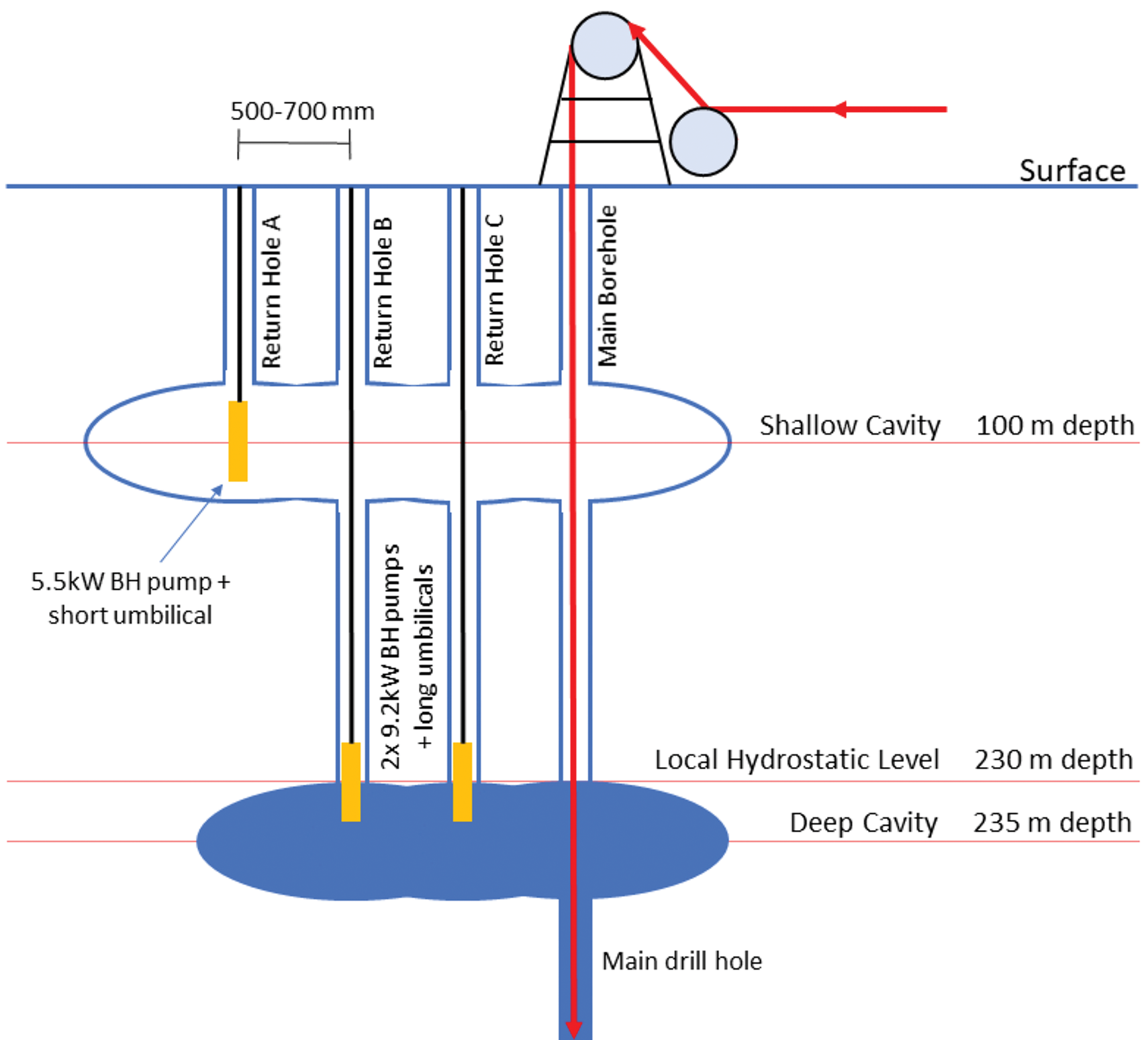
Fig. 14. Diagram detailing borehole arrangement in the cavity creation process for water recirculation and level management.
Cavity creation
The BEAMISH HWD system utilised a subsurface water recovery system to both return water to the surface for reuse in the drill system and to manage the water level within the borehole to prevent the washout of sediments on reaching the ice/sediment interface. Until the first basal breakthrough event at Hole 1, the local hydrostatic level was poorly constrained. The bounds on the water level were however known. If the ice stream were floating in sea water, the water level would be ~200 m below the surface or, if hydraulically well connected to the grounding line, the level would be ~275 m. It was, therefore, essential to have the ability to recover water from a depth of at least 275 m if the latter scenario proved to be correct, hence 330 m long umbilicals were prepared.
The essential requirements of a recirculation system are straight and vertical boreholes, with 500–700 mm separation for ease of interconnection at depth, and to prevent equipment entanglements. If holes are nonvertical, umbilical elements resting on the borehole sidewall can potentially become frozen and trapped. Such potential problems were highlighted during the SLE project, where the large borehole separation at the surface, compounded by nonvertical holes, prevented the interconnection being achieved at 300 m depth, causing the loss of the borehole pump and umbilical and resulting in the termination of drilling operations (Siegert and others, Reference Siegert, Makinson, Blake, Mowlem and Ross2014).
During the creation of the recirculation circuit, the drill system operated at 75% capacity, saving significant fuel and reducing the use of various system components. Drilling speeds were typically 1 m min−1 with all drilling to the deep cavity depth carried out using a nozzle producing a cone-shaped spray pattern with a 30° spray angle. This proved most efficient through the porous firn layer and sufficient through the more consolidated ice at greater depths.
When creating cavities, flat spray nozzles (Spraying Systems Co, Stainless Steel Deflectojet 150 SS 8686–3/8) provided efficient radial melting to more than 1 m from the hole centre. This allowed multiple boreholes to be connected to the same cavity and avoided the lengthy process of creating the cavity for each borehole. For example, a single cavity created in Return Hole C was able to provide a connection between Return Holes A, B and the Main Borehole (Fig. 14).
By creating a shallow cavity below the porous firn, water recirculation was quickly established, minimising both the loss of drill water to the firn and the water volume that later drains back into the hole and freezes on the hole wall, potentially trapping umbilicals. Seismic survey estimated firn/ice transition at 70 m depth. The shallow cavity was therefore created at 100 m depth, allowing a certain amount of temporary water storage above the cavity without it draining into the overlying firn. Creating a shallow cavity allows the establishment of a recirculation circuit, supplying water to the drill system during the drilling of the required deep cavities.
After completion of the first subglacial access hole, the water level stabilised at 230 m below the ice stream surface. Hence, in subsequent holes, the deep cavities were created at 235 m depth, as detailed in the below procedure. The holes were over drilled to 240 m depth to ensure clearance for pump deployment. With a vertical separation of 135 m between shallow and deep cavities, the borehole pumps could therefore be deployed directly to the deep cavity without exceeding the 150 m pressure rating of their motor housings.
The following steps were followed in the creation of the water recirculation circuit. Figure 14 details hole positions and cavity depths. Holes were aligned along the longitudinal axis of the tower sheave wheel, simplifying accurate relocation of the winch when moving between hole positions.
1. Creation and storage of sufficient water to establish shallow recirculation circuit (10 000 L).
2. Drill Return Hole A to 100 m (brass nozzle weight + cone spray tip) and initiate shallow cavity.
3. Deploy 5.5 kW borehole pump and short umbilical to 95 m. Recover water to surface. Enlarge cavity using pump spray block.
4. Move drill tower to Return Hole B position and drill to 100 m. Create cavity at 95 m (flat spray nozzle tip) to connect holes A and B and establish shallow recirculation circuit.
5. Continue drilling Return Hole B (brass nozzle weight + weight stack + straight nozzle tip) to 240 m. Initiate deep cavity. Return to surface
6. Move drill tower to Return Hole C position and drill to 240 m, intersecting shallow cavity. Initiate and then enlarge cavity (flat spray nozzle tip) to connect holes B and C.
7. Move drill tower to Main Borehole position and drill to 240 m intersecting shallow and deep cavities. Use camera system to confirm the connection of boreholes at a deep cavity.
8. Recover 5.5 kW pump and short umbilical.
9. Deploy 9.2 kW borehole pumps and long umbilicals to 235 m in both boreholes B and C. Enlarge deep cavity using pump spray blocks and drawdown water level.
10. Re-position tower to Main Borehole. Resume drilling from a deep cavity to ice base (brass nozzle + weight stack + straight spray tip).
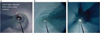
The borehole camera imagery shown in Figure 15a demonstrates the borehole is straight and vertical: the perpendicular reflection of the camera system torch, at ~120 m depth, from the water surface at 230 m depth is clearly visible. Figure 15b, from within the water column, shows three boreholes connected at ~200 m depth before water levels were drawn down. Figure 15c is from ~5 m above the main deep cavity, at 235 m depth, at hole 3. The fluting seen on the walls was created by the horizontal sprays of the pump spray blocks as the vertical position of the umbilicals varied with changing water levels. (Fig. 12c).

Fig. 15. Images from within boreholes, showing the creation of cavities connecting boreholes at depth. (a) Hole 2 – Demonstration of hole verticality. (b) Hole 2 – Interconnection of boreholes at depth. (c) Hole 3 – Just above the main cavity, showing fluting.
Instrumentation
Monitoring system
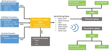
A system to monitor the primary parameters of a HWD system, developed and field-tested over the previous 5 years, was used at BEAMISH. The parameters being logged and displayed were broadly split into the drill water parameters and winching parameters as detailed in Figure 16. Winch parameters were derived from load cells and an encoder located on the sheave wheel, with panel meter display on the winch control panel. The instrumented manifold (Fig. 3) with flow, pressure and temperature sensors provided monitoring of the main drill water supply and had local panel meter displays. Pressure sensors mounted just above the borehole pumps monitored borehole water level. Having a pressure sensor with each pump provided redundancy for this critical measurement, needed for both managing borehole water level and alerting drillers when the ice base is reached.

Fig. 16. Monitoring system schematic detailing the parameters recorded and their distribution to the user.
A VM2 micro controller from Venom Control Systems Ltd., Cambridge, managed the RS485 outputs from the sensors' panel meters. It both logged data internally at 1 second intervals and redistributed it through a serial data cable to the primary laptop, and through a wireless serial string for use across the site on any secondary laptop. The primary laptop was sited at the winch control panel and utilised Grafana, an interactive visualisation web application, providing a graphical interface of real-time and past system performance (Fig. 20). The VM2 logger output either load or depth parameters to a large 6″ high, eight segment display unit, that proved invaluable during drilling and sediment coring.
Borehole camera system
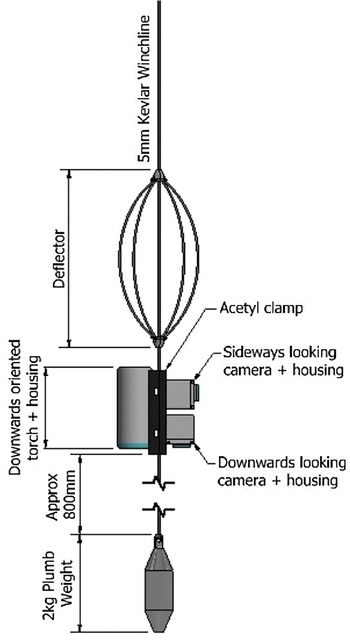
Two GoPro Hero 4 camera units with extended battery packs, housed in custom pressure casings from CamDo Solutions, USA, rated to 1400 m, were used to inspect the upper parts of the boreholes (Fig. 17). Light was provided by an LED torch powered by four 18650, 2.6 Ah batteries housed in a pressure casing rated to 1250 m. A steel deflector clamped above the assembly, prevented snagging on recovery and a steel plumb weight stabilised descent.

Fig. 17. Borehole Camera System arrangement.
The camera system was used during the construction of deep cavities, specifically to confirm that adjacent boreholes were connected to each other at depth. Imaging subsurface cavities also allowed estimation of water storage available at depth for recovery to the surface.
Borehole logging
A programmable autonomous Down Hole Instrument (DHI) package for measurement of the borehole was developed for deployment at BEAMISH (Fig. 18). Although the system could operate mounted on the drilling hose, it was used on a rope tether and deployed through the full depth of the ice stream once drilling had been completed.

Fig. 18. DHI package prepared for tethered deployment.
Three horizontal altimeters measured hole diameter, while three cameras recorded basal sediment and ice conditions throughout the borehole length. The system and the collection of data from the BEAMISH borehole is described in detail by McAfee, and others (Reference McAfee2021)
Drilling calculations
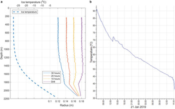
A HWD calculation script has been developed within BAS, and utilised in all previous drilling projects, to determine the drilling speed needed to provide the required hole diameter profile. It follows a simple energy-balance model which is iterated along the estimated depth of the ice column (Humphrey and Echelmeyer, Reference Humphrey and Echelmeyer1990). Primary input parameters are drill water flow and temperature, drill hose properties, an estimate of ice thickness and ice temperature, and the required hole diameter at a specific time after drilling is complete. The temperature profile within the ice column to be drilled is usually not known prior to drilling, therefore at the Rutford Ice Stream drill site the basal temperature was assumed to be at the in situ freezing point. Given an estimate of the surface accumulation rate and solving the 1-D advection-diffusion equation, the temperature profile was estimated.
Heat loss along the length of the drilling hose was calculated as part of the HWD calculation script and was verified through the installation of a temperature logger installed in the nozzle (Fig. 10) which recorded water temperature at the nozzle tip through the full drilling period of Hole 2 (Fig. 19b). This data allowed an improved estimate of the thermal conductivity properties of the main drilling hose with a thermal resistance of 0.27 W mK−1 given.

Fig. 19. Graphs showing; (a) calculated borehole diameter predictions at various periods after drill nozzle recovery. Blue dotted line shows the associated calculated temperature profile through the ice column. (b) Measured water temperature at the drill nozzle tip through the drilling period of the main borehole at Hole 2.
A hole with a nominal diameter of no less than 300 mm 10–15 h after drilling finished was required at BEAMISH to allow transit of instrumentation. A 140 L min−1 flow rate and temperatures of 85°C were assumed. The resulting plots (Fig. 19a) show the predicted hole radius immediately after drilling is complete and 10, 20 and 30 h later. The script most importantly calculates the drill speed over each 10 m section of the borehole needed to obtain the required hole diameter profile. This speed profile was followed by the drilling engineer, who adjusted the capstan winch speed accordingly. In practice, the maximum speed was limited by the fact that much of the hole does not widen immediately, leading to a tapered profile with widening taking place over several metres above the nozzle. This meant that at nozzle speeds that were too high, the hole had not widened sufficiently to allow the weight stack to pass.
Initial analysis of the hole diameter along its entire depth using the new prototype down hole instrumentation system (McAfee and others, Reference McAfee2021) suggest this instrument will be valuable in validating these predictions. In future deep drilling projects, the combination of good predictions and hole validation data will allow more efficient drilling operations, that optimise fuel usage and hole availability.
Drilling process
The BEAMISH HWD system largely followed the drilling methods used in previous BAS HWD operations (Makinson, Reference Makinson1993; Makinson and Anker, Reference Makinson and Anker2014). Below we broadly describe the processes followed across the three holes drilled at BEAMISH. Variations between holes are detailed in the hole specific sections.
Drilling of the main access borehole was at a nominal 1 m min−1 although this varied with ice depth and was defined by the drill speed profile determined by drill calculations. Throughout the drilling process, a consistent 140 L min−1 water at ~85°C was supplied.
To minimise basal washout of sediment, water levels within the borehole were lowered to below the 230 m approximate depth of the local hydrostatic pressure. By increasing the borehole pump speeds, abstraction rates exceeded flow through the drill nozzle, lowering water levels as the nozzle approached the ice base. On basal breakthrough, a rapid increase in borehole water level was observed (Fig. 21) indicating water flowing into the bottom of the borehole. At this point, forward progress of the nozzle was halted, and it was immediately recovered upwards at 1 m min−1 to prevent the water jet washing out basal sediment. The nozzle was then recovered to the surface at the maximum winch speed of 9 m min−1, taking ~4 h to transit the hole, leaving it ready for use for science.
The umbilicals and borehole pumps remained down hole and running during the science use of the access borehole. Pump speeds were reduced to match the downhole flow through the 60 kW heater system which continued to supply hot water to the spray block to minimise freezing in of the umbilical.
During science operations the drill system ran at a minimal level, allowing full operations to restart within 20 min if needed. All heaters were powered off and pumps run at 20% speed. Flubber water temperatures were monitored throughout tick over with recirculated water maintaining a temperature of ~10°C for the science operations period.
Once all operations were completed, water was removed from equipment and hoses, flushed with a 50% antifreeze water mixture and compressed air used to recover the antifreeze. Propylene glycol was used as antifreeze due to its nontoxic properties and was dyed blue to distinguish it from pure water during the flushing processes. To remove water from the 2300 m drill hose, the hose drum winch was run in reverse, ‘walking’ the water out of the hose via the central rotary coupling. In addition, by introducing 10 L of antifreeze mixture into the hose end it was possible to verify all water had been removed once it had transited through the hose. The drill hose dewatering process took ~3 h.
Drilling field season 2018/19
A comprehensive narrative of the BEAMISH field season has been given by Smith (Reference Smith2020). The BEAMISH drilling field season commenced with field party input on Rutford Ice Stream in early November 2018. A month of system assembly and testing was programmed into the season schedule. In total, three subglacial access holes were successfully drilled, with the second planned hole at Site 2 not attempted due to time limitations. The basic figures for each hole are detailed in Table 3.
Table 3. Hole drilling operation figures across BEAMISH field season

a Only a single umbilical and shallow 150 m cavity used.
b Slow recovery of the nozzle to the surface.
Predicted fuel usage to drill each hole: 7750 L Avtur and 2250 L petrol.
The BEAMISH system was operated with a maximum team size of 12 individuals. With hole operation periods of up to 6 days, a shift pattern ensured at least three individuals were always available to monitor the operation of the drill.
Hole 1 operations
The hydrostatic water level was not known prior to drilling Hole 1 so no attempt at managing water levels was made. Instead, a single borehole pump, deployed to 150 m depth, proved sufficient to return the 140 L min−1 of water required to maintain surface stocks. On basal breakthrough, water levels dropped below the pump, requiring adequate surface water storage to ensure full system operation during recovery of the drill nozzle to the surface.
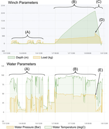
A record of the primary drilling parameters was maintained throughout the full drilling period of Hole 1, with a live display on the Grafana dashboard, as shown in Figure 20, displaying all data collected over the 4 days of operation. The dashboard graphically displays time series data and real-time values of drill system parameters. Period (A) covers the time spent creating the recirculation cavities with the period (B) showing the 30 h taken to drill the main borehole. Period (C) shows the rapid recovery of the drill nozzle to the surface following successful basal breakthrough.

Fig. 20. Winch and water parameter displays of Grafana monitoring system, showing the full operating period of hole 1. Annotations identify critical moments/periods in the operations. (A) Circulation cavity creation. (B) Drilling main borehole. (C) Nozzle recovery to surface. (D) Large load increase on ice base breakthrough. (E) Water pressure drop on breakthrough.
With the high-water level in the borehole at the moment of basal breakthrough, water levels dropped an initial 30 m in just 1 minute. This caused a significant load increase on the drill hose (Fig. 20D) as water flushed past the nozzle and the supporting buoyancy of the water within the borehole was reduced. The water drop was also identified through a significant drop in drill hose water pressure (Fig. 20E) as the relative head of drill water increased. On completion of drilling and attempted recovery of the umbilical, the pump with the 150 m packer umbilical was found to have frozen into the hole and was irretrievable.
Hole 2 operations
Hole 2 was sited 10 m downstream of Hole 1 at BEAMISH site 1. The drill system remained in position with only the winch tower and hose drum winch moving from their Hole 1 position.
The successful basal connection at Hole 1 established the local hydrostatic level at ~230 m below the ice stream surface. Two umbilicals were constructed for deployment to 235 m depth, one with the packer construction method the other with the plaited construction method.
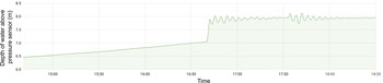
With both pumps below the hydrostatic depth, borehole water levels were successfully managed through the drilling process. On basal breakthrough, water levels increased by ~1 m (Fig. 21), causing minimal disturbance to the in situ sediments. Successful use of a sediment corer verified the favourable condition of basal sediments following access hole creation. Sediment was also collected in the nozzle sediment cups (Fig. 22) and most likely of englacial origin.

Fig. 21. Plot of water level within Hole 2 on 20 January 2019 showing an increase in water depth signifying the moment of basal breakthrough and the avoidance of washout of basal sediments.

Fig. 22. Nozzle sediment cup with collected sediment, shown immediately after the first return of nozzle to surface at Hole 2.
Hole 3 operations
Hole 3 was drilled at site 2, ~2 km downstream of Holes 1 and 2 at site 1 and required the relocation of the entire drilling system. Seismic measurements suggested little difference in ice thickness at site 2 from site 1, so the hydrostatic level was estimated as 230 m with a cavity created at 235 m. Two plaited umbilicals were deployed to 235 m.
During drilling, and on approaching the expected basal depth of the ice, a significant drop in load measured on the hose was noted (Fig. 23B) and forward drilling progress proved impossible. The nozzle was returned to the surface and the spray tip swapped for a smaller straight jet, with the intention to force water through the obstruction. An extended attempt to drill through the obstruction (Fig. 23C) was unsuccessful with the borehole water level remaining unchanged, indicating no hydraulic continuity with the ice base. Subsequent nozzle recovery to the surface was carried out at a slower speed of 5.2 m min−1, primarily to give operators an opportunity for rest but also to enlarge the middle depth sections of the borehole. This slow recovery led to the significant increase in fuel usage at Hole 3 when compared to Holes 1 and 2 (Table 3).

Fig. 23. Plot of monitoring system winch parameters at Hole 3, showing drilling operations affected by a basal obstruction. (A) Drilling main borehole. (B) Interaction with basal obstruction with associated load reduction. (C) Second attempt at drilling past the basal obstruction and repeated load reduction. (D) Slow recovery of the nozzle to surface. (E) Deployments of DHI package. (F) Attempt at sediment coring.
Sediment sampling was attempted in the borehole (Fig. 23F) using a new hammer arrangement (Makinson, Reference Makinson2021). While the new mechanism operated successfully, no indication of penetration was noted during the hammering process and, following recovery, damage to the corers' cutter head suggested that a boulder of some description was the probable cause of the obstruction (Smith, Reference Smith2020). Two deployments of the DHI package were carried out to the basal obstruction (Fig. 23E) with recovered imagery from the camera system indicating turbid water at the base. No visible evidence of the obstruction was recovered due to the water conditions.
By pumping water down through both umbilicals during the DHI and sediment corer deployment periods, water levels within the borehole were raised 72 m above the predicted hydrostatic level. Approximately 34 h after first reaching the obstruction, a steady drop in the water level of 69 m occurred over 30 min, signifying a basal breakthrough. The proposed mechanisms of the breakthrough are discussed in Smith (Reference Smith2020).
Conclusions
The new BAS BEAMISH hot-water drill system was used to successfully create three subglacial access holes through up to 2154 m of ice to the base of the Rutford Ice Stream, Antarctica. These are the deepest hot water drilled subglacial access holes so far created and demonstrate drilling methods and procedures for the safe, reliable and repeatable creation of cavities by connecting parallel boreholes at depth.
The access holes created allowed the recovery of sediment samples from the ice stream using samplers on the drill nozzle or from the bed using a simple sediment corer (Makinson, Reference Makinson2021) as well as the in-ice installation of a range of monitoring instrumentation to aid in describing ice-sheet dynamics (Smith, Reference Smith2020). Disturbance of the basal sediment was also minimised by the ability to manage the borehole water level at breakthrough.
A drill monitoring system proved invaluable in managing and reviewing drill performance. Integrating this with data recovered from trialled downhole logging instrumentation will further increase confidence in temporal borehole development and efficiency gains in any future deep drilling operations.
The BEAMISH hot-water drill system and drilling procedures confirm that deep subglacial access using hot water is viable and repeatable at depths of over 2000 m. Building on these successes, future projects with the goal of accessing deep subglacial lake targets can progress this drilling methodology. Consequently, major components and the processes used within the BEAMISH HWD are being integrated into a new clean access hot-water drill system being developed with the goal of accessing Subglacial Lake CECs in West Antarctica (Makinson, Reference Makinson2021).
Acknowledgements
This technical development was supported by the UK Natural Environment Research Council under AFI grant NE/G014159/1, Basal Conditions on Rutford Ice Stream: Bed Access, Monitoring, and Ice Sheet History (BEAMISH) and NERC grant NE/R016038/1, National Capability – Polar Expertise Supporting UK Research.


 Open access