


1. Introduction
Autonomous interception of an aerial intruder using autonomous UAVs is an important problem for the defence of a strategic area as it might not be possible to deploy a costly and complex air-defence system. However, due to payload restrictions on UAVs, it is difficult to include traditional seeker/ radar sensors for the interception of a target, and the feasibility of standard guidance algorithms is limited. Also, the lethal radius of the attached warhead to the interceptor UAV will be limited due to its payload carrying capacity constraints. Target interception using visual information is a viable alternative solution as it could be performed with a lightweight and cheaper camera module.
Vision-based aerial interception using UAVs in an outdoor environment is a challenging task due to uncertainty involved in visual information due to limitations in the field of view, pixel noise, and occlusions associated with the camera and the delay associated with processing visual information due to limitation in computational power. Also, vision-based strategies that use estimated target depths are likely to result in large miss distances in the terminal phase of interception as estimation of target depth using a camera will have high uncertainty in the outdoor environment. In this paper, we propose a guidance algorithm that does not use camera-based depth information and yet performs effectively the task of capturing the target.
In the literature, interception of a target using visual information is achieved by generating acceleration command using position-based visual servoing (PBVS) techniques [Reference Chaumette and Hutchinson1, Reference Xu, Liang, Li and Xu2, Reference Ding, Guo, Liu and Luo3, Reference Beul, Bultmann, Rochow, Rosu, Schleich, Splietker and Behnke4, Reference Sharma, Shukla, Behera and Subramanian5, Reference Ghasemi, Parivash and Ebrahimian6], image-based visual servoing (IBVS) techniques [Reference Mebarki and Lippiello7, Reference Kim, Seo, Choi and Kim8, Reference Suarez, Soria, Heredia, Arrue and Ollero9] or a control strategy based on target dynamics on the image plane [Reference Lin, Yang, Cheng and Chen10, Reference Yuan Tian and Ren11, Reference Freda and Oriolo12, Reference Shareef, Just, Teichrieb and Trächtler13]. In the case of PBVS techniques, the control command is generated based on the reconstruction of the target pose in 3D, whereas in IBVS techniques, the control command is generated based on the desired location of the target pixel involving the interaction matrix. In both techniques, the target depth information is required. In the last approach, the control strategy is developed based on the error between the desired target location and the current target location on the image plane without using target depth information. The desired location of the target pixel is obtained through prediction techniques [Reference Parnichkun and Thalagoda14, Reference Dong and Zhu15, Reference Su and Shen16] or using standard guidance algorithms [Reference Mehta, Ton, Kan and Curtis17]. A good survey about reaching and grasping of objects with a manipulator using visual information is provided in ref. [Reference Marwan, Chua and Kwek18].
In ref. [Reference Freda and Oriolo12], interception of a moving target with a non-holonomic robot using pan-tilt is presented with a two-level controller structure, where the camera is controlled at a lower level to keep the target at the centre of the image plane, and the robot is driven using the relative position information of the target from the image plane. In some cases, target interception based on path planning strategy is used after the prediction of the target motion [Reference Zhang, Wang and Fang19, Reference García, Viguria, Heredia and Ollero20]. An adaptive dynamic path planning strategy, based on a modified Dubin algorithm, is used for interception of a moving target [Reference Triharminto, Prabuwono, Adji and Setiawan21]. A combination of PBVS and IBVS methods is used for aerial grasping of static objects using a manipulator attached to quadrotor [Reference Lippiello, Cacace, Santamaria-Navarro, Andrade-Cetto, Trujillo, Esteves and Viguria22]. Visual grasping for microair vehicle systems equipped with a monocular camera is reported in ref. [Reference Thomas, Loianno, Sreenath and Kumar23], where trajectory planning is performed directly in the image plane using the property that the system is differential flat, and image coordinates are the flat outputs. In this case, the yaw and lateral motion of the UAV is controlled by the position information Vicon system. Contact operation of an emergency switch using an aerial manipulator is reported in ref. [Reference Meng, He, Li, Gu, Yang, Yan and Han24], where an interception algorithm is formulated after target position estimation using a motion capture system. In ref. [Reference Seo, Kim and Kim25], a vision-based strategy for aerial grasping of a static cylindrical object is formulated using the stochastic model predictive approach.
Exiting strategies on the aerial interception using visual information are based on the prediction of target pixel or after estimation of target pose in 3D. In ref. [Reference Strydom, Thurrowgood, Denuelle and Srinivasan26], interception of moving target is formulated after estimation of target relative position and velocity from stereo images. Interception by a missile using information from a monocular camera is developed using a control strategy based on the error between the desired target coordinates in the image plane, obtained using a guidance algorithm, and the actual target coordinates, where the predicted target coordinates are obtained using a guidance algorithm. In ref. [Reference Yuan Tian and Ren11], the guidance strategy is formulated as an adaptive control problem using the line-of-sight (LOS) angular rate and target-image information using an imaging seeker, and target acceleration is considered as a time-varying bounded external disturbance. However, no field test is performed in both cases. In ref. [Reference Yoon, Kim and Kim27], a stationary vision-based net recovery of fixed-wing UAV is proposed with pursuit guidance and adaptive back-stepping controller; however, no simulation or field test is reported based on the visual information. Here, it is assumed that line-of-sight information is available from visual information. In another approach, the interception algorithm of a moving target is developed using a PD-based controller after estimation of target position, velocity, and acceleration [Reference Tao, Song, Lin, Jin and Li28].
The problem statement in the present paper is motivated by Challenge 1 of the Mohamed Bin Zayed International Robotics Challenge (MBZIRC-2020) [29]. The challenge involves grabbing a ball of diameter 100 mm hanging from a manoeuvring drone moving in a variable figure-of-eight trajectory in an unknown environment. Algorithms based on target position estimation are reported for interception in this scenario [Reference Barisic, Petric and Bogdan30, Reference Zhao, Shi, Anzai, Takuzumi, Toshiya, Kita, Naoki and Kei31, Reference Cascarano, Milazzo, Vannin, Andrea and Stefano32]. In refs. [Reference Barisic, Petric and Bogdan30, Reference Zhao, Shi, Anzai, Takuzumi, Toshiya, Kita, Naoki and Kei31], velocity command is generated proportional to tracking error between the current position of the interceptor and desired position, where the desired position is obtained after estimation of the target’s 3D position. In ref. [Reference Cascarano, Milazzo, Vannin, Andrea and Stefano32], the forward velocity command is generated proportional to the target distance, and lateral velocities are generated based on the error in the lateral alignment. Here, the yaw command is also provided based on the errors in the $x$
location of pixel coordinates in the image plane.
$x$
location of pixel coordinates in the image plane.
The interception strategy of a manoeuvring target which is based on pixel error, target depth measurement, and predicted location of the target pixel can have considerable miss distance due to uncertainty involved in the estimation of the target pixel location and will not be useful for those applications where the miss distance needs to be very small due to the capability of the mechanism/payload attached to interceptors. In the case of interception scenario using standard guidance algorithms such as Proportional Navigation (PN), Pure Pursuit (PP) and Augmented Proportional Navigation (APN), lateral acceleration is applied to the interceptor, is proportional to the LOS rate [Reference Zarchan33], [Reference Siouris34]; however, the LOS rate information from the image information can have huge uncertainty due to high pixel noise and delay involved in processing the information. Therefore, standard guidance algorithms cannot be applied directly using visual information. Existing approaches to vision-based interception are based on target pose estimation or error in the desired target pixel [Reference Yuan Tian and Ren11, Reference Strydom, Thurrowgood, Denuelle and Srinivasan26, Reference Yoon, Kim and Kim27, Reference Tao, Song, Lin, Jin and Li28, Reference Barisic, Petric and Bogdan30, Reference Zhao, Shi, Anzai, Takuzumi, Toshiya, Kita, Naoki and Kei31, Reference Cascarano, Milazzo, Vannin, Andrea and Stefano32]; therefore, their efficiency will be limited in an unstructured outdoor environment. Also, interception strategies based on stereo vision will require higher computational requirements and payload budget.
In this paper, a vision-based guidance algorithm is developed for interception of a manoeuvring target using the information from a monocular camera. The guidance algorithm is developed for the interception of a target ball with a camera centre fixed to a side-wise extended manipulator attached to the UAV (see Fig. 1). The proposed guidance strategy generates a command based on the target pixel’s alignment to the camera centre without using the pixel error or target depth information. It computes the desired velocity at the centre of gravity (CG) of the UAV such that the camera centre moves along the line joining the target pixel location in the image plane and the camera centre. The guidance algorithm is analysed for the interception of a manoeuvring target in 3D space using the concept of pursuit guidance using information from a monocular camera. The possible trajectories of the components of relative velocity between the target and interceptor are analysed. In the case where the speed of the interceptor is higher than that of the target, it is shown that by moving the camera centre towards the target pixel location, the projected location of the target in the image plane moves towards the centre of the image plane, leading to an interception. The proposed guidance algorithm is initially validated through simulation in a Gazebo environment and successfully tested in an outdoor environment for interception of a target ball using a hexacopter as an interceptor.

Figure 1. Target-interceptor engagement geometry.
Existing vision-based strategies are based on the PBVS or IBVS or based on the error in the desired target position in the image plane. Our approach does not consider the estimated target depth or the error in target pixel as they have huge uncertainty in the outdoor environment. Our approach is based on the orientation of the target to reduce the effect of pixel noise on the efficiency of interception. As the problem statement in the paper is motivated by Challenge 1 of MBZIRC-2020, many other groups also worked in parallel to solve a similar problem. In a later section, we will briefly discuss the other approaches vis-a-vis the approach followed in this paper to highlight the novelty of our work. The main contributions of our paper are the following:
-
1. Design and experimental validation of guidance algorithm only using only target orientation in the image plane for interception of manoeuvring target in 3D space.
-
2. Analysis of the vision-based 3D guidance algorithm in relative velocity space of target and interceptor.
The paper is organised as follows: Section 2 gives the design of the guidance algorithm. Analysis of the guidance algorithm is performed in Section 3 while Section 4 presents the simulation results performed in Gazebo environment. Section 5 describes the hardware used and experimental results. Section 6 concludes the paper.
2. Guidance algorithm
For the work presented in this paper, it is assumed that the target is in the field of view of the interceptor drone at the start of the interception. Although for the original problem, it was necessary to also design a search phase for the initial part where the capturing UAV searches for the target and identifies it; this search phase is not in the scope of the present paper. In general, the guidance algorithm is developed to command the lateral acceleration at the CG of the vehicle based on the relative geometry between the target and the interceptor. In this paper, the vision-based guidance algorithm is designed using the relative geometry between the camera centre and the target point, and this also helps to keep the target in the field of view of the camera. Since the camera is not attached to the CG of the interceptor, so, the desired command is appropriately transformed from the camera centre to the vehicle CG.
A typical engagement geometry is shown in Fig. 1, where the projection of target object ( $T_{x}$
,
$T_{x}$
, $T_{y}$
,
$T_{y}$
, $T_{z}$
) in the image plane is O and its coordinates in the camera frame are (
$T_{z}$
) in the image plane is O and its coordinates in the camera frame are ( $x_{T}$
,
$x_{T}$
, $y_{T}$
,
$y_{T}$
, $f$
), where
$f$
), where $f$
is the focal length of the camera, and
$f$
is the focal length of the camera, and $X_{c}$
,
$X_{c}$
, $Y_{c}$
,
$Y_{c}$
, $Z_{c}$
are the different axes of the camera frame. Units of the variables are considered in SI units, such as position in metres, velocity in m/s, and acceleration in m/s
$Z_{c}$
are the different axes of the camera frame. Units of the variables are considered in SI units, such as position in metres, velocity in m/s, and acceleration in m/s $^{2}$
. Considering a perspective projection model, the projection of the target point in the image plane can be expressed as
$^{2}$
. Considering a perspective projection model, the projection of the target point in the image plane can be expressed as
 \begin{align} x_{T}=\frac{T_{x} \,f}{T_{z}}; \quad y_{T}=\frac{T_{y} f}{T_{z}} \end{align}
The proposed guidance algorithm has two components: the primary component generates the desired velocity for the interceptor $(V_{\text{des}})$
and the secondary component generates the desired yaw rate
$(V_{\text{des}})$
and the secondary component generates the desired yaw rate $(r_{\text{des}})$
. The commanded desired velocity of the interceptor from the guidance block is the main command responsible for the interception, and the commanded yaw rate is used to keep the target in the field of view of the camera attached to the interceptor. The primary guidance is generated similar to pursuit guidance, where the interceptor moves directly towards the target. The desired velocity
$(r_{\text{des}})$
. The commanded desired velocity of the interceptor from the guidance block is the main command responsible for the interception, and the commanded yaw rate is used to keep the target in the field of view of the camera attached to the interceptor. The primary guidance is generated similar to pursuit guidance, where the interceptor moves directly towards the target. The desired velocity $(V_{\text{des}})$
at the CG of the interceptor is commanded such that the resultant velocity
$(V_{\text{des}})$
at the CG of the interceptor is commanded such that the resultant velocity $(V_{Ic})$
at the camera centre
$(V_{Ic})$
at the camera centre $(I)$
is aligned towards the line joining the target pixel point (O) and the camera centre. The unit vector (
$(I)$
is aligned towards the line joining the target pixel point (O) and the camera centre. The unit vector ( $T_{cx}$
,
$T_{cx}$
, $T_{cy}$
,
$T_{cy}$
, $T_{cz}$
) along the line between the camera centre and the target pixel can be obtained as
$T_{cz}$
) along the line between the camera centre and the target pixel can be obtained as
 \begin{equation} T_{cx}= \frac{x_{T}}{\sqrt{x_{T}^{2}+y_{T}^{2}+f^{2} }} ; \quad T_{cy}=\frac{y_{T}}{\sqrt{x_{T}^{2}+y_{T}^{2}+f^{2} }}; \quad T_{cz}= \frac{f}{\sqrt{x_{T}^{2}+y_{T}^{2}+f^{2} }} \end{equation}
Therefore, if the magnitude of the interceptor velocity is $V_{I}$
, then the velocity of the interceptor in the camera frame is
$V_{I}$
, then the velocity of the interceptor in the camera frame is
 \begin{equation} v_{x}= V_{I} T_{cx}; \quad v_{y}=V_{I} T_{cy}; \quad v_{z}= V_{I} T_{cz} \end{equation}
The magnitude of the interceptor velocity ( $V_I$
) can be set as the maximum allowable velocity of the interceptor. Finally, the desired velocity of the interceptor in the camera frame (
$V_I$
) can be set as the maximum allowable velocity of the interceptor. Finally, the desired velocity of the interceptor in the camera frame ( $V_{Ic}$
in Fig. 1) is transformed using the appropriate rotation matrix
$V_{Ic}$
in Fig. 1) is transformed using the appropriate rotation matrix $(R_{c2i})$
to represent it in the interceptor’s vehicle frame (
$(R_{c2i})$
to represent it in the interceptor’s vehicle frame ( $V_{\text{des}}$
) and then fed to the controller block for generation of motor PWM. The desired velocity
$V_{\text{des}}$
) and then fed to the controller block for generation of motor PWM. The desired velocity $V_{\text{des}}$
in the vehicle frame is obtained as
$V_{\text{des}}$
in the vehicle frame is obtained as
 \begin{equation} V_{\text{des}}=R_{c2i} \begin{bmatrix} v_{x}, v_{y}, v_{z} \end{bmatrix}^T \end{equation}
The components of the $V_{\text{des}}$
along the axes of the vehicle frame are
$V_{\text{des}}$
along the axes of the vehicle frame are $V_{x}^{d}$
,
$V_{x}^{d}$
, $V_{y}^{d}$
, and
$V_{y}^{d}$
, and $V_{z}^{d}$
. Apart from the primary velocity commands, the interceptor is also subjected to a yaw rate to aid in keeping the target in the field of view of the camera. A PD-based controller is used to calculate the desired yaw rate based on the error in desired yaw and actual yaw. The desired yaw
$V_{z}^{d}$
. Apart from the primary velocity commands, the interceptor is also subjected to a yaw rate to aid in keeping the target in the field of view of the camera. A PD-based controller is used to calculate the desired yaw rate based on the error in desired yaw and actual yaw. The desired yaw $(\psi _{\text{des}})$
is calculated based on the desired velocity command in
$(\psi _{\text{des}})$
is calculated based on the desired velocity command in $x$
and
$x$
and $y$
direction of the vehicle frame from the primary guidance block.
$y$
direction of the vehicle frame from the primary guidance block.
 \begin{equation} \psi _{\text{des}}=-\!\arctan \!\left(V_{y}^{d}/V_{x}^{d}\right) \end{equation}
The error $(e_{\psi })$
in desired yaw and actual yaw
$(e_{\psi })$
in desired yaw and actual yaw $(\psi )$
is obtained as.
$(\psi )$
is obtained as.
 \begin{equation} e_{\psi } = \psi _{\text{des}}-\psi. \end{equation}
Then, the desired yaw rate $(r_{\text{des}})$
is obtained using a PD-based controller, and the PD gains (
$(r_{\text{des}})$
is obtained using a PD-based controller, and the PD gains ( $k_{p\psi }$
,
$k_{p\psi }$
, $k_{d\psi }$
) are tuned after observing the vehicle responses in the yaw plane.
$k_{d\psi }$
) are tuned after observing the vehicle responses in the yaw plane.
 \begin{equation} r_{\text{des}}=k_{p\psi } e_{\psi } +k_{d\psi } (d e_{\psi }/dt). \end{equation}
The derivative component of the PD controller is used to improve the settling time and reduce the overshoot while tracking the desired yaw. The secondary component ( $r_{\text{des}}$
) of the guidance algorithm depends on the desired yaw and the actual yaw. The desired yaw is calculated from the desired velocity command, and the actual yaw is calculated from the IMU. So, the error in the estimation of the target pixel will affect the error in yaw, but not in a huge amount. Thus, the proposed derivative term will not be significantly affected by the pixel noise; however, it will help in keeping the target in the field of view of the camera. Also, this secondary component serves only to improve the efficiency of the algorithm, and the primary component is still the main guidance command for interception. Therefore, the effect of noise in the target pixel has less effect on the efficiency of the proposed algorithm compared to a guidance strategy directly based on estimated position and velocity.
$r_{\text{des}}$
) of the guidance algorithm depends on the desired yaw and the actual yaw. The desired yaw is calculated from the desired velocity command, and the actual yaw is calculated from the IMU. So, the error in the estimation of the target pixel will affect the error in yaw, but not in a huge amount. Thus, the proposed derivative term will not be significantly affected by the pixel noise; however, it will help in keeping the target in the field of view of the camera. Also, this secondary component serves only to improve the efficiency of the algorithm, and the primary component is still the main guidance command for interception. Therefore, the effect of noise in the target pixel has less effect on the efficiency of the proposed algorithm compared to a guidance strategy directly based on estimated position and velocity.
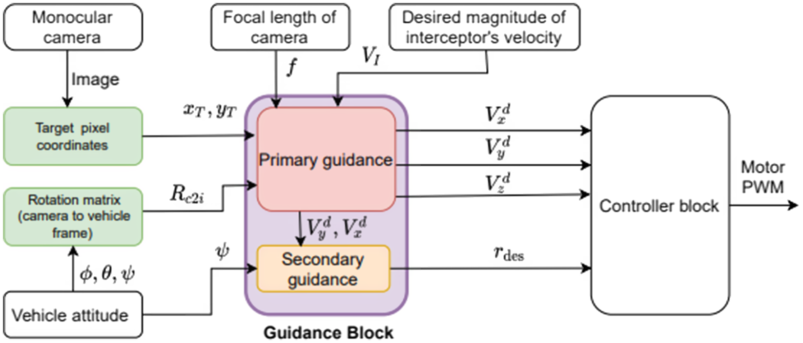
Figure 2. Guidance and control architecture.
A detailed block diagram of guidance and control architecture is shown in Fig. 2. As shown in the figure, the input to the primary guidance block is the focal length ( $\,f$
), target pixel coordinates (
$\,f$
), target pixel coordinates ( $x_{T}$
,
$x_{T}$
, $y_T$
), rotation matrix from camera to vehicle frame
$y_T$
), rotation matrix from camera to vehicle frame $(R_{c2i})$
, and desired magnitude of the interceptor’s velocity
$(R_{c2i})$
, and desired magnitude of the interceptor’s velocity $(V_{I})$
. Although the interceptor’s roll and pitch angle is not required in the basic guidance command computation, these are required for frame transformations. It is to be noted that the pixel location of the target will be affected by the interceptor’s roll and pitch angle. Similarly, the input to the secondary guidance is desired velocity in
$(V_{I})$
. Although the interceptor’s roll and pitch angle is not required in the basic guidance command computation, these are required for frame transformations. It is to be noted that the pixel location of the target will be affected by the interceptor’s roll and pitch angle. Similarly, the input to the secondary guidance is desired velocity in $x$
and
$x$
and $y$
direction of the vehicle frame and yaw
$y$
direction of the vehicle frame and yaw $(\psi )$
. Clearly, the guidance algorithm does not depend on the target velocity or depth/distance from the camera. In a realistic scenario, the controller will be affected by the modelling uncertainties and external disturbances. To address the effect of these factors on the controller, an advanced robust adaptive controller can be used to handle modelling uncertainties/ external disturbances. We assumed that the controller block of the UAV is able to track the desired command. Considering that guidance design and analysis are the main focus of our work, we have not described in detail the controller architecture of the UAV used in experiments. The guidance architecture is independent of the controller architecture, so it is applicable for any UAV as long as its controller is able to track the command with reasonable tracking performance.
$(\psi )$
. Clearly, the guidance algorithm does not depend on the target velocity or depth/distance from the camera. In a realistic scenario, the controller will be affected by the modelling uncertainties and external disturbances. To address the effect of these factors on the controller, an advanced robust adaptive controller can be used to handle modelling uncertainties/ external disturbances. We assumed that the controller block of the UAV is able to track the desired command. Considering that guidance design and analysis are the main focus of our work, we have not described in detail the controller architecture of the UAV used in experiments. The guidance architecture is independent of the controller architecture, so it is applicable for any UAV as long as its controller is able to track the command with reasonable tracking performance.
3. Analysis of guidance algorithm
In this section, the trajectories of the component of the relative velocities and the target pixel in the image plane during the engagement is analysed. The analysis of relative velocity space in 3D for collision avoidance is reported in ref. [Reference Chakravarthy and Ghose35]. Here, this analysis is extended to visual interception.
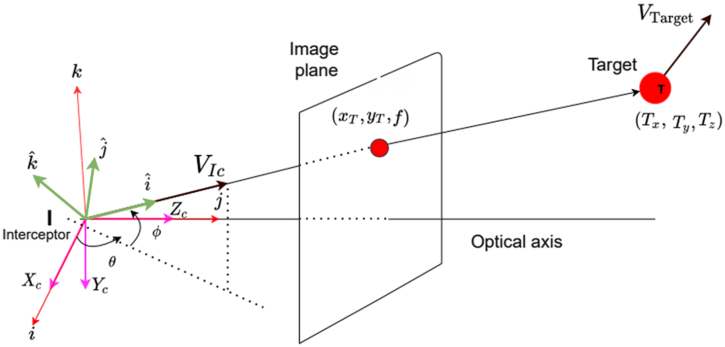
Figure 3. Engagement scenario in new frame.
As shown in Fig. 3, we define a new coordinate frame whose axes are $i$
,
$i$
, $j$
, and
$j$
, and $k$
to define the azimuth and elevation angle in line with standard literature. Elevation of line/vector is defined as the angle of a line/vector with
$k$
to define the azimuth and elevation angle in line with standard literature. Elevation of line/vector is defined as the angle of a line/vector with $i$
-
$i$
- $j$
plane, and azimuth is the angle with the
$j$
plane, and azimuth is the angle with the $i$
axis and the projection of the line/vector on the
$i$
axis and the projection of the line/vector on the $i$
-
$i$
- $j$
plane. Line TI is defined by the azimuth angle
$j$
plane. Line TI is defined by the azimuth angle $\theta$
and elevation angle
$\theta$
and elevation angle $\phi$
. The corresponding pair of angles for the target velocity (
$\phi$
. The corresponding pair of angles for the target velocity ( $V_{T}$
) is
$V_{T}$
) is $\theta _{T}$
and
$\theta _{T}$
and $\phi _{T}$
, that is,
$\phi _{T}$
, that is, $\theta _{T}$
and
$\theta _{T}$
and $\phi _{T}$
are the azimuth and elevation of the target velocity vector (
$\phi _{T}$
are the azimuth and elevation of the target velocity vector ( $V_{T}$
). Let the component of the relative velocity along the LOS between the target and the interceptor, that is, along with the line TI, be
$V_{T}$
). Let the component of the relative velocity along the LOS between the target and the interceptor, that is, along with the line TI, be $V_{r}$
and the components normal to the LOS be
$V_{r}$
and the components normal to the LOS be $V_{\theta }$
and
$V_{\theta }$
and $V_{\phi }$
. As shown in Fig. 3, let us rotate the frame
$V_{\phi }$
. As shown in Fig. 3, let us rotate the frame $i$
-
$i$
- $j$
-
$j$
- $k$
by
$k$
by $\theta$
about the
$\theta$
about the $k$
axis and then rotate the resultant frame by
$k$
axis and then rotate the resultant frame by $\phi$
about the new
$\phi$
about the new $j$
axis. Let the final resultant frame after these two rotations are
$j$
axis. Let the final resultant frame after these two rotations are $\hat{i}$
-
$\hat{i}$
- $\hat{j}$
-
$\hat{j}$
- $\hat{k}$
. Then, component of the relative velocity between the target and the interceptor along the
$\hat{k}$
. Then, component of the relative velocity between the target and the interceptor along the $\hat{i}$
,
$\hat{i}$
, $\hat{j}$
, and
$\hat{j}$
, and $\hat{k}$
axis is
$\hat{k}$
axis is $V_{r}$
,
$V_{r}$
, $V_{\theta }$
and
$V_{\theta }$
and $V_{\phi }$
, respectively. Let the distance between the camera centre and the target centre be
$V_{\phi }$
, respectively. Let the distance between the camera centre and the target centre be $R$
. The value of
$R$
. The value of $R$
is the same as
$R$
is the same as $T_{z}$
, and the symbol
$T_{z}$
, and the symbol $R$
is used to follow the same convention as standard guidance literature. Then,
$R$
is used to follow the same convention as standard guidance literature. Then, $V_{r}$
,
$V_{r}$
, $V_{\theta }$
and
$V_{\theta }$
and $V_{\phi }$
can be written as
$V_{\phi }$
can be written as
 \begin{align} V_{r}= \dot{R}; \quad V_{\theta } = R \dot{\theta } \cos \phi ; \quad V_{\phi }=R \dot{\phi } \end{align}
The velocity of the target ( $V_{\text{Target}}$
) can be expressed as
$V_{\text{Target}}$
) can be expressed as
 \begin{equation} V_{\text{Target}}=V_{T}(\!\cos \phi _{T} \cos \theta _{T}\: i + \cos \phi _{T} \sin \theta _{T}\: j +\sin \phi _{T} \: k) \end{equation}
where $V_{T}$
is the magnitude of the target velocity. The velocity of the interceptor (at the camera centre) is
$V_{T}$
is the magnitude of the target velocity. The velocity of the interceptor (at the camera centre) is
 \begin{equation} V_{Ic}=V_{I}(\!\cos \phi \cos \theta \: i + \cos \phi \sin \theta \: j +\sin \phi \: k) \end{equation}
The component of the target velocity along the LOS ( $V_{rT}$
) and perpendicular to LOS (
$V_{rT}$
) and perpendicular to LOS ( $V_{\theta T}$
,
$V_{\theta T}$
, $V_{\phi T}$
) is given by
$V_{\phi T}$
) is given by
 \begin{equation} \left(\begin{array}{c} V_{rT}\\ \\[-9pt]V_{\theta T} \\ \\[-9pt]V_{\phi T} \end{array}\right) = \left(\begin{array}{c@{\quad}c@{\quad}c} \cos \phi & 0 & \sin \phi \\ \\[-9pt]0 & 1 & 0 \\ \\[-9pt]-\!\sin \phi & 0 & \cos \phi \end{array}\right) \left(\begin{array}{c@{\quad}c@{\quad}c} \cos \theta & \sin \theta & 0 \\ \\[-9pt]-\!\sin \theta & \cos \theta & 0 \\ \\[-9pt]0 & 0 & 1 \end{array}\right) V_{\text{Target}} \end{equation}
After simplification, we get,
 \begin{equation} V_{rT}= V_{T} (\!\cos \phi \cos \theta \cos \phi _{T} \cos \theta _{T} + \cos \phi \sin \theta \cos \phi _{T} \sin \theta _{T} + \sin \phi \sin \phi _{T}) \end{equation}
 \begin{equation} V_{\theta T} = V_{T}(\!-\!\sin \theta \cos \phi _{T} \cos \theta _{T} + \cos \theta \cos \phi _{T} \sin \theta _{T} ) \end{equation}
 \begin{equation} V_{\phi T}= V_{T}(\!-\!\sin \phi \cos \theta \cos \phi _{T} \cos \theta _{T} -\sin \phi \sin \theta \cos \phi _{T} \sin \theta _{T}+ \cos \phi \sin \phi _{T}) \end{equation}
Then, the component of relative velocity between the target and the interceptor can be written as,
 \begin{equation} V_{r} = V_{T} (\!\cos \phi \cos \theta \cos \phi _{T} \cos \theta _{T} + \cos \phi \sin \theta \cos \phi _{T} \sin \theta _{T} + \sin \phi \sin \phi _{T}) -V_{I} \end{equation}
 \begin{equation} V_{\theta }=V_{T}(\!-\!\sin \theta \cos \phi _{T} \cos \theta _{T} + \cos \theta \cos \phi _{T} \sin \theta _{T} ) \end{equation}
 \begin{equation} V_{\phi }= V_{T}(\!-\!\sin \phi \cos \theta \cos \phi _{T} \cos \theta _{T} -\sin \phi \sin \theta \cos \phi _{T} \sin \theta _{T}+ \cos \phi \sin \phi _{T}) \end{equation}
From the geometry of perspective projection,
 \begin{equation} \tan \theta = \frac{y_{T}}{x_{T}} \end{equation}
After taking derivative and performing some simplifications,
 \begin{equation} \dot{\theta }= - \!\left (\frac{y_{T}\dot{x}_{T}-x_{T}\dot{y}_{T}}{x_{T}^2+y_{T}^{2}}\right ) \end{equation}
We also have
 \begin{equation} \cos \phi = \frac{y_{T}}{\sqrt{x_{T}^2+ y_{T}^2+f^2}} \end{equation}
Therefore, using (8), $V_{\theta }$
can be expressed as
$V_{\theta }$
can be expressed as
 \begin{equation} V_{\theta }= - R \left (\frac{y_{T}\dot{x}_{T}-x_{T}\dot{y}_{T}}{x_{T}^2+y_{T}^{2}} \right ) \left (\frac{y_{T}}{\sqrt{x_{T}^2+ y_{T}^2+f^2}} \right ) \end{equation}
From (20), we can write,
 \begin{equation} \dot{\phi }= -\frac{1}{\sin \phi } \frac{d}{dt} \left (\frac{y_{T}}{\sqrt{x_{T}^2+ y_{T}^2+f^2}}\right ) \end{equation}
After simplification, $V_{\phi }$
can be expressed as,
$V_{\phi }$
can be expressed as,
 \begin{equation} V_{\phi }= -\frac{R}{\sin \phi } \left [\frac{x_{T}(x_{T} \dot{y}_{T}-y_{T}\dot{x}_{T})+f^2 \dot{y}_{T}}{(x_{T}^{2} +y_{T}^2+f^{2})^{1.5}} \right ] \end{equation}
Equation (15) can be rearranged as,
 \begin{equation} V_{r} +V_{I}= V_{T} \!\left [\cos \phi \cos \phi _{T} \cos \!(\theta _{T}-\theta ) + \sin \phi \sin \phi _{T} \right ] \end{equation}
Similarly, from (16) and (17),
 \begin{equation} V_{\theta }=V_{T}(\!\cos \phi _{T} \sin \!(\theta _{T}-\theta ) ) \end{equation}
 \begin{equation} V_{\phi }= V_{T} \!\left [\!-\sin \phi \cos \phi _{T} \cos \!(\theta _{T} -\theta ) + \cos \phi \sin \phi _{T} \right ] \end{equation}
Squaring and simplifying (24), (25), and (26), we get
 \begin{equation} (V_{r} +V_{I})^2+ V_{\theta }^{2} +V_{\phi }^{2}= V_{T}^2 \end{equation}
In ( $V_{\theta }$
,
$V_{\theta }$
, $V_{\phi }$
,
$V_{\phi }$
, $V_{r}$
) space, (27) represents a sphere with radius
$V_{r}$
) space, (27) represents a sphere with radius $V_{T}$
and centre at (0, 0,
$V_{T}$
and centre at (0, 0, $-V_{I}$
). During the engagement, the point (
$-V_{I}$
). During the engagement, the point ( $V_{\theta }$
,
$V_{\theta }$
, $ V_{\phi }$
,
$ V_{\phi }$
, $V_{r}$
) remains on the surface of the sphere. Taking the derivatives of
$V_{r}$
) remains on the surface of the sphere. Taking the derivatives of $V_{r}$
,
$V_{r}$
, $V_{\theta }$
, and
$V_{\theta }$
, and $V_{\phi }$
, and simplifying,
$V_{\phi }$
, and simplifying,
 \begin{align} R \dot{V}_{r}&= V_{\theta }^{2} +V_{\phi }^{2} \end{align}
 \begin{align} R \dot{V}_{\theta }& =V_{\theta } V_{\phi } \tan \phi -V_{r} V_{\theta } \end{align}
 \begin{align} R \dot{V}_{\phi } &=-V_{\theta }^2 \tan \phi -V_{\phi } V_{r} \end{align}
As $R\gt 0$
, from (28), (29), (30), it is evident that the value of
$R\gt 0$
, from (28), (29), (30), it is evident that the value of $\dot{V}_{r}$
,
$\dot{V}_{r}$
, $\dot{V}_{\theta }$
, and
$\dot{V}_{\theta }$
, and $\dot{V}_{\phi }$
go to zero if the value of
$\dot{V}_{\phi }$
go to zero if the value of $V_{\theta }$
and
$V_{\theta }$
and $V_{\phi }$
go to zero. Therefore, any future value of
$V_{\phi }$
go to zero. Therefore, any future value of $V_{\theta }$
,
$V_{\theta }$
, $V_{\phi }$
, and
$V_{\phi }$
, and $V_{r}$
will remain the same if the value of
$V_{r}$
will remain the same if the value of $V_{\theta }$
and
$V_{\theta }$
and $V_{\phi }$
goes to zero. Any engagement conditions with
$V_{\phi }$
goes to zero. Any engagement conditions with $V_{r}\lt 0$
,
$V_{r}\lt 0$
, $V_{\phi }=0$
, and
$V_{\phi }=0$
, and $V_{\theta }=0$
leads to interception; as in this case, the distance between the target and interceptor decreases without rotation of line-of-sight. Equation (28) shows that the rate of change of relative velocity along the LOS is always greater than zero. The trajectories in (
$V_{\theta }=0$
leads to interception; as in this case, the distance between the target and interceptor decreases without rotation of line-of-sight. Equation (28) shows that the rate of change of relative velocity along the LOS is always greater than zero. The trajectories in ( $V_{\theta }$
,
$V_{\theta }$
, $V_{\phi }$
,
$V_{\phi }$
, $V_{r}$
) space can be obtained using the following conditions.
$V_{r}$
) space can be obtained using the following conditions.
 \begin{equation} \dot{V}_{r} \gt 0 \end{equation}
 \begin{equation} \dot{V}_{\theta } \gt 0 \quad \text{if} ( V_{\theta } \gt 0 \quad \text{and} \quad V_{\phi } \tan \phi \gt V_{r} ) \quad \text{or} \quad ( V_{\theta } \lt 0 \quad \text{and} \quad V_{\phi } \tan \phi \lt V_{r} ) \end{equation}
 \begin{equation} \dot{V}_{\theta } \lt 0 \quad \text{if} ( V_{\theta } \gt 0 \quad \text{and} \quad V_{\phi } \tan \phi \lt V_{r} ) \quad \text{or} \quad ( V_{\theta } \lt 0 \quad \text{and} \quad V_{\phi } \tan \phi \gt V_{r} ) \end{equation}
 \begin{equation} \dot{V}_{\phi } \gt 0 \quad \text{if} \quad (V_{\theta }^2 \tan \phi +V_{\phi } V_{r}) \lt 0 \end{equation}
 \begin{equation} \dot{V}_{\phi } \lt 0 \quad \text{if}\ \left(V_{\theta }^2 \tan \phi +V_{\phi } V_{r}\right) \gt 0 \end{equation}
From the above conditions, the trajectories in ( $V_{\theta }$
,
$V_{\theta }$
, $V_{\phi }$
,
$V_{\phi }$
, $V_{r}$
) space are plotted in Fig. 4 (a) and (b) for different relative speed of the target and the interceptor. In Fig. 4, the point
$V_{r}$
) space are plotted in Fig. 4 (a) and (b) for different relative speed of the target and the interceptor. In Fig. 4, the point $P_{1}$
is the centre of the sphere,
$P_{1}$
is the centre of the sphere, $P_{2}$
and
$P_{2}$
and $P_{3}$
are points of intersection of sphere with
$P_{3}$
are points of intersection of sphere with $V_{r}$
axis,
$V_{r}$
axis, $P_{4}$
and
$P_{4}$
and $P_{5}$
are points of intersection of sphere with
$P_{5}$
are points of intersection of sphere with $V_{\theta }$
axis. Trajectories will follow the path, as shown in Fig. 4(a), when the speed of the target is lower than the speed of the interceptor and similar to Fig. 4(b), in case the speed of target is higher than the interceptor.
$V_{\theta }$
axis. Trajectories will follow the path, as shown in Fig. 4(a), when the speed of the target is lower than the speed of the interceptor and similar to Fig. 4(b), in case the speed of target is higher than the interceptor.
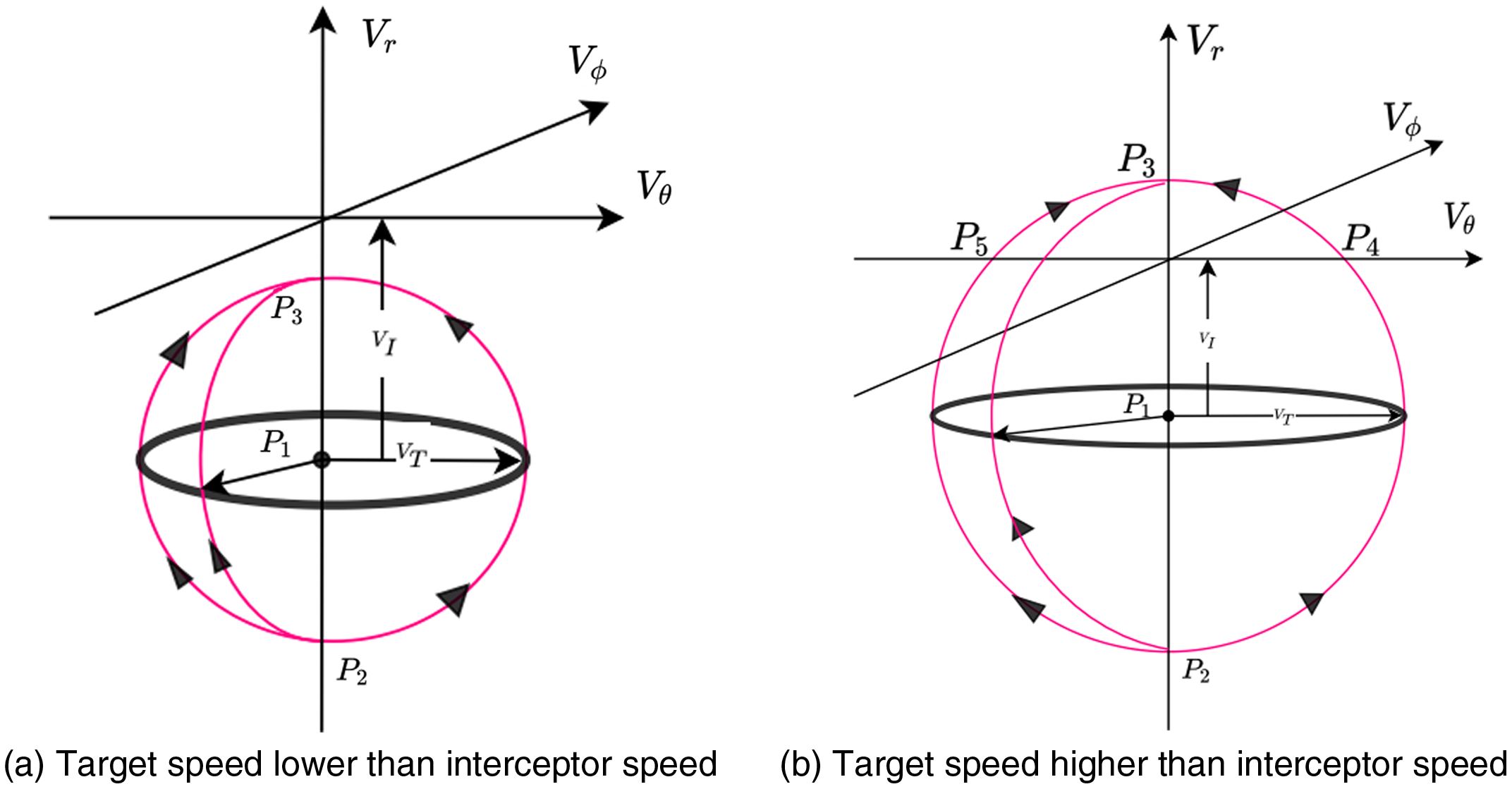
Figure 4. Trajectory in $V_{\theta }, V_{\phi }, V_{r}$
space.
$V_{\theta }, V_{\phi }, V_{r}$
space.
In the ( $V_{\theta }$
,
$V_{\theta }$
, $V_{\phi }$
,
$V_{\phi }$
, $V_{r}$
) space, if the velocity of the interceptor is higher than the target, the sphere will intersect the
$V_{r}$
) space, if the velocity of the interceptor is higher than the target, the sphere will intersect the $V_{R}$
axis at a negative value of
$V_{R}$
axis at a negative value of $V_{R}$
. As shown in Fig. 4(a), the trajectory will intercept the
$V_{R}$
. As shown in Fig. 4(a), the trajectory will intercept the $V_{R}$
axis at
$V_{R}$
axis at $P_{3}$
, and leading to the interception of the target with no miss distance. If the velocity of the target is higher than the velocity of the interceptor, then there will be a miss distance during the engagement. The possible initial conditions in (
$P_{3}$
, and leading to the interception of the target with no miss distance. If the velocity of the target is higher than the velocity of the interceptor, then there will be a miss distance during the engagement. The possible initial conditions in ( $V_{\theta }$
,
$V_{\theta }$
, $V_{\phi }$
,
$V_{\phi }$
, $V_{r}$
) space which leads to interception with no miss distance, that is, capturability region of the interceptor for this guidance algorithm, is shown in Fig. 5.
$V_{r}$
) space which leads to interception with no miss distance, that is, capturability region of the interceptor for this guidance algorithm, is shown in Fig. 5.

Figure 5. Capturability zone of the guidance algorithm.
So, it can be concluded that if the velocity of the interceptor is greater than the target, the component of relative velocities perpendicular to the LOS goes to zero, and at that point, the component along the LOS is negative, that is,
 \begin{equation} V_{r} \lt 0 \quad V_{\theta } =0 \quad V_{\phi } =0 \end{equation}
In that case, from of (21) and (23),
 \begin{equation} V_{\theta }= -R \frac{y_{T}\dot{x}_{T}-x_{T}\dot{y}_{T}}{x_{T}^2+y_{T}^{2}} \frac{y_{T}}{\sqrt{x_{T}^2+ y_{T}^2+f^2}} =0 \end{equation}
 \begin{equation} V_{\phi }= -\frac{R}{\sin \phi } \frac{x_{T}(x_{T} \dot{y}_{T}-y_{T}\dot{x}_{T})+f^2 \dot{y}_{T}}{(x_{T}^{2} +y_{T}^2+f^{2})^{1.5}} =0 \end{equation}
Therefore, from (37), at that point, $y_{T} =0$
, or,
$y_{T} =0$
, or, $y_{T}\dot{x}_{T}-x_{T}\dot{y}_{T}=0$
. If
$y_{T}\dot{x}_{T}-x_{T}\dot{y}_{T}=0$
. If $y_{T} =0$
; then
$y_{T} =0$
; then $\dot{y}_{T} =0$
, and therefore from (38),
$\dot{y}_{T} =0$
, and therefore from (38), $x_{T} =0$
. If
$x_{T} =0$
. If $y_{T}\dot{x}_{T}-x_{T}\dot{y}_{T}=0$
, then from Eq. (38),
$y_{T}\dot{x}_{T}-x_{T}\dot{y}_{T}=0$
, then from Eq. (38), $\dot{y}_{T}=0$
. After substituting
$\dot{y}_{T}=0$
. After substituting $y_{T}\dot{x}_{T}-x_{T}\dot{y}_{T}=0$
and
$y_{T}\dot{x}_{T}-x_{T}\dot{y}_{T}=0$
and $\dot{y}_{T}=0$
, we get
$\dot{y}_{T}=0$
, we get $\dot{x}_{T} =0$
, in that case
$\dot{x}_{T} =0$
, in that case $x_{T}$
and
$x_{T}$
and $y_{T}$
is a stationary point and the value is equal to zero. Clearly, if the speed of the interceptor is higher than the target during the engagement process, the pixel location of the target centre (
$y_{T}$
is a stationary point and the value is equal to zero. Clearly, if the speed of the interceptor is higher than the target during the engagement process, the pixel location of the target centre ( $x_{T}$
,
$x_{T}$
, $y_{T}$
) moves towards the centre
$y_{T}$
) moves towards the centre $(0,0)$
of the image plane following the proposed guidance strategy.
$(0,0)$
of the image plane following the proposed guidance strategy.
4. Simulation
A ROS package corresponding to the algorithm is developed in C++ and tested on the environment simulated by Gazebo. The IRIS drone is used as the airframe for the interceptor and target, while the whole set-up is run on a PX4 flight stack as a SITL simulation. The interception scenario of a moving target and a manoeuvring target is simulated to check the performance of the algorithm. The controller of the IRIS drone is subjected to the desired velocity and yaw rate commands generated from the proposed guidance algorithm.
In the case of moving target interception, the target UAV moves in a straight line at a speed of 2 m/s with the interceptor speed of 2.5 m/s. The engagement scenario is shown in Fig. 6(a), the interceptor UAV starts from position $S_{A}$
, while the target UAV starts from position
$S_{A}$
, while the target UAV starts from position $S_{T}$
. The variation of LOS is plotted in Fig. 7(a), where LOS separation distance is calculated between the camera centre and target ball centre. The initial LOS separation distance is 10 m, and the value of miss distance is found to be 0.02 m. The commanded yaw rates and commanded velocities are plotted in Fig. 7(b) and Fig. 8(a). We can observe that the high-frequency components of the desired velocity command are within a reasonable limit, and a small noise component is expected while obtaining the line-of-sight between the target and the camera centre. The corresponding variation of commanded acceleration is plotted in Fig. 8(b) for reference as most of the standard guidance algorithm generates desired accelerations. As the controller of the interceptor UAV is designed based on the desired velocity command, the high-frequency components of the accelerations do not affect the controller loop. The commanded velocities and actual velocities during the interception are shown in Fig. 9.
$S_{T}$
. The variation of LOS is plotted in Fig. 7(a), where LOS separation distance is calculated between the camera centre and target ball centre. The initial LOS separation distance is 10 m, and the value of miss distance is found to be 0.02 m. The commanded yaw rates and commanded velocities are plotted in Fig. 7(b) and Fig. 8(a). We can observe that the high-frequency components of the desired velocity command are within a reasonable limit, and a small noise component is expected while obtaining the line-of-sight between the target and the camera centre. The corresponding variation of commanded acceleration is plotted in Fig. 8(b) for reference as most of the standard guidance algorithm generates desired accelerations. As the controller of the interceptor UAV is designed based on the desired velocity command, the high-frequency components of the accelerations do not affect the controller loop. The commanded velocities and actual velocities during the interception are shown in Fig. 9.

Figure 6. Trajectories of the interceptor UAV and target.
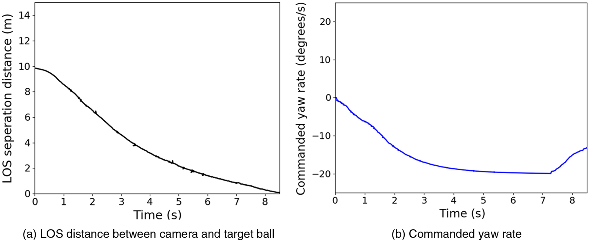
Figure 7. Variation in LOS and commanded yaw rate: Target in straight line path.
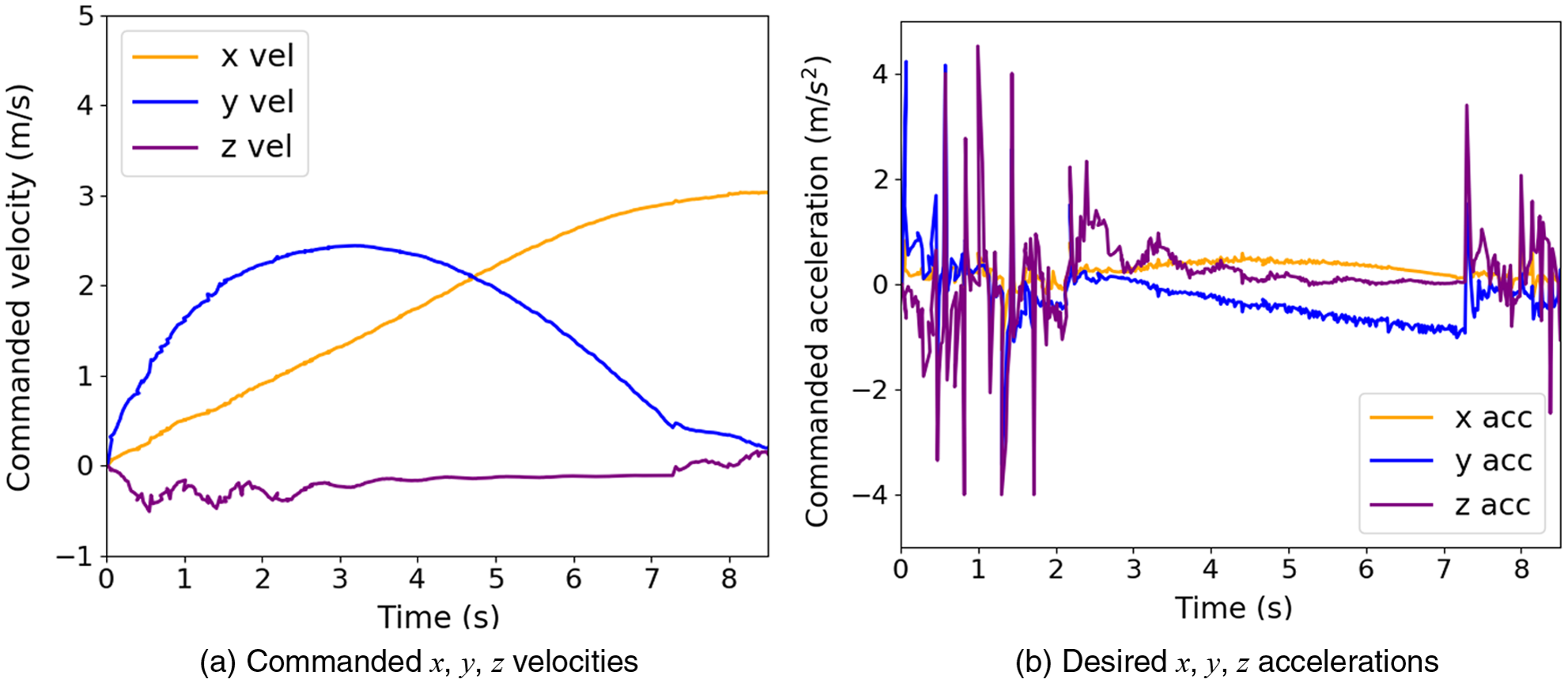
Figure 8. Commanded velocities and corresponding desired accelerations: Target in straight line path.
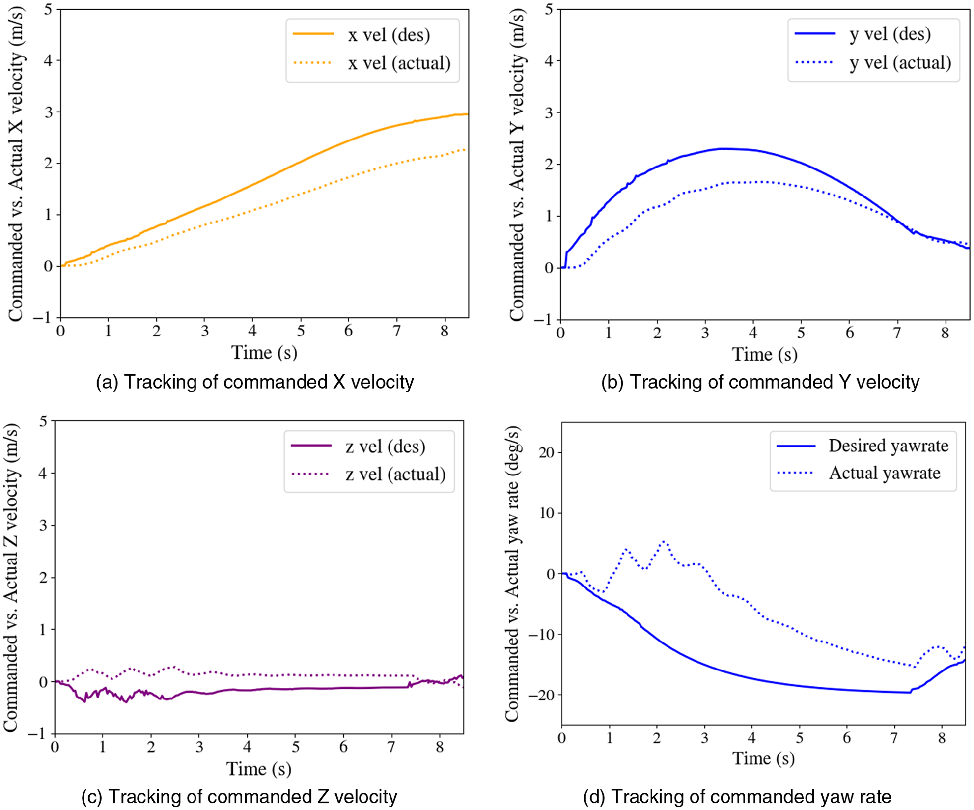
Figure 9. Tracking of guidance commands.
In the case of manoeuvring target interception, the target UAV is programmed to move in a circular path of radius 15 m at speed of 2 m/s. As shown in Fig. 6(b), the interceptor UAV starts from position $S_{A}$
at the centre of the circular path, while the target UAV starts from position
$S_{A}$
at the centre of the circular path, while the target UAV starts from position $S_{T}$
. As shown in Fig. 10(a), LOS separation distance goes to 0.01 m from the initial value of 15.5 m. Further, the plots for the commanded velocity, acceleration and yaw rate are shown in Fig. 10(b), 11(a), and (b), respectively. The simulation videosFootnote
1
demonstrate the effectiveness of the developed guidance algorithm.
$S_{T}$
. As shown in Fig. 10(a), LOS separation distance goes to 0.01 m from the initial value of 15.5 m. Further, the plots for the commanded velocity, acceleration and yaw rate are shown in Fig. 10(b), 11(a), and (b), respectively. The simulation videosFootnote
1
demonstrate the effectiveness of the developed guidance algorithm.

Figure 10. Commanded yaw rate and variation in LOS: Target in circular path.

Figure 11. Commanded velocities and corresponding desired accelerations: Target in circular path.
5. Hardware description and experimental results
The efficiency of the proposed algorithm is checked in an outdoor environment for an engagement scenario where the target ball is intercepted using a specific area of manipulator attached to a drone. The developed algorithm is implemented using a DJI M600 Pro drone with an indigenously designed manipulation mechanism (see Fig. 12) and a monocular camera. Details of the manipulator mechanism are reported in ref. [Reference Vidyadhara, Tony, Gadde, Shuvrangshu Jana, Bhise, Sundaram and Ghose36]. The overall operation management system design for the multi-drone system against various classes of targets is given in detail in ref. [Reference Tony, Shuvrangshu Jana, Bhise, Krishnapuram and Ghose37]. The drone autopilot (DJI A3 Pro flight controller) is equipped with GPS, an altimeter, and an inertial measurement unit (IMU) consisting of an accelerometer, magnetometer, and a gyroscope. The GPS is used for measuring global position, the altimeter is used for measuring the altitude, the camera is used to obtain the target information, and the IMU is used to estimate the attitudes of the vehicle. The input to the guidance algorithm is the pixel coordinates of the target in the image frame, the interceptor’s attitude, the focal length of the camera, and the rotation matrix from the camera frame to the inertial frame. The pixel coordinates of the target, interceptor’s attitude, and the transformation are obtained in real-time, whereas the camera’s focal length is estimated prior to the experiment. The pixel coordinates of the target are obtained from captured images using a monocular camera. The focal length of the used monocular camera is estimated from camera calibration. The rotation matrix is obtained using the attitudes of the interceptor UAV, and these attitudes are estimated using information from IMU.

Figure 12. Hardware architecture.
The camera is placed at the centre of the gripper of the manipulator. The camera used is industrial grade See3CAM 130, a 4K USB monocular camera. The computations are done in real-time onboard using NVIDIA Jetson TX2. The guidance commands in terms of desired velocity and yaw rate are computed in the NVIDIA Jetson TX2, and the commanded values are fed to the DJI A3 Pro flight controller to generate the motor PWM. The vision module locates the ball in three phases, namely search, track, and grab. In the search phase, the target UAV’s position is identified, and it is used to search for the ball attached to the UAV using colour segmentation. The tracking phase uses Kalman filter trackers to narrow down the region of interest in the subsequent frames. A wedge-shaped search region for the ball is considered based on UAV location and ball depth information from the previous frame. The ball depth is approximated, assuming the known dimension of the ball. In the final grab phase, as the UAV goes near the ball, the target UAV may go out of the camera’s field of view (FoV), and then, a square-shaped region is used around the predicted ball’s position to track the ball without any misses. The proposed detection method is able to detect a ball of 100 mm diameter from a distance of 20 m.

Figure 13. Snapshots from flight tests showing the frames, where target capture is accomplished.
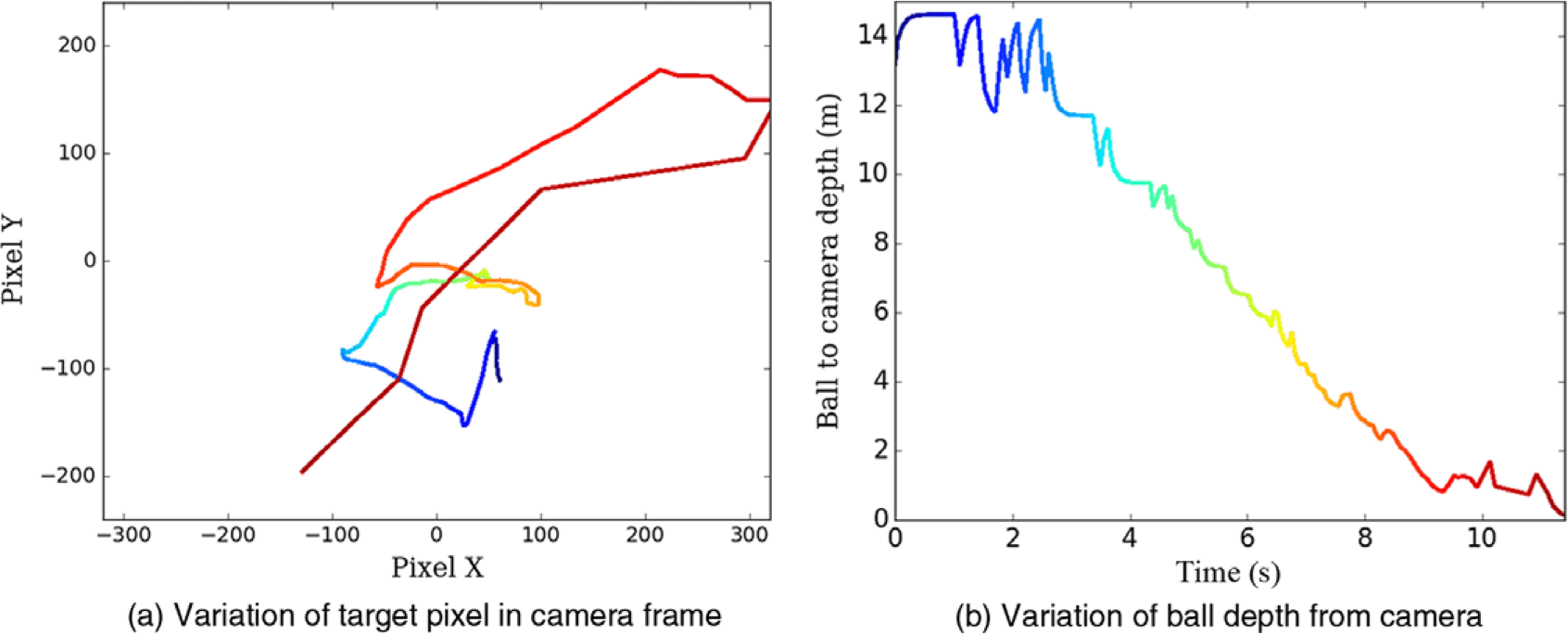
Figure 14. Interception of manoeuvring target: hardware implementation (a) Variation of target pixel (image plane: 640 $\times$
480) and (b) Variation of ball depth.
$\times$
480) and (b) Variation of ball depth.

Figure 15. Commanded vs actual states.

Figure 16. Attitude of UAV during the mission.

Figure 17. Snapshots of engagement from camera attached to UAV (a) Ball depth = 8.92 m and (b) Ball depth = 4.16 m.
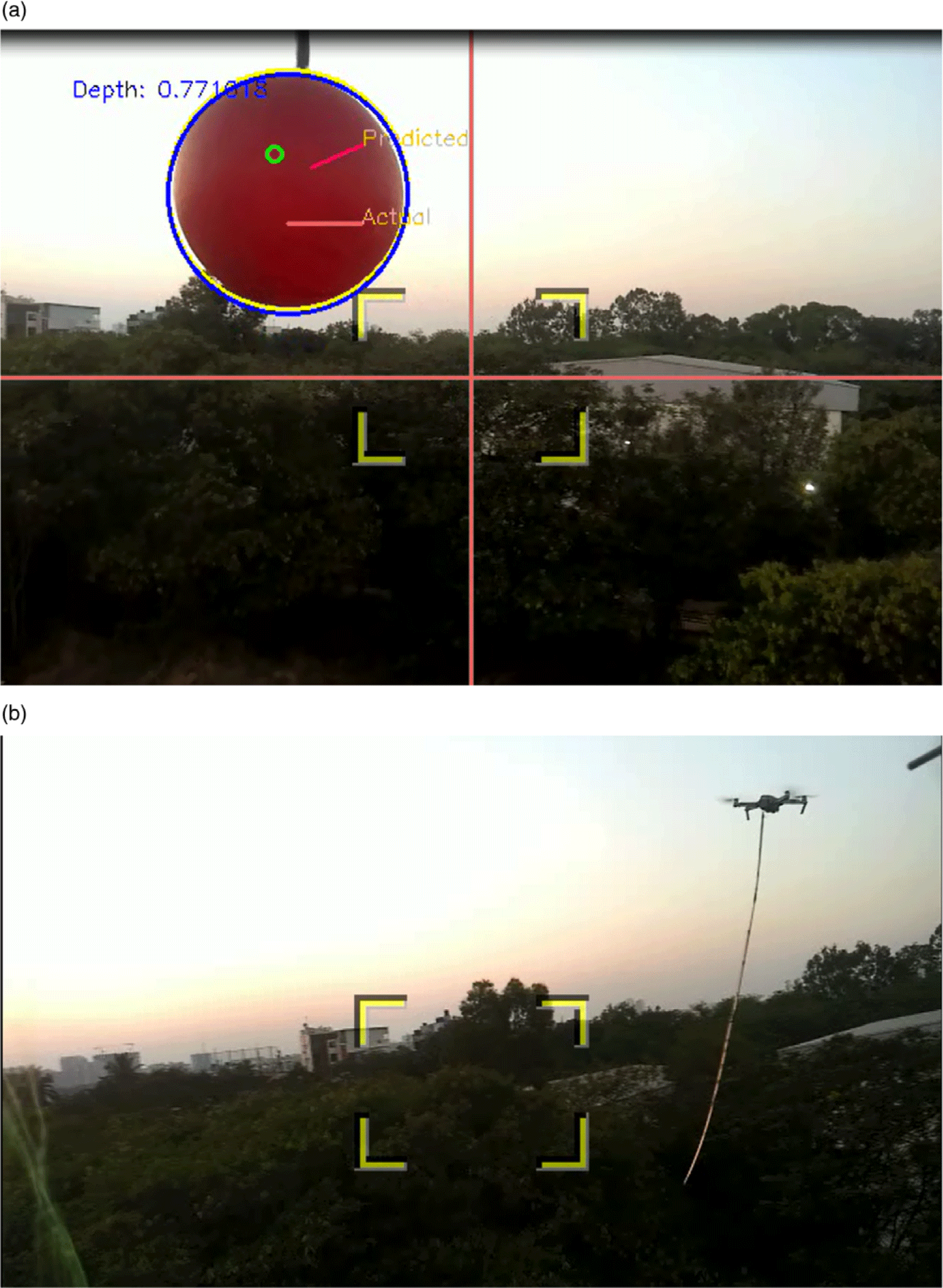
Figure 17. (Contd.) Snapshots of engagement from camera attached to UAV (a) Ball depth = 0.77 m and (b) After interception.
Once the detection module is finalised, we have conducted experiments before finalising the proposed module. We have conducted experiments using path planning and PN guidance-based approach after estimation of target position (PBVS techniques) and also a controller based on the error in the current target pixel and the desired target pixel. In a path planning-based approach, the desired velocity is calculated based on the predicted target location, and desired yaw rate is obtained to keep the target in the field of view. However, we observed that miss distance increases with the increase in target velocity as there is considerable uncertainty in the target location at the predicted time of interception. The path planning-based approach is found to be suitable only for the slow-moving target. We have also used the PD-based controller to obtain desired forward and lateral velocity based on the interceptor. However, the interception efficiency is poor in this case due to the high noise of the target pixel in the outdoor environment. In PN guidance-based approach, the desired velocity is computed using the PN guidance, and the yaw rate is computed to keep the target in the field of view. However, this method fails to provide interception accuracy in the terminal phase due to the error in depth estimation. Also, due to the nature of PN guidance, it was difficult to keep the target in the field of view using only the yaw rate, as the interceptor was not looking at the target. We concluded that interception estimation using target depth of pixel error would have low efficiency in the outdoor environment. Therefore, we focused on developing a guidance strategy based on inputs that are not affected by high uncertainty.
The proposed guidance algorithm is initially tested for stationary targets, and some of the gain parameters of the yaw rate command are tuned appropriately. The gain of the PD controller is tuned separately, keeping the UAV in a fixed position and observing its responses while tracking a circular moving target. The camera is rigidly fixed to the UAV manipulator system. The initial distance of the target from the UAV is kept less than the maximum distance at which the target could be detected. The UAV is able to successfully intercept moving as well as manoeuvring targets. The sequence of snapshots of a successful engagement scenario with a moving target and manoeuvring target is shown in Fig. 13. In case of interception with manoeuvring target, the variation of the target location in the image plane is shown in Fig. 14(a). The corresponding variation in depth of ball from the camera is plotted in Fig. 14(b).
The different colour is used to show the variation of depth related to the movement of the target in the image plane. Clearly, the distance between the ball and the Camera centre goes to zero at the time of interception. The variation of target location in the image plane is not smooth due to the manoeuvring target. Similarly, the non-smooth variation in ball depth is observed due to uncertainty in the measurement of ball depth and manoeuvring target. The commanded velocities and yaw rates derived from the guidance algorithm are shown in Fig. 15. The corresponding actual velocities and the yaw rates are also shown in Fig. 15. The actual velocities are measured using GPS measurements, and the yaw rate is obtained from the IMU. The variation of the attitude of the UAV during the engagement is shown in Fig. 16. Clearly, the system attitudes remain bound during the engagement. The sequence of snapshots of frames observed from the camera during the engagement is shown in Fig. 17. Videos of engagement scenarios are included in this linkFootnote 2 . Videos of different experiments showing the complexities associated with the engagement scenario are shown in this linkFootnote 3 . The proposed system is tested to intercept the manoeuvring target at a speed of 5 m/s with a high success rate.
We have performed the experiments for the interception scenario for a target speed up to 8 m/s. Our proposed guidance strategy and the hardware set-up were able to intercept targets moving at speeds of 5 m/s and less with a high success rate in a tail-chase scenario. The performance efficiency reduces at higher speeds due to the low efficiency of the detection module.
As the problem statement in the paper is motivated by Challenge 1 of MBZIRC-2020, many other groups also worked in parallel to solve a similar problem [Reference Barisic, Petric and Bogdan30, Reference Zhao, Shi, Anzai, Takuzumi, Toshiya, Kita, Naoki and Kei31, Reference Cascarano, Milazzo, Vannin, Andrea and Stefano32]. In these algorithms, target depth information is used. In contrast, our approach is different from the other works as we have used only the alignment information of the target in the image frame. Also, the analysis of the vision-based 3D guidance algorithm in the relative velocity space is a novel contribution to our work. We point out that in the papers that attempt to solve a similar problem, such analysis of vision-based guidance strategy is not reported. Further, the main focus of our paper is on designing a guidance algorithm without estimation of target depth which is unlike the other approaches. The fact that we use pursuit guidance also ensures that the target is kept in the camera’s field of view, thus improving the effectiveness of the guidance algorithm. It is to be noted that the efficiency of any interception strategy depends on the efficiency of the different sub-components of the detection module, tracking module, planning module, and controller module. Apart from the efficiency of the algorithms, the overall efficiency also depends on many other factors such as the fidelity of sensors, the agility of vehicles, and delay in the feedback. Therefore, it is not possible to carry out a comparison of the efficiency of different guidance algorithms with the similar efficiency reported in the literature unless a similar hardware set-up is used in all the experiments.
6. Conclusions
This work proposed a guidance strategy for the interception of manoeuvring aerial targets using visual information and an extended manipulator mechanism. A relative velocity framework is used in the formulation of the guidance algorithm. A vision-based interception method is developed where the various scenarios of target and interceptor speeds are considered, and their impact on the engagement is discussed. It is shown that the proposed guidance algorithm keeps the target in the field of view and ensures interception for low-speed targets. Simulation results are presented along with experimental results that validate the developed guidance algorithm. The future work includes the extension of the proposed guidance algorithm for the interception of high-speed targets.
Supplementary material
To view supplementary material for this article, please visit https://doi.org/10.1017/S0263574722001096.
Acknowledgement
The authors would like to thank Aruul Mozhi Varman S., Vidyadhara B. V., and Mohitvishnu S. Gadde for their valuable inputs in system design.
Author contributions
Author SJ proposed and analysed the guidance algorithm, helped in testing and wrote the paper. Author LAT dealt with system integration, analysis, and testing of guidance algorithms and wrote the paper. Author AAB and Author VVP helped in the software implementation of the guidance algorithm. Author DG led the project, reviewed the algorithms, and wrote the paper.
Financial support
We would like to acknowledge the Robert Bosch Center for Cyber Physical Systems, Indian Institute of Science, Bangalore, and Khalifa University, Abu Dhabi, for partial financial support.
Conflicts of interest
The authors declare none.


 Open access