


Introduction
The task of designing a new product is a common problem shared by different engineering domains. While some problems faced during the design of a new product may be specific to an engineering domain, generic approaches have been investigated for support in the design task. Such approaches include, among others, knowledge-based engineering, model-based systems engineering (MBSE), as well as generative grammars and graph-based design languages.
The application of generative grammars for engineering design has long been a subject of research in the field of architecture and engineering. The use of generative grammars for engineering design falls into the field of computer-based design synthesis research. Besides the use of generative grammars for design synthesis, other research fields in computer-based design synthesis are function-based synthesis and analogy-based design (Chakrabarti et al., Reference Chakrabarti, Shea, Stone, Cagan, Campbell, Hernandez and Wood2011). Generative grammars use a vocabulary to describe the elements of the design and an associated set or rules to describe how these elements may be put together to form a valid design. The vocabulary and the associated set of rules are used to formalize the knowledge necessary to create a design. The rules consist of two parts, a left-hand side (LHS), defining the conditions under which the rule is applied, and a right-hand side (RHS), defining the transformations that should be carried out, if the conditions defined on the LHS are found. In the case of graph grammars, the LHS might define a particular graph pattern and the RHS may consists of modifications, such as additions or subtractions, that are applied to instances of this pattern in the overall graph.
According to the underlying representation, different kinds of grammars can be distinguished. Gips and Stiny distinguish between array, tree, graph, and shape grammars (Gips and Stiny, Reference Gips and Stiny1980). In their overview on generative grammars, Chakrabarti et al. (Reference Chakrabarti, Shea, Stone, Cagan, Campbell, Hernandez and Wood2011) identify graph and spatial grammars as the most common types of grammars used for engineering design. The category of spatial grammar, that is used by Chakrabarti et al., comes from the research of Krishnamurti and Stouffs (Reference Krishnamurti and Stouffs1993) and is not directly linked to the underlying representation but is used for grammars that define languages of spatial forms (Krishnamurti and Stouffs, Reference Krishnamurti and Stouffs1993). Spatial grammars may use strings, sets, graphs, or shapes as underlying representation (Krishnamurti and Stouffs, Reference Krishnamurti and Stouffs1993; Chakrabarti et al., Reference Chakrabarti, Shea, Stone, Cagan, Campbell, Hernandez and Wood2011). An overview of different applications of generative grammars is given by Antonsson and Cagan (Reference Antonsson and Cagan2001). The book by Antonsson and Cagan includes contributions by different authors on the topic of generative grammars. It includes chapters on the topic of shape grammars (Stiny, Reference Stiny2001) and the application of shape grammars for engineering design (Cagan, Reference Cagan2001).
This article focuses on graph-based representation approaches. Generally, the data representation are graphs, consisting of nodes, edges, and labels. Graph grammars, a type of generative grammar and graph-based design languages, share a graph as an underlying data structure and the fact that graph transformation is used to describe how the graph should be transformed to create a valid design. A closer examination shows that different terms are used to describe similar approaches. In this respect, “graph grammar,” “graph rewriting,” “graph transformation,” or “graph-based design language” describe approaches used for engineering design in the field of architecture and various subdomains of mechanical engineering. While it could be expected that each of these terms designates a clearly defined approach, this is not always the case.
Despite the different designations, the approaches share some characteristics. The common characteristics of these approaches are the use of a vocabulary to describe the elements of the design and an associated set of rules to describe how the elements may be put together to form a valid design. The approaches differ on how the rules are processed. Graph grammars stress the generative aspect and are used to create the so-called language of the graph grammar, that is the possible solutions derived by applying the rules of the grammar (Blostein et al., Reference Blostein, Fahmy and Grbavec1996). Other approaches might prefer a deterministic execution of the rules, where exactly one result is created for a certain input, as is the case with graph-based design languages. Graph rewriting and graph transformation merely state the mechanism of how the graph as the underlying data structure is changed. In this paper, we use the term graph transformation.
The common characteristics shared by the different approaches strongly suggest that these characteristics perform well in different settings. The advantages and disadvantages of the different approaches to use graph transformation for engineering design are considered in this review. To understand the current situation, as well as the similarity and differences of the approaches, the following questions need to be answered:
• For what examples has graph transformation been used in engineering design?
• How are the vocabulary and the rules documented?
• How are the vocabulary and the rules processed to derive valid designs?
• What research gaps need to be addressed?
In this study, these questions are answered through a literature review. In total, 48 journal articles published between 2010 and 2020 in 24 different journals were reviewed. The paper has the following structure: Section “Methodology” describes how the different journal articles were selected. In Section “Research areas,” the reviewed literature is categorized into the two categories: “method development” and “application of graph transformation” in engineering design. Section “Documentation of the production system” examines how the vocabulary and the rules are documented. In Section “Processing,” different approaches to process the vocabulary and the rules in order to create valid designs are presented. Section “Future research directions” presents research gaps that need to be addressed, followed by the paper's conclusion.
Methodology
In this paper, we discuss the application of graph transformation systems for engineering design for the period of 2010–2020. Graph transformation systems are used in many fields. In the context of engineering design, the research on the application of graph transformation may be published in journals that focus on the application of information technology in engineering or in journals that focus on a special engineering field in which the application of graph grammars is investigated.
In order to avoid overlooking relevant research, the search for articles consisted of the following steps as indicated by Figure 1. The first step was a broad search in the Web of Science database. The keywords for the topic search were design language, design languages, graph grammar, graph grammars, graph rewriting, graph transformation, graph transformations, graph-based design language, and graph-based design languages. The search was limited to journal articles in English published between the years 2010 and 2020 in journals listed in the Science Citation Index Expanded (SCI-Expanded), the Social Sciences Citation Index (SSCI), the Arts & Humanities Citation Index (A&HCI), or the Emerging Sources Citation Index (ESCI). This time period was chosen because the paper by Chakrabarti et al. discussing graph grammars in the context of computational design synthesis was submitted in 2010 (Chakrabarti et al., Reference Chakrabarti, Shea, Stone, Cagan, Campbell, Hernandez and Wood2011). We had two criteria to determine if an article should be included in the review:
• Does the research show the development of new methods for the application of graph transformation for engineering design?
• Does the research show how graph transformation can be applied for a specific engineering design problem?

Fig. 1. Selection process for the papers included in the review.
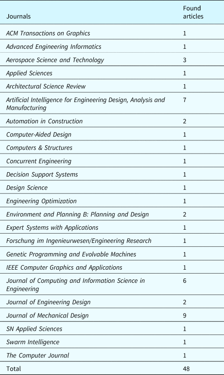
If the research meet one of these criteria, we included the journal article in the review. To thoroughly check the relevance of the found articles, first the abstracts of the articles were read. If the article seemed to meet one or both of the criteria, based on reading the abstract, we read the article to check if the article was relevant for the review. Table 1 shows the number of articles returned for a specific keyword and the number of articles included in the review. Due to the general search terms, a large number of articles was found. In the first step, 41 journal papers were identified. The journals, in which these 41 papers were published, formed the basis for a more detailed search in the individual journal databases.
Table 1. Web of Science search results

The aim of the second step was to find articles that might have been missed in the search of the Web of Science database. For the second step, journals with a 5-year impact factor higher than 1.0 for the year 2019 were selected from the journals identified in the Web of Science search. In these journals, a search in the individual journal database was conducted. The search of the individual journal databases used the same parameters and the same procedure as the Web of Science search. In the journal search, 271 articles were returned as search results. The articles where screened using the same method as during the search in the Web of Science database. If an article met one of the criteria, it was included in the review. Seven additional articles were identified for the review through the search in the individual databases of the different journals. In total, 48 journal articles were found. These articles 48 journal articles include one review article, the article by Chakrabarti et al. (Reference Chakrabarti, Shea, Stone, Cagan, Campbell, Hernandez and Wood2011).
Table 2 gives an overview of the number of articles per journal considered in this review. In many journals, just one article was found for the 10-year period considered in this review. This reinforces the need for an overview, since the research is dispersed among a large number of journals. In the next step, the articles were categorized. The categorization was done based on the content of the articles. In the following step, the authors analyzed common themes in the use of graph transformation for engineering design.
Table 2. Found articles by journal
Research areas
To give an overview of the reviewed articles, the articles are grouped according to the research content. The two main categories are “method development” and “application of graph transformation” for engineering design. For some articles, these two categories are not mutually exclusive, since some authors present a new method to use graph transformation for engineering design and the application of this new method for a certain engineering problem. In these cases, the research is presented in both categories. Table 3 gives an overview of the categories and subcategories used to classify the articles as well as the number of articles in each category.
Table 3. Categories used to classify the articles

Method development
In order to use graph transformation for engineering design, new methods have been proposed by different researchers. The development of new methods can be motivated by shortcomings of current software applications. The research in this category is classified in the subcategories “representation” and “processing.” Research that focuses on issues concerning the definition of the vocabulary and the rules is presented in the subcategory “representation.” In the subcategory “processing,” new methods for the processing of the vocabulary and the rules are presented.
Representation
The simplest representation of a graph consists of nodes and edges. The vocabulary and the corresponding rules need to be defined to use graph transformation for engineering design. One difficulty in the representation of a design problem is the formalization of the relevant knowledge and breaking down the system into parts that can be easily managed. For larger projects, it can be a challenge to represent the vocabulary in a concise manner. The use of the concepts of object-oriented design have been investigated in order to keep the description of the vocabulary manageable. Metamodels have been used to describe the vocabulary. In this context, the term metamodel refers to a model that defines the elements from which another model may be instantiated. The approaches include the use of a metamodel to implement the function-behavior-structure representation (Helms and Shea, Reference Helms and Shea2012), and the use of abstraction ports to connect instances on the functional and the behavioral level, based on physical effects described in the bond-graph methodology (Helms et al., Reference Helms, Schultheiss and Shea2013). Metamodels can also be defined for particular aspects shared by many different design tasks. This is illustrated by the so-called “abstract geometry,” a description of geometry using the Unified Modeling Language (UML) class diagram that allows instances of the classes to be mapped to the corresponding implementation in CAD programs (Schmidt and Rudolph, Reference Schmidt and Rudolph2016). Newer research presents approaches where the classes used to describe product design also contain methods and interfaces (Vogel and Arnold, Reference Vogel and Arnold2020).
The use of a metamodel has an impact on the rules. If inheritance is used in the definition of the metamodel, very generic rules can be defined that allow extending the metamodel without resulting in changes to the defined rules (Helms and Shea, Reference Helms and Shea2012). In order to successfully apply graph transformation in engineering design, designers or engineers need to understand how rules interact with each other and how rules relate to certain objective. Different methods have been developed to aid designers in defining rules, the “Grammar Rule Analysis Method” (Königseder and Shea, Reference Königseder and Shea2014) and the “Network-Based Rule Analysis Method” (Königseder et al., Reference Königseder, Stanković and Shea2016). A good understanding of how the rules interact is necessary to avoid confluence. Confluence occurs if the same graph can be created with the application of different rules or rules applied in a different order. To avoid confluence in a collaborative design environment, the dynamic rule independence analysis method has been developed (Eichhoff and Roller, Reference Eichhoff and Roller2016). Generally, the vocabulary and the rules are created by a designer or engineer. In order to make this task easier, the induction of graph grammars for engineering design from existing datasets has been proposed (Whiting et al., Reference Whiting, Cagan and LeDuc2018).
Processing
The next identified subcategory covers how the vocabulary and the rules are processed and how good solutions are found during the search process. The majority of the research in this subcategory was developed for graph grammars.
Graph grammars are used to create the language of the grammar, that is the possible solutions described by the vocabulary and the associated rules. When used for engineering design, it is not always possible to create the complete language, especially for cases where computationally expensive evaluations are part of the design process. For this reason, a good understanding of the interaction of different rules and the exploration of the design space is necessary. Visualizations have been used to support designers in developing a grammar (Königseder and Shea, Reference Königseder and Shea2016). For graph grammars, transition graphs have been used to analyze how rules interact and how the design space is explored (Königseder et al., Reference Königseder, Stanković and Shea2016).
Other researchers are concerned with different strategies to guide the search process. One way to guide the search process to find well-performing solutions quickly is by using different sets of rules. Using a set of lower-tier rules that make minor changes to the design and higher-tier rules, which consist of several lower-tier rules, was investigated for truss design and wave energy converter design (Puentes et al., Reference Puentes, Cagan and McComb2019). A similar approach examined strategies to use sets of rules with the BURST algorithm (Königseder and Shea, Reference Königseder and Shea2015). Königseder and Shea distinguish between topologic and parametric rules. Topologic rules are rules that change the product architecture, and parametric rules are rules that change the parameters of components (Königseder and Shea, Reference Königseder and Shea2015). Other authors propose the use of special algorithms to guide the search process. The developed algorithms include the “topologic and parametric tune and prune” ((TP) $^{2}$) algorithm (Patel and Campbell, Reference Patel and Campbell2010), a stochastic tree-search algorithm to interactively asses proposed solutions (Campbell et al., Reference Campbell, Rai and Kurtoglu2012), and the “Graph Heuristic Search” algorithm (Zhao et al., Reference Zhao, Xu, Konaković-Luković, Hughes, Spielberg, Rus and Matusik2020).
Transferring the problem to another domain can also be used to find valid solutions. If the problem can be redefined as a problem of Boolean satisfiability, a Boolean Satisfiability Solver can be used to find valid solutions (Münzer et al., Reference Münzer, Helms and Shea2013). Using bond graphs, the resulting solutions can be simulated (Muenzer and Shea, Reference Muenzer and Shea2017).
Design tasks can be broken down to consist of separate domains. For each domain, separate graph transformation systems with a separate vocabulary and rules may be used. Often the vocabulary is not completely distinct, since changes concerning one domain lead to changes in other domains. The synchronization of rule application concerning shared elements has been investigated to avoid cases where the rule application in one domain would lead to illegal states concerning the other domain (Kotulski et al., Reference Kotulski, Sędziwy and Strug2014). Rules are used to make a particular change to the graph representing the design. This can lead to situations where rules can be very big. A possible solution is to use break these large rules into several smaller rules that need to be executed in a sequence. However, these rule sequences can be difficult to maintain and prohibit code reuse. In order to deal with this issue, methods have been introduced to better support the design of complex products with graph-based design languages (Vogel and Arnold, Reference Vogel and Arnold2020). As a result, design steps that have previously been explicitly modeled in one or several rules can now be hidden in methods, enabling better information hiding (Vogel and Arnold, Reference Vogel and Arnold2020).
Application of graph transformation
A large part of the reviewed research falls into the category of how graph transformation can be applied for a specific engineering design problem. In this category, graph transformation is applied to problems of different engineering fields and at different stages of the product development process. In order to give an overview, the research activities were grouped in three subcategories: the domain of engineering, the domain of architecture, and the use of graph transformation in the development of new approaches for shape grammars.
Engineering
In engineering, graph transformation can be applied to many different design tasks and in different stages of product development process. This can include the early stages of product development. An example for the use of graph transformation in the very early stages of product development is the use of graph transformation to automatically create a technology compatibility matrix, which is used to determine which technologies should be applied in an engineering project (Roelofs and Vos, Reference Roelofs and Vos2020).
Many examples are focused on the conceptual design stage of product development. Graph grammars have been used for the design of a coffee grinder, which covers the design process starting with the initial definition of a system boundary to the final design (Kurtoglu et al., Reference Kurtoglu, Swantner and Campbell2010). Other research focuses on the design of sheet metal parts (Patel and Campbell, Reference Patel and Campbell2010), fluid channels (Hooshmand and Campbell, Reference Hooshmand and Campbell2014), or trusses (Hooshmand and Campbell, Reference Hooshmand and Campbell2016). Further examples include the case where graph grammars have been used in an automated design process to optimize the design at the conceptual stage for tank suspension systems (Li and Zhao, Reference Li and Zhao2015). Graph grammars have also been used in the design of different robots, where they have been used for the design of passive dynamic brachiating robots (Stöckli and Shea, Reference Stöckli and Shea2017) and for the design of robot structures for different terrains (Zhao et al., Reference Zhao, Xu, Konaković-Luković, Hughes, Spielberg, Rus and Matusik2020).
Often there is just one example of the use of graph transformation for a particular design task. This makes it difficult to evaluate these implementations. In the case of the design of gear systems, this situation is different. There are several examples how graph transformation has been applied to design different gear systems. Gearbox synthesis was used as an example to create better search methods using GrGen.NET (Königseder and Shea, Reference Königseder and Shea2015; Königseder et al., Reference Königseder, Stanković and Shea2016). Königseder et al. also give an overview where graph grammars have been used in the past to design gear systems (Königseder et al., Reference Königseder, Stanković and Shea2016). A solution that creates the possible configurations for simple, compound, bevel, and worm gears has been implemented using GraphSynth (Swantner and Campbell, Reference Swantner and Campbell2012).
Graph-based design languages have also been used to design gears for electrical trains (Holder et al., Reference Holder, Zech, Ramsaier, Stetter, Niedermeier, Rudolph and Till2017, Reference Holder, Rudolph, Stetter and Salander2019). In this context, graph-based design languages have been used for the management of the requirements (Holder et al., Reference Holder, Zech, Ramsaier, Stetter, Niedermeier, Rudolph and Till2017) and for a process that incorporates special gear design software used in the industry (Holder et al., Reference Holder, Rudolph, Stetter and Salander2019).
The design of the FireSat satellite is a comprehensive example that shows the potential of graph transformation (Gross and Rudolph, Reference Gross and Rudolph2016a, Reference Gross and Rudolph2016b, Reference Gross and Rudolph2016c). The authors describe how the vocabulary of the satellite is modeled using the UML, how rules are used to describe graph transformations, and how different design alternatives are explored (Gross and Rudolph, Reference Gross and Rudolph2016b). An emphasis is put on how geometry and simulations are modeled (Gross and Rudolph, Reference Gross and Rudolph2016a). The design of the satellite shows how thermal simulations and cable routing can be automated (Gross and Rudolph, Reference Gross and Rudolph2016a) and how different design cycles can be solved iteratively (Gross and Rudolph, Reference Gross and Rudolph2016c).
The design process does not always need to be fully automated. Some researchers explicitly call for a human-in-the-loop approach to show designers the consequences of design decisions at the conceptual design stage (Arlitt and Bossuyt, Reference Arlitt and Bossuyt2019). In Arlitt and Bossuyt's research, graph transformation was used to generate alternative functional models of an electrical power system to generate solutions with lower failure rates (Arlitt and Bossuyt, Reference Arlitt and Bossuyt2019). Another example can be found in civil engineering, where graph transformation has been used for the semi-automatic model generation of shield tunnels (Vilgertshofer and Borrmann, Reference Vilgertshofer and Borrmann2017).
Graph transformation can be used in the context of manufacturing. How technical processes can be modeled with the use of graph grammars is shown with the examples of riveting and welding (Stanković et al., Reference Stanković, Štorga, Shea and Marjanović2013). Graph grammars have been used to determine if solid models can be manufactured (Fu et al., Reference Fu, Eftekharian and Campbell2013) and for defining lathe operations (Fu et al., Reference Fu, Eftekharian, Campbell and Kurtoglu2014). A case study from spindle production has been used to show how graph transformation systems can be used to automate the production process planning for product families (Zhang and Jiao, Reference Zhang and Jiao2013). Graph grammars have also been used to control the self-assembly of robotic modules (Haghighat and Martinoli, Reference Haghighat and Martinoli2017). It has been shown that the rulesets for self-assembly of robotic modules can be automatically created using algorithms (Haghighat and Martinoli, Reference Haghighat and Martinoli2017).
Architecture
For the period covered in this review, the majority of the research on the application of graph transformation to find valid engineering designs is situated in the field of engineering. Next to engineering, architecture is also an important field. In contrast to engineering, graph transformation is not only used for the creation of new designs, but also for the analysis of existing designs.
In the analysis of existing designs, the relationship between rooms is considered. The justified plan graph used in space syntax is used to analyze house designs of the architect Glenn Murcutt and a graph grammar is used in combination with a 3D shape grammar to create the analyzed designs as well as alternatives to the analyzed designs that adhere to the discovered design principles (Lee et al., Reference Lee, Ostwald and Gu2015). A reserved graph grammar is used to confirm, whether a design for a house, represented by a graph depicting the paths in a house conforms with a set of constraints (Wang et al., Reference Wang, Liu and Zhang2019). Examples of house designs by Frank Lloyd Wright are used, to show that it is possible to validate the designs and to create new path-graphs that conform to a style (Wang et al., Reference Wang, Liu and Zhang2019).
Part of architectural design is defining the shape of a building or of building elements. A graph representation that is very close to geometry, where each node represents a point in 3D space has been used for graph grammars in combination with evolutionary computing for 3D beam design (McDermott, Reference McDermott2013). Other researchers focus on assisting designers in building design. Graph transformation has been used to create different design solutions and to check whether these solutions meet predefined criteria (Ślusarczyk, Reference Ślusarczyk2018). In this research, graph requirements have been used to validate design solutions for floor layouts created by hierarchical layout graph grammars (Ślusarczyk, Reference Ślusarczyk2018). Existing floor plans are used in combination with graph transformation to design floor plans with identical connectivity, while giving user the possibility of add or remove rooms (Wang et al., Reference Wang, Yang and Zhang2018). In another approach, designs for floor plans are also generated based on a set of requirements using graph grammars (Wang and Zhang, Reference Wang and Zhang2020). User requirements can include plan size, the aspect ratio of the rooms, as well as the room orientation (Wang and Zhang, Reference Wang and Zhang2020).
Shape grammars
Several researchers have used graph transformation to implement shape grammars. The Palladian grammar, originally developed by Stiny and Mitchell (Stiny and Mitchell, Reference Stiny and Mitchell1978) for the design of Palladio's villas, has been implemented using a graph grammar (Grasl, Reference Grasl2012). Grasl first used the graph grammar to create a graph representing the design which was transformed into a 2D plan in a second step. Since the graph depicts a Palladian design, certain conventions for the transformation of the graph into a 2D plan can be assumed (Grasl, Reference Grasl2012). Another example is a graph grammar, developed to implement the Rabo-de-Bacalhau transformation grammar (Strobbe et al., Reference Strobbe, Eloy, Pauwels, Verstraeten, Meyer and Campenhout2016). According to Strobbe et al., input for the grammar can be created in a CAD program and can be transferred as an IFC file. The graph grammar implementation of the Rabo-de-Bacalhau grammar uses geometric and symbolic entities (Strobbe et al., Reference Strobbe, Eloy, Pauwels, Verstraeten, Meyer and Campenhout2016).
GRAPE is a general approach that uses graph grammars to implement shape grammars (Grasl and Economou, Reference Grasl and Economou2013). GRAPE uses GrGen.Net as a backend for the graph transformation (Grasl and Economou, Reference Grasl and Economou2018). Grammars can be executed in different CAD programs, as well as a web interface, while rules are described using GrGen.NET or a visual editor (Grasl and Economou, Reference Grasl and Economou2018). Examples for implemented shape grammars were given in a recent publication (Grasl and Economou, Reference Grasl and Economou2018). Graph grammars have also been used to implement a tool that allows design space exploration of shape grammars (Strobbe et al., Reference Strobbe, Pauwels, Verstraeten, Meyer and Campenhout2015).
Documentation of the production system
Implementations should not only be well documented to facilitate reimplementation: The primary reason for documentation is to provide a better understanding of the documented system (Parnas and Clements, Reference Parnas and Clements1986). The vocabulary and the rules should be documented in a precise manner to provide a better understanding for coworkers and, in the case the results are published, to the readers of the article. The management of research data should adhere to the FAIR principles, that data is findable, accessible, interoperable, and reuseable (Wilkinson et al., Reference Wilkinson, Dumontier, Aalbersberg, Appleton, Axton, Baak, Blomberg, Boiten, da Silva Santos, Bourne, Bouwman, Brookes, Clark, Crosas, Dillo, Dumon, Edmunds, Evelo, Finkers, Gonzalez-Beltran, Gray, Groth, Goble, Grethe, Heringa, ’tHoen, Hooft, Kuhn, Kok, Kok, Lusher, Martone, Mons, Packer, Persson, Rocca-Serra, Roos, van Schaik, Sansone, Schultes, Sengstag, Slater, Strawn, Swertz, Thompson, van der Lei, van Mulligen, Velterop, Waagmeester, Wittenburg, Wolstencroft, Zhao and Mons2016). As part of research data management, the documentation of the engineering research will play an important role in the future. Currently, efforts are being made to facilitate and to standardize research data management in engineering that adheres to the FAIR principles (Schmitt et al., Reference Schmitt, Anthofer, Auer, Başkaya, Bischof, Bronger, Claus, Cordes, Demandt, Eifert, Flemisch, Fuchs, Fuhrmans, Gerike, Gerstner, Hanke, Heine, Huebser, Iglezakis, Jagusch, Klinger, Krafczyk, Kraft, Kuckertz, Küsters, Lachmayer, Langenbach, Mozgova, Müller, Nestler, Pelz, Politze, Preuß, Przybylski-Freund, Rißler-Pipka, Robinius, Schachtner, Schlenz, Schwarz, Schwibs, Selzer, Sens, Stäcker, Stemmer, Stille, Stolten, Stotzka, Streit, Strötgen and Wang2020). For these reasons, the documentation of the vocabulary and the rules in the reviewed articles are examined.
Vocabulary
Different approaches to document the vocabulary can be seen in the reviewed literature. Some researchers just present a few elements of the vocabulary, while other researchers document the complete vocabulary used in their research. The vocabulary can be documented in different ways. One approach is to describe the vocabulary in the body of the text of the research article. Another approach is to use diagrams. The elements of these diagrams can be defined specifically for the project they are used for or a formally defined notation, like the UML class diagram or the PROGRES graph schema, can be used for the diagrams that explain the vocabulary.
Examples
The metamodel can be presented in different ways. In order to explain the underlying concepts for a certain design problem, some researchers just describe what the nodes, edges, and labels that constitute the vocabulary stand for. The use of a metamodel is not explicitly mentioned and no extra means, like diagrams, are used to present the vocabulary. The elements may be very simple, as in the case where the nodes just have the Euclidean coordinates, a timestamp, and the index of the rule as a label (McDermott, Reference McDermott2013). Where this approach is used, the underlying concepts are not too complex and just employ a limited number of node and edge types, as well as different labels (Campbell et al., Reference Campbell, Rai and Kurtoglu2012; Fu et al., Reference Fu, Eftekharian and Campbell2013, Reference Fu, Eftekharian, Campbell and Kurtoglu2014; Hooshmand and Campbell, Reference Hooshmand and Campbell2014, Reference Hooshmand and Campbell2016).
Structuring the metamodel can be beneficial in case the vocabulary gets more complex. Here, it is beneficial to complement the description of the elements by diagrams. Nodes and edges may be presented graphically in a hierarchy using arrows (Grasl, Reference Grasl2012; Grasl and Economou, Reference Grasl and Economou2013, Reference Grasl and Economou2018). These diagrams can be used to show the inheritance relationship between the nodes and edges of the metamodel (Stöckli and Shea, Reference Stöckli and Shea2017; Vilgertshofer and Borrmann, Reference Vilgertshofer and Borrmann2017).
In some cases the metamodel is not limited to nodes and edges, but consists of a set of elements, ports, and edges (Helms and Shea, Reference Helms and Shea2012; Münzer et al., Reference Münzer, Helms and Shea2013; Muenzer and Shea, Reference Muenzer and Shea2017). Separate diagrams may be presented, depending on how the metamodel is defined. There may be separate diagrams for the different types of elements, ports, and edges (Helms and Shea, Reference Helms and Shea2012). In other cases, the diagrams depicting the inheritance relation are limited to elements and ports, since only one edge type has been implemented (Münzer et al., Reference Münzer, Helms and Shea2013; Muenzer and Shea, Reference Muenzer and Shea2017). Abstract types are used for top-level elements (Helms and Shea, Reference Helms and Shea2012; Münzer et al., Reference Münzer, Helms and Shea2013).
It is not necessary to present the types of nodes and edges in separate diagrams. How node and edge types relate to each other can be shown in the same diagram. A type graph can be used to show how nodes and edges relate to each other (Strobbe et al., Reference Strobbe, Eloy, Pauwels, Verstraeten, Meyer and Campenhout2016). Presenting node and edge types in the same diagram is especially useful where the use of certain edge types is constrained to certain node types.
Formalized notations are used to define the elements of the metamodel in a detailed way that allows incorporating both the inheritance and the definition of special edges between different classes, as well as attributes. An example of such a formalized notation is the PROGRES graph schema. The PROGRES graph schema has been used to define the metamodel for production process planning (Zhang and Jiao, Reference Zhang and Jiao2013). Another approach is the use of the UML class diagram (Gross and Rudolph, Reference Gross and Rudolph2016a, Reference Gross and Rudolph2016b, Reference Gross and Rudolph2016c; Schmidt and Rudolph, Reference Schmidt and Rudolph2016; Holder et al., Reference Holder, Zech, Ramsaier, Stetter, Niedermeier, Rudolph and Till2017; Vogel and Arnold, Reference Vogel and Arnold2020). Where the UML class diagram has been used, excerpts of the class diagram (Gross and Rudolph, Reference Gross and Rudolph2016a, Reference Gross and Rudolph2016b, Reference Gross and Rudolph2016c) or a simplified version of the class diagram are presented (Schmidt and Rudolph, Reference Schmidt and Rudolph2016; Holder et al., Reference Holder, Zech, Ramsaier, Stetter, Niedermeier, Rudolph and Till2017).
Summary
Under the premise that an exchange between different software applications or research groups should be facilitated, the documentation and publication of the complete vocabulary is necessary. This can be done in various forms. In order to describe simple metamodels, an explanation that relies only on text can be enough. For more complex cases, the use of diagrams is beneficial. Diagrams give a good overview of the vocabulary and allow expressing relationships in a concise manner.
In the reviewed research, some researchers use their own notation to present the vocabulary. They use a custom set of symbols or show a hierarchy presenting the inheritance relationship between different classes. While this will work well for an exchange within the own research group, the use of a custom notation can entail some difficulties when used for the exchange between different research groups. The meaning of the symbols that are used needs to be understood in order to comprehend what has been documented, and great care needs to be taken when creating such a custom notation. In order to avoid these difficulties, formally defined and standardized notations can be used. The use of a formally defined notation avoids ambiguity or misunderstandings. Using a standardized notation facilitates the exchange between different researchers or engineers.
Rules
The representation of the design task is not limited to the vocabulary. The rules, consisting of a LHS and a RHS, also need to be represented. To specify the LHS and the RHS of a rule, different nodes, edges, and labels are used. The rules are presented in different notations. Some researchers use a graphical notation, some a textual notation, and some a mixture of graphical and textual notation, for example to further constrain the search pattern. Only some researchers present the complete set of rules.
Examples
Rules can be presented in a graphical notation using symbols. The description of the Palladian grammar is a good example where a self-defined set of symbols is used to describe the rules (Grasl, Reference Grasl2012). Similar approaches are pursued for gearbox synthesis (Königseder and Shea, Reference Königseder and Shea2014, Reference Königseder and Shea2015), bicycle frame synthesis (Königseder and Shea, Reference Königseder and Shea2015), and truss and wave energy converter design (Puentes et al., Reference Puentes, Cagan and McComb2019). The rules for truss layout design or the design of fluid channels can also be represented using 2D drawings (Hooshmand and Campbell, Reference Hooshmand and Campbell2014, Reference Hooshmand and Campbell2016). The researchers using symbols or pictograms show a large variety of different rules, indicating that the complete set of rules is shown.
Individual representations for the graph patterns, showing named nodes and edges as lines, are used by a variety of researchers. Some show one or a few rules to illustrate the principle of defining a rule (Kurtoglu et al., Reference Kurtoglu, Swantner and Campbell2010; Patel and Campbell, Reference Patel and Campbell2010; Campbell et al., Reference Campbell, Rai and Kurtoglu2012; Swantner and Campbell, Reference Swantner and Campbell2012; Fu et al., Reference Fu, Eftekharian and Campbell2013, Reference Fu, Eftekharian, Campbell and Kurtoglu2014; Kotulski et al., Reference Kotulski, Sędziwy and Strug2014). Other researchers show the complete list of rules (Stöckli and Shea, Reference Stöckli and Shea2017). In a formalized approach, the UML object diagram is used for the left-hand side (LHS) and the right-hand side (RHS) of graphical rules (Gross and Rudolph, Reference Gross and Rudolph2016b).
In other cases, a notation that combines graphical and textual elements is used. The rule set for the generation of hybrid powertrain solution spaces is shown, consisting of a graphical representation of the rule and additional constraints explained using English sentences, along with an example application of the rule (Helms and Shea, Reference Helms and Shea2012). Other approaches combine pictograms with a set of constraints and include an example of a rule in textual notation (Grasl and Economou, Reference Grasl and Economou2013, Reference Grasl and Economou2018). The graphical representation of the rules can be combined with attribute conditions and negative application conditions (Strobbe et al., Reference Strobbe, Eloy, Pauwels, Verstraeten, Meyer and Campenhout2016). The complete rule set used for the production process planning of spindles is shown, using the PROGRES notation for rules (Zhang and Jiao, Reference Zhang and Jiao2013). In graph-based design languages, either graphical rules or rules written in JAVA are used (Vogel and Arnold, Reference Vogel and Arnold2020). The graphical rules consist of a LHS and a RHS, can be modeled using a graphical notation based on the UML object diagram, and allow to call methods (Vogel and Arnold, Reference Vogel and Arnold2020).
Relatively few researchers present the rules using a textual notation. Backus-Naur form is used to describe the transformations (Stanković et al., Reference Stanković, Štorga, Shea and Marjanović2013). Königseder et al. discuss how a rule can be modeled with negative and positive application conditions in GrGen.NET using a textual notation (Königseder et al., Reference Königseder, Stanković and Shea2016). The graph before and after rule application is presented in order to show how a rule defined in textual notation modifies the graph (Vilgertshofer and Borrmann, Reference Vilgertshofer and Borrmann2017).
Summary
Three approaches are used to document the rules used for graph transformation. These approaches are the use of a textual notation, the use of a graphical notation, and a notation that combines graphical and textual elements. Each approach has its own particular strength and weakness. Graphical notations can be used to provide a good overview over the rules used. This is especially the case when pictograms are used to show all the rules of a particular implementation. However, the intricacies of the different rules are lost in this approach, since the involved nodes, edges, and labels may not be clearly defined using self-defined symbols. Graphical notations, such as UML, can be used to represent the instances in the graphs. These graphical notations are better suited than pictograms to document the exact pattern used in a rule. For complex application conditions, a completely graphical representation may not be sufficient.
Textual representations, on the other hand, can be very expressive, but may not be as easy to understand as graphical representations. The surveyed papers indicated that in order to represent complex patterns that use concepts like application conditions, the use of at least some textual notation is necessary. This means that either a complete textual notation such as in GrGen.NET will be used (Jakumeit et al., Reference Jakumeit, Buchwald and Kroll2010) or a notation that combines textual with graphical elements as in PROGRES (Schürr et al., Reference Schürr, Winter and Zündorf1999).
Documentation of an example
Documenting the vocabulary and the rules provides a better understanding of the application of graph transformation for engineering design. It also enables to reproduce the research and facilitates the implementation in different software applications. Currently, there is no common approach to document the vocabulary and the rules. We are going to show how UML, a formally standardized notation, can be used to document the application of graph transformation for engineering design. To illustrate the approach, we will use the simple example of a vehicle. The example was created using the software Design Cockpit 43. The advantages and disadvantages of this approach will be discussed in the following section.
The vocabulary used in the example is described in the UML class diagram in Figure 2. The vocabulary consists of several classes. These classes are the metamodel from which the actual instances are instantiated. The diagram depicts the relationships between the different classes as well as the attributes of the classes. Generalizations are shown in black with an hollow triangle as an arrowhead and depict a relationship between a superclass and a subclass. Associations are shown in blue with an open arrowhead and describe how different classes are linked. Associations with an arrow are unidirectional. The class Vehicle, for example, has the attributes length, width, height, and numberOfWheels. It also has an association to DriveSystem. The italic name of DriveSystem indicates that it is an abstract class. Its subclasses are ElectricEngine and CombustionEngine. ElectricEngine and CombustionEngine inherit the attribute power from DriveSystem. The Vehicle also has a Body and a Chassis. The Chassis has Wheels and Suspensions.

Fig. 2. Vocabulary for the design of a simple car model using the UML class diagram.
Different graph transformation rules describe how the model of a particular vehicle is created. Figure 3 shows four rules that are executed in consecutive order. The figure also shows how the graph is changed through the rule application. The first column shows the state of the graph before the rule application. In the center, the rule with the LHS and the RHS is presented. The rule is applied, if the pattern that is described in the LHS of the rule, is found in the graph. The last column shows the state of the graph after the application of the rule. The first rule is used to define the vehicle instance. Since this rule should be applied without any conditions, the LHS of this rule is empty. The second rules defines a vehicle instance as search pattern. If a vehicle instance is found in the graph, a body instance, a electricEngine instance, and a chassis instance are added to the vehicle instance. In the third rule, four wheel instances are added to the chassis instance. In the final rule, the search pattern on the LHS consists of a chassis instance and a wheel instance that are connected through a link. This rule is applied four times, since the pattern defined in the LHS can be found four times in the graph. For each occurrence of the search pattern, a suspension instance is added between the chassis instance and the wheel instance.
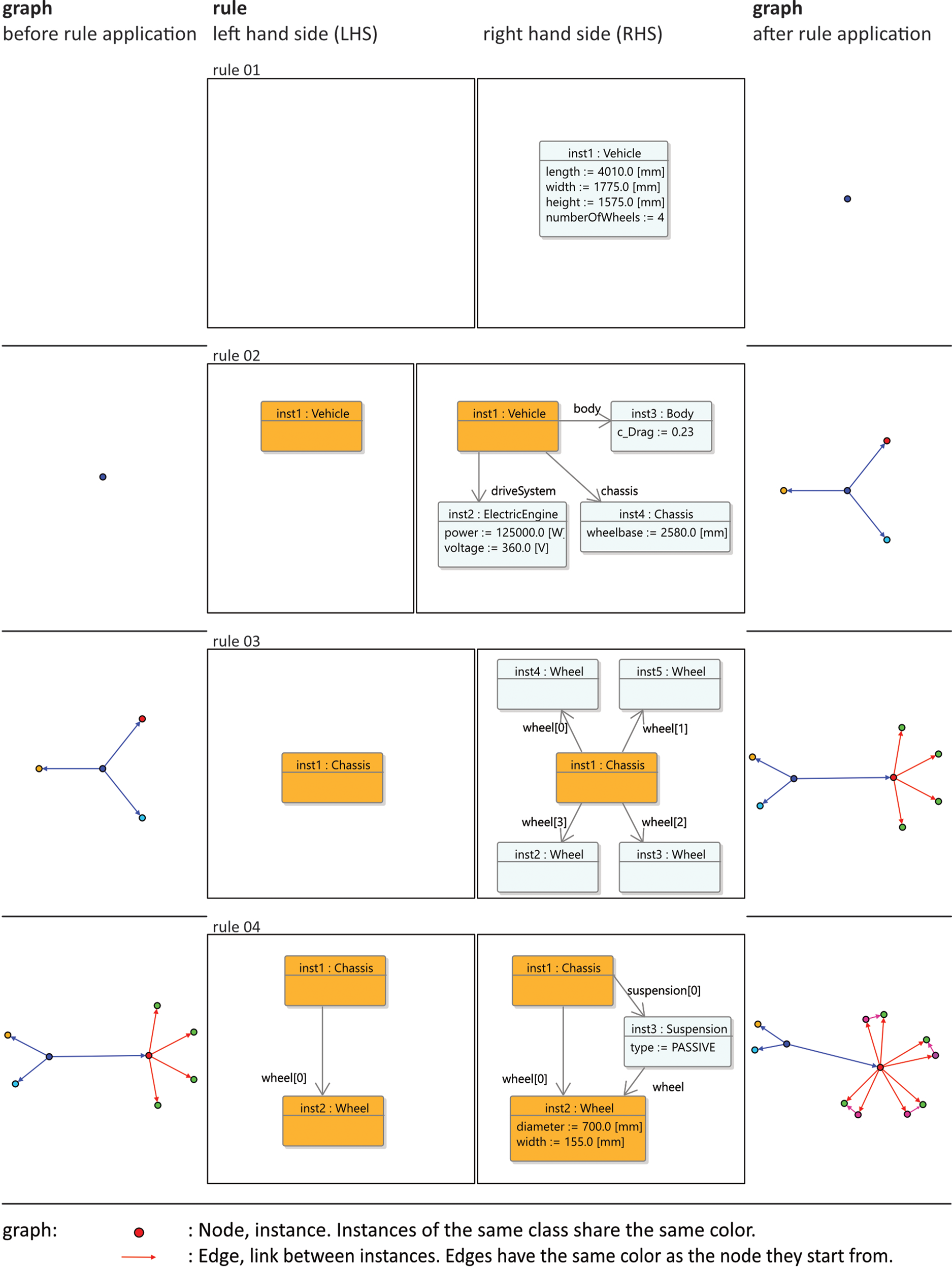
Fig. 3. Graph transformation described with the UML object diagram.
In Figure 3, the graph, representing the model of the vehicle, is depicted with nodes and edges. The UML object diagram can also be used to represent the graph. This view of the model is shown in Figure 4. Figure 4 shows the graph after the application of the rules depicted in Figure 3. In Figure 4, the links between the different instances as well as the parameters of the different attributes of the instances are shown.

Fig. 4. Graph representing finished model.
Discussion
Documenting the vocabulary and the rules is the first step to facilitate the application of graph transformation for engineering design in different software applications. This is due to the lack of a common, widely used language for defining the vocabulary and the rules. In the absence of an exchange standard, the reimplementation of the vocabulary and the rules in different software applications seems to be the approach that is currently more likely to be taken.
The documentation of the vocabulary and the rules should be clear and precise to reduce the likelihood of misunderstandings. Natural language or pictograms and symbols, that were created specifically for a particular design problem, are too ambiguous to serve as means for the documentation. For a precise documentation, a formalized notation should be used. The formal notation, that is used to document the vocabulary or the rules, can either be a graphical or a textual notation.
The documentation of the vocabulary can be carried out using a formally defined notation. For the appliaction of graph transformation for engineering design, the PROGRES graph schema as well as the UML class diagram are already in use (Zhang and Jiao, Reference Zhang and Jiao2013; Vogel and Arnold, Reference Vogel and Arnold2020). In the field of computer science, the UML class diagram has been used for this purpose (Hermann et al., Reference Hermann, Ehrig and Taentzer2008; Cabot et al., Reference Cabot, Clarisó, Guerra and de Lara2009). Using these notations to document the vocabulary could facilitate the exchange between different researchers and would allow to manually implement the vocabulary in different software applications. The use of a graphical notation seems to be especially promising. Graphical notations like the UML have been standardized and are widely used for software development. The UML class diagram may be used to model the relationships between the different elements of the vocabulary in a concise manner and provides a good overview over the vocabulary.
The documentation of the rules may not be as straightforward as the documentation of the vocabulary. For the simple example of the design of a vehicle, presented in this section, the use of a graphical notation is sufficient, but for more complicated cases, that involve application conditions for the rules, the use of a textual notation or a mixture of textual and graphical notation may be necessary. Graphical notations may be used to model application conditions, but this approach leads to large diagrams, that consist of several fields (Hermann et al., Reference Hermann, Ehrig and Taentzer2008). While the graphical representation of the rules may be more intuitive, it has been pointed out that the main criterion for the representation of the rules is the expressiveness of the notation, and concerning this criterion textual notations perform better (Jakumeit et al., Reference Jakumeit, Buchwald and Kroll2010). As a result, it is unlikely that the rules will be documented only by a graphical notation, since the documentation should be as expressive as the representation. One approach to deal with this issue is to present the code, that was used to define the rules as well as additional diagrams depicting the corresponding graphs (Königseder et al., Reference Königseder, Stanković and Shea2016; Vilgertshofer and Borrmann, Reference Vilgertshofer and Borrmann2017).
Depending on the size of the vocabulary and the number of rules, a complete documentation and subsequent publication can be a cumbersome task. For this reason, the creation of the documentation is ideally automated. For large implementations, the documentation of all the rules may exceed the scope of a research article.
Improved documentation of the production system
We suggest that formally defined notations should be used to document the vocabulary and the rules in research on the application of graph transformation for engineering design. If authors documenting their research find it necessary, these notations may be complemented by additional diagrams using pictograms or symbols. Depending on the complexity of the rules, different approaches may be necessary for the documentation of the vocabulary and the rules.
For the documentation of the vocabulary, a standardized graphical notation should be used. The examples in the reviewed literature show that the vocabulary can be documented using standardized graphical notations such as PROGRES or UML. If the vocabulary was defined using a textual notation, a standardized graphical notation, that supports the principles of object-orientation, such as UML or the Systems Modeling Language (SysML) should be used to document the vocabulary. The use of a graphical notation for the documentation of the vocabulary ensures that readers get a good overview of the different elements of the vocabulary.
Depending on the complexity of the rules, different documentation approaches may be necessary. A graphical notation is well suited for simple rules. For more complicated rules, the use of a graphical notation may not be sufficient or may produce large diagrams that consist of several fields and may be difficult to understand. In order to avoid this situation, the rules may also be documented using a textual notation.
Processing
In this section, three common approaches to the use of graph transformation for engineering design are presented. The classification of the existing research is done following the example by Blostein et al. (Reference Blostein, Fahmy and Grbavec1996), which distinguished implementations according to the organization of the graph transformation rules. We present features of the approaches and provide examples. In a subsequent step, advantages and disadvantages as well as the applicability of each approach are discussed.
There are different approaches using graph transformation for engineering design. For engineering design, graph transformation can be used on its own or as part of a larger process. If it is used without any other software applications, it is used directly to solve a certain engineering problem. Another approach is to use graph transformation as part of a larger process. In this case, graph transformation is used in combination with other components to solve a certain engineering problem. An example for this case is the use of graph transformation to create a design and the subsequent simulation of the potential solution using another software application. In both of these cases, different approaches can be implemented on how the rules are processed. In the following, three different approaches are presented.
Blostein et al. (Reference Blostein, Fahmy and Grbavec1996) distinguished implementations according to the organization of the graph transformation rules. Blostein et al. have distinguished between unordered graph rewriting, ordered graph rewriting, event-driven graph rewriting, and graph grammars. While the first three categories distinguish between the type of rule application, graph grammars refer to cases where a language is defined, although Blostein et al. have acknowledged that in practice the term grammar is sometimes used without regard to the language definition characteristic (Blostein et al., Reference Blostein, Fahmy and Grbavec1996). In the context of engineering design, it is not always clear if the term graph grammar is used according to this strict definition. For engineering design, the creation of all solutions may not necessarily be the goal. Often the goal is to find solutions that perform well in respect to certain requirements and can be found within an acceptable time frame. As a result, the category of graph grammar is omitted and only the organization of the rewrite rules is taken into account. Since the focus of the use of graph transformation for engineering design is on the automation of design processes, the use of external events such as user input to structure graph transformation is also not taken into account.
The used categories for the classification are unordered graph rewriting and two subcategories of ordered graph rewriting, partially ordered graph rewriting, and fully ordered graph rewriting. The categories follow the classification outlined by Blostein et al. (Reference Blostein, Fahmy and Grbavec1996). Following the classification outline by Blostein et al. (Reference Blostein, Fahmy and Grbavec1996), the categories used in this review exhibit the following characteristics. In unordered graph rewriting, the rules are not ordered and theoretically any applicable rule can be chosen to rewrite the graph. Partially ordered graph rewriting uses different methods to impose some order on the rewrite rules. To be considered as partially ordered in this review, the rewriting process may be divided into different phases, in which the rules are either unordered or partially ordered, probabilities may be assigned to each rule to influence rule selection, or special algorithms may be used to guide the rule-selection process. In fully ordered graph rewriting, the focus is less on the exploration of different results and more on the automation of the model creation. For fully ordered graph rewriting, the exact order of the rewrite rules is defined and rules are either applied once, or as many times as the search pattern is found, depending on the conventions of the software application used, or rules are not applied in case the search pattern is not found. Depending on how multiple occurrences of a search pattern are handled, additional control structures may be necessary to produce a deterministic result (Schürr et al., Reference Schürr, Winter and Zündorf1999). These categories are based on the work by Blostein et al. (Reference Blostein, Fahmy and Grbavec1996) and were chosen to fit the purpose of this review to examine the use of graph transformation in engineering design. This classification differs from the classification of different exploration approaches in probabilistic, tree-traversal, and rule-based agents that was given by Grasl and Economou (Reference Grasl and Economou2018). The classification based on graph rewriting was chosen to account for the different approaches examined in this review.
Unordered graph rewriting
In the case of unordered graph rewriting, the application of rules does not follow a predefined order. No order concerning the rule application is imposed by the designer of the graph transformation system or the graph grammar. In some cases, all possible solutions are created, while in other cases termination criteria, such as a certain performance of a valid design, the number of created solutions, or the elapsed time, are defined. Graph transformation can be part of a larger process to find a satisfying engineering solution. In this case, the process can have additional steps. If graph transformation is used as part of a larger process, graph transformation can be used to define the topology of a design solution, while the parameters of the instances are optimized in a separate step.
Examples
Unordered graph rewriting can be used to create all possible solutions defined by the vocabulary and the rules. Graph grammars are especially well suited for this case. An example for this approach is the graph grammar that is used to model technical processes (Stanković et al., Reference Stanković, Štorga, Shea and Marjanović2013). The grammar is used to enumerate all possible solutions for a stiffened panel assembly line (Stanković et al., Reference Stanković, Štorga, Shea and Marjanović2013).
The generation of all possible solutions is not always possible. If only some solutions need to be generated, the search needs to be constrained. The search can be understood as a search in a search tree, with a starting configuration of the graph as the root of the tree as depicted in Figure 5. For this reason, tree-search algorithms are often used to explore the search space. Breadth-first search is used in an example for the Network-Based Rule Analysis Method (Königseder et al., Reference Königseder, Stanković and Shea2016). This analysis method provides the designer with a better understanding of rule matches and allows detecting rules that slow down the search process, because they undo each other or lead to confluence (Königseder et al., Reference Königseder, Stanković and Shea2016). Dealing with confluence is especially important in order to provide an efficient search (Eichhoff and Roller, Reference Eichhoff and Roller2016). For this reason, the “dynamic rule independence analysis” was proposed by Eichhoff and Roller. Dynamic rule independence analysis can be used to reduce the number of operations and was tested with unordered and partially ordered graph rewriting (Eichhoff and Roller, Reference Eichhoff and Roller2016).

Fig. 5. Example of search in the search tree. Starting from an initial graph, many different solutions can be generated.
While tree-search algorithms are used to navigate the search space, custom algorithms are used to guide the search process towards promising solutions. Custom algorithms may be used when the search process involves several steps, for example including a step where the parameters of a design are optimized. The “topologic and parametric tune and prune” ((TP) $^{2}$) algorithm is an example for this approach (Patel and Campbell, Reference Patel and Campbell2010). In the presented research, (TP) $^{2}$ used a maximum number of iterations or a maximum elapsed time as termination criteria. The algorithm was tested for the design of sheet metal parts and outperformed genetic algorithms (Patel and Campbell, Reference Patel and Campbell2010).
The definition of the design problem influences the search strategy. Regions of the search tree that are too close to the root may not satisfy all the constraints of the design problem and after a certain depth is reached, it can be likely that the solutions do not perform well in terms of objective functions (Swantner and Campbell, Reference Swantner and Campbell2012). For this reason, a best-first search has been used to find solutions for the topology of gear trains by Swantner and Campbell. Other aspects of the design were solved in a subsequent optimization step (Swantner and Campbell, Reference Swantner and Campbell2012).
Graph transformation can also be used to modify the topology of an existing graph, instead of adding elements to the graph that have not been part of the graph. The modification of a user-defined start graph, by either removing elements, adding existing paths, or adding existing elements in series, has been investigated in order to find solutions where failure events are less likely to affect the system performance (Arlitt and Bossuyt, Reference Arlitt and Bossuyt2019). Arlitt and Bossuyt used a custom algorithm to guide the search process. According to Arlitt and Bossuyt, in each iteration of this algorithm, the best-performing solutions were selected using roulette wheel selection and a random rule is applied to all selected designs. The search ended when predefined performance criteria had been met (Arlitt and Bossuyt, Reference Arlitt and Bossuyt2019).
Discussion
The examples show that unordered graph rewriting can be used for engineering design. Depending on how the design process is defined, unordered graph rewriting can be used on its own (Stanković et al., Reference Stanković, Štorga, Shea and Marjanović2013) or as part of a larger design process (Patel and Campbell, Reference Patel and Campbell2010). The approach works well for cases where design topologies are explored. Here, graph transformation is used to define the topology of the design, while the parameters of the design are determined in a subsequent optimization step (Patel and Campbell, Reference Patel and Campbell2010; Swantner and Campbell, Reference Swantner and Campbell2012).
Confluence can be an issue, depending on the definition of the vocabulary and the design of the rules. Finding duplicate results should be avoided, in case the evaluation of the designs is computationally costly or the runtime of the program is too long. In this case, confluence needs to be addressed.
Partially ordered graph rewriting
Depending on the design problem, an approach using unordered graph rewriting can take too long to be processed or can produce many invalid solutions. For these cases, partially ordered graph rewriting may be used. In order to avoid rule applications that do not serve the overall design goal, at least some order of the rule application is established. Various approaches are possible. Rule sets can be used for design problems that consist of a sequence of different phases or steps. An example of such an approach is illustrated in Figure 6. Rule sets constrain the application of rules to rules from a certain set during the development of the design. The different rule sets are then used in consecutive order.

Fig. 6. Example of a search using different phases with different rule sets for each phase.
Another approach is to assign each rule a probability, according to which it will be used. This ensures that rules that are beneficial for a certain design goal are executed more often. Special algorithms can be used to choose which rules are applied. A combination of the approaches is also possible: for example using rule sets, where the selection of each rule has a certain probability. Graph transformation can be part of a larger process where subsequent steps to the application of graph transformation might involve the optimization or the evaluation of the created designs.
Examples
Rule sets can be used to structure the order in which rules are applied. If the design consists of different phases, each phase can have its own rule set. This is demonstrated with the design of a coffee grinder using GraphSynth (Kurtoglu et al., Reference Kurtoglu, Swantner and Campbell2010). Kurtoglu et al. present a design process, where in the first phase, the function structure for the design problem is created, then the configuration flow graph is created and finally components are selected. The first phase is further subdivided into three phases with separate rule sets, while the second and third phase each employ just one rule set (Kurtoglu et al., Reference Kurtoglu, Swantner and Campbell2010). Rule sets do not necessarily have to deal with design decisions. In order to determine the manufacturing operations for 3D solids, different kind of rule sets have been used: decision rule sets for alternative design decisions and rule sets used for pre- or postprocessing as well as asserting a certain state (Fu et al., Reference Fu, Eftekharian and Campbell2013).
Structuring the search into different phases enables a broad search in the beginning of the search process and a more narrow search for later phases. This is achieved by only selecting a certain percentage of solutions for later phases. This approach is used for the design of fluid channels (Hooshmand and Campbell, Reference Hooshmand and Campbell2014). In this work, the graph grammar is complemented by two consecutive steps, where the best candidates from the shape and topology generation are transformed from the graph to 3D shapes and evaluated in a computational fluid dynamics (CFD) evaluation (Hooshmand and Campbell, Reference Hooshmand and Campbell2014). A similar approach was used for the design of truss layouts (Hooshmand and Campbell, Reference Hooshmand and Campbell2016). Hooshmand and Campbell used a breadth-first search algorithm to create all valid topologies and transform the results from the graph to 3D shapes. To handle the creation of duplicate solutions, the application of confluent rules was prevented and the results were checked for duplicates (Hooshmand and Campbell, Reference Hooshmand and Campbell2016).
The order of rule application can also be influenced by assigning probabilities for each rule. Here, the difficulty lies in determining which probability should be assigned to which rule. For cases where no clear quality measure is defined, interactive user input can be used to evaluate the solutions and assign the probability of rule application accordingly in a subsequent step (Campbell et al., Reference Campbell, Rai and Kurtoglu2012). The assignment of probabilities for rule selection can be combined with rule sets. For the design of Palladian floor plans, probabilistic agents were used by Grasl and Economou to structure the sequence of rule application (Grasl and Economou, Reference Grasl and Economou2018). In this research, the probabilistic agents selected rules from different rule sets with an assigned probability for each rule within the set. Grasl and Economou suggest assigning the probability based on intuition or based on an analysis of the architectural work that is represented by the grammar (Grasl and Economou, Reference Grasl and Economou2018).
Special algorithms can also be used to guide the search strategy. The “Graph Heuristic Search” algorithm uses deep-learning to create a heuristic which is used to decide which rule application will lead to the best-performing candidates (Zhao et al., Reference Zhao, Xu, Konaković-Luković, Hughes, Spielberg, Rus and Matusik2020). For the design of robot structures, the “Graph Heuristic Search” algorithm performs better than a Monte Carlo Tree-Search algorithm and a random search algorithm (Zhao et al., Reference Zhao, Xu, Konaković-Luković, Hughes, Spielberg, Rus and Matusik2020).
Different search strategies for topologic and parametric rules have been explored, finding that the search strategy depends on the definition of the design task (Königseder and Shea, Reference Königseder and Shea2015). Königseder and Shea used the BURST algorithm in this research. Different search strategies should be used, depending on the sensitivity of the design task to the application of topologic rules (Königseder and Shea, Reference Königseder and Shea2015).
Discussion
Similar to unordered graph rewriting, partially ordered graph rewriting can be used to explore different design solutions. Partial ordering of the rules allows influencing the search process. Depending on the design problem, different approaches can be used to establish some kind of order for the rules. Rule sets are particularly fitting for design problems were the design process contains different stages. For cases where certain rules have a higher influence on finding a valid design than other rules, probabilities may be assigned for rule selection. In order to assign probabilities, either a heuristic function needs to be created or the probabilities need to be assigned manually. Whether the manual assignment of probabilities works better than a redesign of the rules or a reworked partial ordering of the rules in sets is unclear.
The use of special algorithms to guide the search process produces promising results. Since the use of a particular algorithm is problem-specific, the trade-off between the implementation of the algorithm and the runtime of the search should be considered. If the runtime of the search process is an issue, the search strategy should be chosen carefully. For these cases, confluence should also be addressed. Partially ordered graph rewriting can be used alone or as part of a larger design process. In this case, steps to evaluate or optimize the design are included in the search process.
Fully ordered graph rewriting
Compared with unordered or partially ordered graph rewriting, fully ordered graph rewriting takes a different approach. In fully ordered graph rewriting, the application of rules follows a predefined order. This approach allows to create a certain result for a certain input, as illustrated in Figure 7. The focus of this approach is less on the exploration of novel solutions and more on the automation of a process. Depending on the language and the environment, the application of a rule can be nondeterministic, if the graph contains multiple occurrences of the search pattern and the rule is randomly applied to one occurrence of the search pattern (Schürr et al., Reference Schürr, Winter and Zündorf1999). In this case, additional control structures may be used to ensure a deterministic behavior (Schürr et al., Reference Schürr, Winter and Zündorf1999).

Fig. 7. Example of changes to the graph using fully ordered graph rewriting.
This does not necessarily mean that this approach cannot be used to explore the design space. In order to explore the design space, the process simply needs to be started with different input parameters. Using fully ordered graph rewriting does not necessarily imply the use of only one linear sequence of rules. The description used for rule execution can involve loops and conditionals.
Examples
To describe the production process planning for product families, the language PROGRES is used (Zhang and Jiao, Reference Zhang and Jiao2013). In this research, the order of the rewriting rules is described using imperative control structures (Zhang and Jiao, Reference Zhang and Jiao2013). In some cases of design, the same result for a certain input is expected. This can be the case in the creation of architectural floor plans. For this reason, rule-based agents that exhibit deterministic behavior are used to generate designs that satisfy a set of requirements by using if-then rules (Grasl and Economou, Reference Grasl and Economou2018).
Graph-based design languages use rules that are presented in a predefined order. The transformation of the graph is either described by graphical rules consisting of a LHS and a RHS or procedural JAVA code (Vogel and Arnold, Reference Vogel and Arnold2020). Several design languages can be arranged in a hierarchy to model a system as a combination of subsystems, as shown with the example of satellite design (Gross and Rudolph, Reference Gross and Rudolph2016b). Through the change of initial requirements and executing the design language for each set of requirements, solutions that differ in topology as well as parameters can be explored, as shown with the example of 3444 different satellite layouts for different communications systems (Gross and Rudolph, Reference Gross and Rudolph2016c). The results are used to assess how different communication subsystems perform according to certain requirements in order to keep the overall system as light as possible, which is an important design factor in satellite design (Gross and Rudolph, Reference Gross and Rudolph2016c).
Discussion
With fully ordered graph rewriting, the focus is less on exploration of a design space and more on the automation of a particular design process. As a result, confluence is less of an issue. Even with this focus on the automation of the design process, the design space can still be explored. By restarting the design process with different input parameters, fully ordered graph rewriting can also be used as an exploratory tool, as the example for satellite design indicates (Gross and Rudolph, Reference Gross and Rudolph2016c). In this case, the focus of the search process is less on finding new topologies and more on getting a better understanding on how different elements of a system interact.
Future research directions
Previous sections presented a content analysis, different approaches to document the production system, and how different types of graph rewriting can be used for engineering design. In this section, future research directions for the application of graph transformation for engineering design are proposed. Apart from the reviewed literature, conference papers were also taken into consideration.
Better support of graph transformation in engineering design
In current practice of using graph transformation for engineering design, most practitioners define their own custom vocabulary for specific design problems. As a result, it is difficult to exchange implementations. Practitioners always need to familiarize themselves with the concepts used in a specific implementation. One way of addressing this challenge is to define common concepts once and reuse them for different problems. The "abstract geometry" can be seen as such an approach (Schmidt and Rudolph, Reference Schmidt and Rudolph2016). Similar approaches for continuum mechanics have been investigated (Vogel, Reference Vogel2018). Another approach is to use ontologies (Roelofs and Vos, Reference Roelofs and Vos2020).
The presented approaches probably need to be reworked or extended as they become more widely used. Theoretically, existing standards, libraries, or ontologies from other domains could also be used to define the vocabulary. Further research is necessary, to investigate how these standards, libraries, or ontologies can be adapted. It should also be investigated to which other domains beside geometry and physics the use of a common vocabulary can be applied.
This reuse is not limited to the vocabulary, but may contain design processes where graph transformation is used in combination with algorithms to solve domain specific tasks. A good example of this approach is the automated routing of system equipment for electrical wire harness design (Eheim et al., Reference Eheim, Kaiser and Weil2021) and the automated piping of landing gear (Neumaier et al., Reference Neumaier, Kranemann and Rudolph2021). Once the design process is defined, it may be reused in other contexts. Similar approaches may be implemented for other design processes.
Different approaches to guide the synthesis of new designs have been explored. Depending on the formulation of the design problem, certain strategies to guide the search process are more promising than others. One strategy to guide the search process is the use of different rule sets (Königseder and Shea, Reference Königseder and Shea2015; Puentes et al., Reference Puentes, Cagan and McComb2019). The synthesis of new designs may also be guided by the overall system reliability. Here, different strategies may be applied to increase the overall system reliability (Arlitt and Bossuyt, Reference Arlitt and Bossuyt2019; Riestenpatt gen. Richter and Rudolph, Reference Riestenpatt gen. Richter and Rudolph2019; Riestenpatt gen. Richter, Reference Riestenpatt gen. Richter2021).
Another approach is the use of different algorithms, such as (TP) $^{2}$ (Patel and Campbell, Reference Patel and Campbell2010), BURST (Königseder and Shea, Reference Königseder and Shea2015, Reference Königseder and Shea2016; Stöckli and Shea, Reference Stöckli and Shea2017), and Graph Heuristic Search (Zhao et al., Reference Zhao, Xu, Konaković-Luković, Hughes, Spielberg, Rus and Matusik2020). Depending on the formulation of the design problem, different algorithms are more effective than others (Patel and Campbell, Reference Patel and Campbell2010). For researchers or practitioners using graph transformation for engineering design, a comparison of the different algorithms, developed to guide the search process in engineering design, and the associated identification for which types of design problems the algorithms are suited, would be beneficial.
In the past, the lack of benchmark cases and criteria was identified as an obstacle for the evaluation of different software applications used for computational design synthesis (Chakrabarti et al., Reference Chakrabarti, Shea, Stone, Cagan, Campbell, Hernandez and Wood2011). In the context of graph transformation for engineering design, this is a persistent obstacle. Currently, there is little to no exchange of existing implementations between different software applications. Strengthening the exchange between different research groups by better documenting the vocabulary and the rules might be a good start to foster cooperation and lay the groundwork for the development of common criteria, which could be used to identify benchmark cases.
Product development process
Graph transformation in engineering design has been used in different domains and for different products in various stages of the product development process. The majority of the research falls in the domain of engineering, particularly mechanical engineering, and is situated in the conceptual design phase. Ideally, the application of graph transformation for engineering design should be extended beyond this phase. This could mean the extension of existing research to include a broader scope, or the application of graph transformation for engineering design in areas in which it has not been applied yet.
Existing examples should be extended towards multidisciplinary design. The example of satellite design shows that graph transformation can be used for multidisciplinary design (Gross and Rudolph, Reference Gross and Rudolph2016a). It should be examined how graph transformation for multidisciplinary design can be applied in other domains, including the field of architecture.
Another approach is to focus on particular fields for the application of graph transformation for engineering design. Two areas are especially promising: the beginning of the product development process and the end, when the product is manufactured. Requirements management has been explored for the development of gear systems (Holder et al., Reference Holder, Zech, Ramsaier, Stetter, Niedermeier, Rudolph and Till2017). The use of requirements has also been explored for the design of floor plans (Ślusarczyk, Reference Ślusarczyk2018). In practice, requirements are mostly defined as text. Existing approaches can detect redundancies in test specifications through formalization of the specifications (Walter et al., Reference Walter, Hammes, Piechotta and Rudolph2017). A similar approach could be used to incorporate requirements into design processes that use graph transformation. Further investigations in this area could facilitate the application of graph transformation in the industry. Graph transformation may also be used to enable individualized mass customization of products, as shown with the example of individual coffee maker designs (Tonhäuser and Rudolph, Reference Tonhäuser and Rudolph2017). Using the coffee maker design of Agarwal and Cagan (Reference Agarwal and Cagan1998) as a reference, graph-based design languages have been used to implement a generic design process for coffee makers that allows for the customization of individual designs by dedicated customer inputs for “lot-size 1” designs (Tonhäuser and Rudolph, Reference Tonhäuser and Rudolph2017).
The other end of the product development process should also be further explored. Once a product is designed, it needs to be manufactured. Graph transformation has already been applied to determine whether solid models can be manufactured (Fu et al., Reference Fu, Eftekharian and Campbell2013) and for defining lathe operations (Fu et al., Reference Fu, Eftekharian, Campbell and Kurtoglu2014). Graph transformation has been used for production process planning (Zhang and Jiao, Reference Zhang and Jiao2013). Further research needs to be conducted to include other production processes. An extension of the application of graph transformation to the digital factory is also possible.
Integration with existing processes
A better integration of the tools that use graph transformation into the design process is a continuing issue. This issue has been raised by Chakrabarti et al. (Reference Chakrabarti, Shea, Stone, Cagan, Campbell, Hernandez and Wood2011). In some cases, as in the shape grammar implementations that use graph transformation, the tools can be integrated into existing CAD software (Grasl and Economou, Reference Grasl and Economou2018). However, approaches that use graph transformation differ significantly from established CAD-centered approaches. In the field of geometry, it could be possible to bridge the gap between the approaches through the application of round-trip engineering (Schmidt and Rudolph, Reference Schmidt and Rudolph2016). This would make the transition easier for people trained to use CAD software.
For other approaches that are not centered on the geometry, graph transformation may be a natural fit. Currently, object-orientation is applied in the modeling of the vocabulary used for graph transformation. This lays the groundwork to use graph transformation in combination with MBSE to automate design processes. In MBSE, the V-model is used as a model to represent system development (Forsberg and Mooz, Reference Forsberg and Mooz1991; Graessler et al., Reference Graessler, Hentze and Bruckmann2018). An approach to enhance the MBSE development process with a machine-executable V-model has been outlined (Walter et al., Reference Walter, Kaiser and Rudolph2019). A key challenge will be the integration of the machine-executable V-model with existing MBSE processes and the adaptation and implementation of the approach for different products.
If graph transformation is used for engineering design, the vocabulary and the associated rules contain a significant amount of company knowledge (Eichhoff and Roller, Reference Eichhoff and Roller2016). One resulting challenge is how this knowledge can be protected from clients or competitors in collaborative design environments (Eichhoff and Roller, Reference Eichhoff and Roller2016; Vogel and Arnold, Reference Vogel and Arnold2020).
There are two challenges for the integration of graph transformation into design processes in engineering design. The first challenge is the need for a better integration of graph transformation in existing design processes. The second challenge is related to how engineers collaborate using graph transformation in engineering design. While an exchange between the different parties involved in an engineering project is wanted, the protection of the knowledge, codified in the vocabulary and the rules, can become an issue and needs to be addressed in future research.
Conclusion
In this article, different approaches to use graph transformation for engineering design have been presented. In total, 48 different journal articles that were published between 2010 and 2020 have been reviewed. The articles were analyzed for the content of the research. Two main research areas were identified: the development of new methods to use graph transformation for engineering design and the application of graph transformation for engineering design. Furthermore, it has been examined how production systems are documented. It was presented how different approaches to process the rules, unordered graph rewriting, partially ordered graph rewriting, and fully ordered graph rewriting can be used for engineering design. Based on the review of the examined journal articles, future research directions for the application of graph transformation for engineering design were identified. Graph transformation has been used for a wide array of different design problems in the research community. The next step will be to facilitate the application in the industry.
Financial support
The work of the first author was funded by the ZAFH research project “Digitaler Produklebenszyklus” (Digital Product Life Cycle), grant no. 43031423, see https://dip.rwu.de. The project is also supported by a grant from the European Regional Development Fund and the Ministry of Science, Research and the Arts of Baden-Württemberg, Germany. The funder had no role in study design, data collection and analysis, decision to publish, or preparation of the manuscript.
Conflict of interest
The authors declare none.
Christopher Voss is a PhD student at the Chair for Architectural Informatics at the Technical University of Munich. Currently, he is working in the research group Design Theory and Similarity Mechanics headed by Stephan Rudolph at the Institute of Aircraft Design at the University of Stuttgart. He received the degree of Dipl.-Ing. at the Faculty of Architecture at the University of Stuttgart. His current research focuses on the application of graph-based design languages in the AEC industry.
Frank Petzold heads the Chair of Architectural Informatics at the Technical University of Munich. He has a degree in computer science (Dipl.-Inf.) and holds a Dr.-Ing. in the field of Architectural Informatics from the faculty of architecture of the Bauhaus University Weimar. His research interests involve analyzing the activities of architects, formulating requirements for digital tools and – based on novel and future oriented technologies – creating concepts, developing and evaluating prototypical solutions. He previously held the position of junior professor of Architectural Informatics at the Bauhaus University Weimar. He is a founding member of the Association of Architectural Informatics in German-speaking regions and a member of the German Association of Computing in Civil Engineering, as well as various international bodies.
Stephan Rudolph obtained his Dipl.-Ing., Dr.-Ing., and Priv.-Doz. in Aerospace Engineering from the University of Stuttgart. He is Head of the Design Theory and Similarity Mechanics Group at the Institute of Aircraft Design at the University of Stuttgart, Germany. His broad research interests range from design theory over design languages and design compilers to artificial intelligence, similarity theory, and design and manufacturing automation in digital factory twins.


 Open access