


Introduction
Next-generation antennas will need to be characterized by a wideband behavior and by reconfigurability to generate multiple or scanning beams. To achieve these aims, several options have been proposed, and among them, the possibility to use reflectarray antennas (RAs) [Reference Huang and Encinar1, Reference Nayeri, Yang and Esherbeni2] has also been considered. Despite their copious advantages, RAs also present some drawbacks, the principal of which is a reduced bandwidth, essentially due to the intrinsic narrow bandwidth of single-layer printed elements, widely used for the realization of the RA unit cells (UCs) and to the frequency dependence of the path from the feed to the different points on the planar surface. To overcome this limitation, the use of elements with more degrees of freedom, printed on different layers, as in [Reference Encinar3, Reference Encinar and Zornoza4] or on the same dielectric substrate [Reference Chaharmir, Shaker and Legay5–Reference Kundu, Bhattacharya and Ruchi9], were introduced. Recently, the design of dielectric-only RAs is becoming popular, especially at mm-waves and sub-THz frequencies, where the metal losses are significant. Among the other potentialities, dielectric-only structures present a wider bandwidth and a low manufacturing cost that makes feasible the manufacturing of reradiating elements with arbitrary shapes. On the other hand, they are also responsible for some restrictions, related to the available materials, in most of the cases characterized by a low value of the relative dielectric constant and by high losses, to the printer resolution, that affects the minimum realizable size, and to the size of the printing plate.
Several examples of 3D-printed dielectric-only reflectarrays are available in literature. The configurations proposed in [Reference Zhang10, Reference Wu, Li, Zhou, Guo, Liu, Wei and Lv11] use dielectric parallelepiped resonators as UCs, whose height is varied to control the phase of the reradiated field. The 3D-printed prototype in [Reference Zhang10] has an aperture of  $12\lambda\times12\lambda$ and shows a 1-dB bandwidth of almost 10%, while that in [Reference Wu, Li, Zhou, Guo, Liu, Wei and Lv11] is characterized by a size of $20.5\lambda\times20.5\lambda$ at sub-THz frequencies and 1-dB bandwidth slightly lower than 21%. The configuration in [Reference Zhao, Wei, Li and Shi12] uses hemi-ellipsoidal dielectric resonators as reradiating elements: the designed antenna has an aperture size of $5.5\lambda\times5.5\lambda$ and 1-dB bandwidth of 11.2%. In [Reference Mei, Zhang and Pedersen13], a C-shaped dielectric UC with height approximately equal to 1.5λ is adopted for the design of a center-fed RA with diameter of 10λ. The 1-dB bandwidth in the case in which the radiated field is linearly polarized is slightly smaller than 12%. The reflectarray in [Reference Li, Mei, Zhou and Lv14] has an aperture of $11.2\lambda\times11.2\lambda$, discretized with cross-shape elements and provides a 1-dB bandwidth of 10.7%, while in [Reference Cui, Nauroze, Bahr and Tentzeris15], a Kirigami inspired two-stage snapping-like element is introduced for the realization of a $11.37\lambda\times11.37\lambda$ RA with a 1-dB bandwidth of 16.3%. Finally, the solution in [Reference Cheng, Hao, McGhee, Whittow, Cheng, Vardaxoglou, Mittra and Zhang16] adopts two orthogonal dielectric cuboids to design a $10.7\lambda\times10.7\lambda$ aperture that is able to generate a dual circularly polarized field over a 1-dB bandwidth ≈13%.
For what concerns the multi or scanning beam capability, the most straightforward solution is to design a reflectarray in which the behavior of the UC is controlled through active elements such as pin diodes [Reference Yu, Li, Su, Li, Xu and Yang17–Reference Wu, Lu, Wang, Jiang, Hong and Luk22], varactors, [Reference Li, Qi, Zhou, Xu and Denidni23–Reference Nam, Lee and Kim26], and MEMS switches [Reference Liu, Schmitt, Sievert, Lipka, Geng, Kolpatzeck, Erni, Rennings, Balzer, Hoffmann and Czylwik27] or using liquid crystal [Reference Kim, Kim and Oh28–Reference Zhang, Li and Zhang30] or liquid metal [Reference Carrasco, Gomez-Cruz, Serrano-Berrueco, Saavedra and Escobedo31] for its realization. All these choices strongly affect the complexity and the cost of the antenna, and therefore possible alternatives have been studied. If few projects, as the one in [Reference Zhang, Wu, Cheng, Chen, Yu and Fang32], are aimed to reduced the control points in the active reflecting surface, in other configurations, the RA is passive and the beam-steering is obtained by mechanically rolling the aperture [Reference Rubio, Kaddour and Georgakopoulos33] or more commonly moving mechanically the feed or using a feed array to change the direction of arrival of the field impinging on the reflecting surface [Reference Nayeri, Yang and Elsherbeni34–Reference Mei, Zhang and Pedersen36].
Despite its greater simplicity, such an antenna has some degradations of its radiation performance, as the enlargement of the main beam; an increase in the side-lobe level (SLL); a lowering of the maximum gain, which further decreases over the scan range; and a narrowing of the bandwidth. To improve the RA features, different techniques have been proposed, as that of designing a bifocal [Reference Nayeri, Yang and Elsherbeni37, Reference Cui, Bahr, Nauroze, Cheng, Almoneef and Tentzeris38] or a multi-focal [Reference Pirinoli, Lohrey, Orefice, Beccaria and Dassano39] reflectarray; in [Reference Pirinoli, Lohrey, Orefice, Beccaria and Dassano40], the RA is designed to behave as a quasi-spherical reflector, while in [Reference Wu, Qu, Yang and Chan41], the planar reflector is rotated in addition to the feed to cover a larger scan range. Finally, the results summarized in [Reference Nayeri, Yang and Elsherbeni37, Reference Niccolai, Beccaria, Zich, Massaccesi and Pirinoli42] prove that a pseudo-stochastic optimization algorithm can be fruitfully adopted to design a beam-scanning reflectarray with enhanced performance.
As for the bandwidth, the reflectarray beam-scanning capabilities also depend on the properties of the UC. In fact, its behavior is affected by the direction of arrival of the incident field, and hence when it changes, the UC generally does not provide the required phase compensation, and this results in a degradation of the antenna radiation properties. To reduce this effect, it is therefore useful to adopt a proper UC in addition to a suitable design procedure.
In this context, the possibility of using a UC alike the one introduced in [Reference Massaccesi, Beccaria and Pirinoli43] for the realization of a beam-steering RA is investigated. Some preliminary numerical results on the scanning beam behavior of an RA consisting of  $52\times52$ are already collected in [Reference Massaccesi, Beccaria and Pirinoli44], but the UC adopted there, as the one in [Reference Massaccesi, Beccaria and Pirinoli43], does not fulfil the constrains imposed by the Additive Manufacturing (AM) technique selected for the antenna realization even if the results in [Reference Massaccesi, Beccaria and Pirinoli43, Reference Massaccesi, Beccaria and Pirinoli44] confirm that the UC possess proper features for its use in the design of a scanning beam reflectarray with enhanced bandwidth. Here, the limitations introduced by the AM are taken into account and a printable version of the UC is defined, as is described in the section “Dielectric unit cell.” To verify its features and in particular its dependence from the angle of incidence, first, a single-focus RA is designed, and then its beam-steering capability is checked rotating the feed along an arc. In view of the encouraging numerical results summarized in subsection “Single focus RA: design and numerical analysis,” a bifocal RA is finally designed and manufactured. The numerical analysis and the experimental characterization of the prototype reported in the subsection “Bifocal RA: design, manufacturing, numerical and experimental characterization” show that the gain scan losses are lower than 0.8 dB over a scanning range of ±40∘, while the bandwidth varies between 13.5% and 28% over this interval.
Dielectric unit cell
The adopted UC is an optimized version of those introduced in [Reference Massaccesi, Beccaria and Pirinoli43, Reference Massaccesi, Beccaria and Pirinoli44]. As shown in the inset of Fig. 1, it consists in a dielectric parallelepiped with square basis, backed on a metallic ground plane, and having a square hole in the center, whose side d is varied to control the reflection coefficient S 11, while its height T is kept constant. The change of the hole size corresponds to modify the ratio between the quantity of dielectric material and air in the UC, resulting in a variation of its effective dielectric constant.
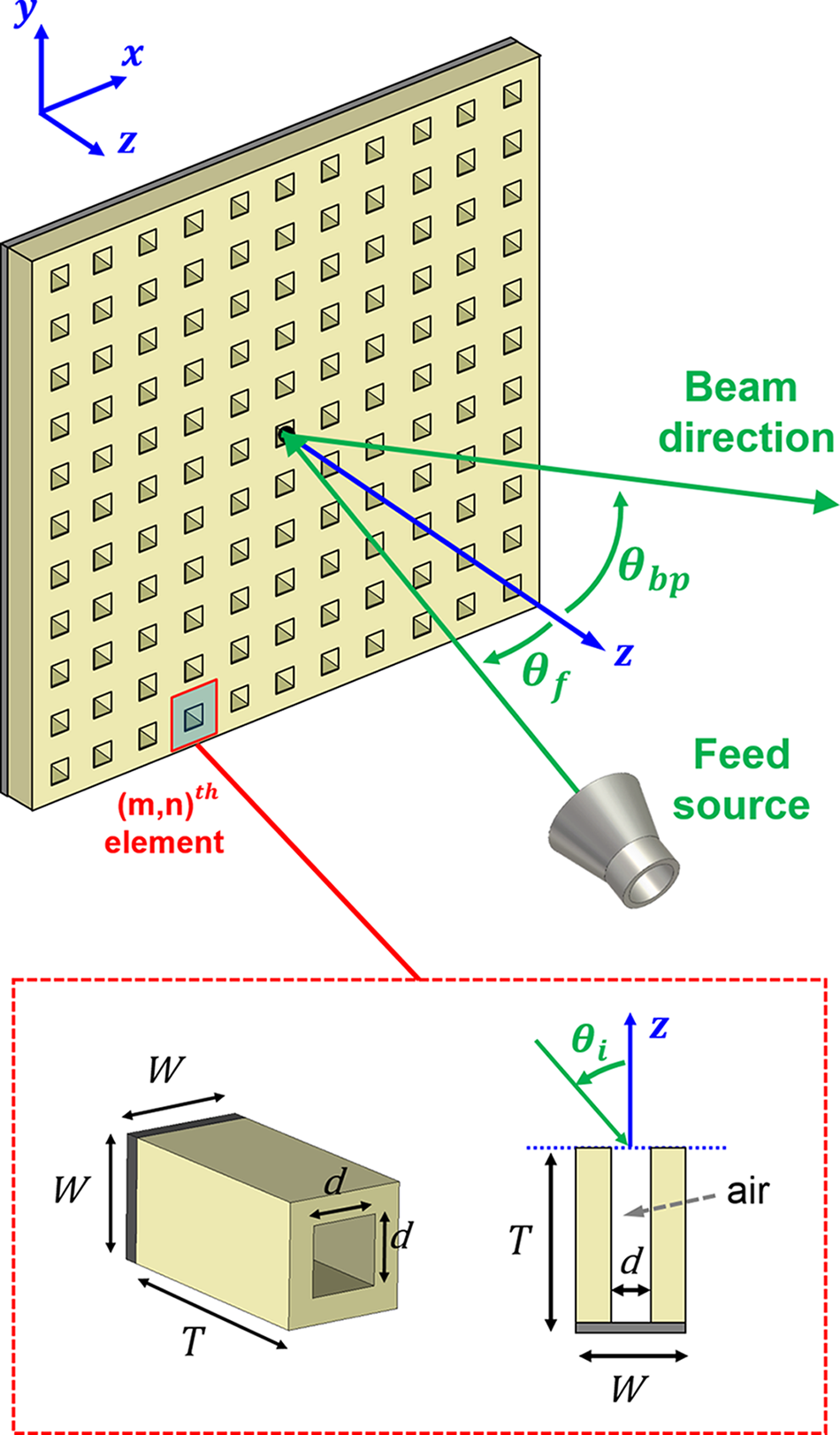
Figure 1. Sketch of the antenna configuration, with the UC in the inset.
To make possible the printing of the UC with an AM technique, and in particular with a PolyJet printer, a suitable dielectric material must be used. Here, the chosen material is the 3D-printable resin VeroWhitePlusTM provided by Stratasys® and characterized by  $\varepsilon_r = 2.77$ and $\tan\delta = 0.021$, which is the same used in [Reference Massaccesi, Pirinoli, Bertana, Scordo, Marasso, Cocuzza and Dasasano45, Reference Massaccesi, Dassano and Pirinoli46]. The UC has been designed in Ka-band at the operating frequency $f_0 = 30\,$GHz. Since the structures proposed in [Reference Massaccesi, Beccaria and Pirinoli43, Reference Massaccesi, Beccaria and Pirinoli44] were not suitable for 3D printing, a new version of the UC was optimized to maximize its performance while taking into account the limitations of the AM process. To determine the appropriate geometrical parameters for the UC that would allow for its fabrication, several test samples of dielectric sheets with square holes of varying sizes and heights were printed. After a thorough analysis, it was found that for small holes, the actual value of d was significantly smaller, and there was an increased risk of unwanted polymerization of small resin residues that could clog up the hole. In order to solve these issues, it was determined that the height of the UC should be maintained at a minimum of 6 mm and the size of the holes d should be varied within the range (0.8, 2.55) mm. This strategy aims to prevent systematic printing errors and to ensure that the holes are as accurate as possible. The optimal geometric parameters for the UC that satisfy the aforementioned requirements and maximize the performance are the following: $W = 0.3\lambda_0 = 3\,$mm, λ 0 being the wavelength evaluated at f 0, $T=0.8\lambda_0=8\,$mm, while d can vary between $0.8\,$mm and $2.55\,$mm. They are obtained following an optimization process organized in the three steps listed below.
(1) Choice of the size W of the UC: a smaller value guarantees a better sampling of the aperture and improves the antenna bandwidth but reduces the possible range of variation for the hole size d.
(2) Determination of the range of variation of the hole size d: if it is larger, the range of variation for the phase of the reflection coefficient is wider, but either too small or too large values for d must be avoided since they correspond to a UC that cannot be manufactured.
(3) Selection of T: increasing the height of the UC, it is possible to enlarge the range of variation for the phase of S 11, but at the cost of worsening of the losses introduced by the material and of a more bulky structure.
In Fig. 2, the frequency behavior of the amplitude (top) and phase (bottom) of the reflection coefficient is plotted for different values of the hole size. It can be noticed that the phase varies linearly over the entire frequency range and that its behavior is almost the same for all the considered values of d, as proved by the fact that the different lines are almost parallel; the amplitude of S 11 is never lower than −1.5 dB when  $d\geq2\,$mm, while its value decreases for smaller holes due to the increase of losses. The dependence of the reflection coefficient from frequency, and in particular the linear behavior of the phase, confirmS the wide band aptitude of the UC.

Figure 2. Unit cell: Variation of the simulated reflection coefficient S 11 with the frequency for different values of d. Top: amplitude. Bottom: phase. (UC dimensions:  $W=3\,$mm, $T=0.8\,$mm, $d=[0.8 , 2.55]$ mm).
Since the UC would be used for the design of a beam-steering RA, its dependence from the direction of arrival of the incident field is also studied. In Fig. 3, the variation of the amplitude (top) and phase (bottom) of S 11 is plotted with the angle of incidence θi, evaluated for different values of d at the design frequency f 0. As can be seen from these results,  $\angle S_{11}$ does not change significantly till $\theta_i = 40^\circ$, while the amplitude of the reflection coefficient behaves in a different way depending on the hole size. In particular, when it is small, $|S_{11}|$ reaches values even below −2.5 dB for $\theta_i \approx 30^\circ$. For larger d, the influence of the direction of arrival of the incident field is negligible, and this confirms the possibility to use the considered UC for the design of a beam-steering reflectarray.

Figure 3. Unit cell: Variation of the simulated reflection coefficient S 11 with the angle of incidence θi at 30 GHz for different values of d. Top: amplitude. Bottom: phase (UC dimensions:  $W=3\,$mm, $T=0.8\,$mm, $d=[0.8 , 2.55]$ mm).
Beam steering reflectarray
The UC previously discussed has been adopted for the design of two reflectarrays having the same configuration of the RA depicted in Fig. 1. Both the RAs have been designed with a side  $D=15.6\lambda_0$, corresponding to a discretization in 2704 reradiating elements. The aperture is illuminated by a 3D-printed smooth wall horn [Reference Beccaria, Addamo, Orefice, Peverini, Manfredi, Calignano, Virone and Pirinoli47], whose radiation pattern can be modeled as $\cos(\theta)^q$ with q = 12.5. The F distance between the phase center of the feed and the center of the planar aperture is 186 mm ( $F/D\sim1.2$). This value of F was chosen to optimize the illumination taper and the aperture efficiency of the reflectarray. Using this distance, the resulting edges taper is equal to −9.5 dB. The beam-scanning is obtained moving the feed in the vertical plane along a circular arc with radius F. A sketch of the antenna beam-scanning mechanism, with the information on the coordinate reference system, is shown in Fig. 4: referring to it, the vertical plane is the yz-plane, where the beam pointing direction θbp changes consequently to the rotation of the feed.

Figure 4. Beam-scanning reflectarray meachanism obtained moving the feed in the vertical plane along a circular arc with radius F for different scanning angles.
Single focus RA: design and numerical analysis
In order to check the scanning capabilities of the UC, first, a single focus reflectarray is designed to produce a pencil beam in the broadside direction when it is center-fed, which corresponds to the beam pointing angles ( $\theta_{\rm bp}=0^{\circ}$ and $\varphi_{\rm bp}=0^{\circ}$). The required phase distribution that produces this beam feature is shown in Fig. 5 and can be calculated as follows:

Figure 5. Required phase distribution of the 52×52 single focus RA. Mx and Ny refer to the number of elements in x and y directions, respectively.
 \begin{align}
\phi_{R}(x_m,y_n) = k_0(d_{mn} -(x_m\,\cos(\varphi_{bp}) + y_n\,\sin(\varphi_{bp}))\sin(\theta_{bp})),
\end{align}
\begin{align}
\phi_{R}(x_m,y_n) = k_0(d_{mn} -(x_m\,\cos(\varphi_{bp}) + y_n\,\sin(\varphi_{bp}))\sin(\theta_{bp})),
\end{align}where dmn is the distance from the phase center of the feed to each cell, while (xm,yn) represent the position of each element in the RA aperture. The design was carried out using only the phase curves obtained in the case of normal incidence. This assumption can be considered reliable due to the favorable behavior of the UC under oblique incidence, seen in the previous sections. The resulting RA is then numerically analyzed with CST Microwave Studio, not considering the position of the feed for which the reflecting surface is designed but moving the horn along the circular arc of radius F in such a way that θ bp varies between 10∘ and 40∘. A picture of the 3D CAD model of the single focus RA is shown in Fig. 6(a). Because of the symmetry of the structure, this corresponds also to cover the range of variation going from  $-40^\circ$ to $ -10^\circ$, so that a total scan range given by $[-40^\circ,-10^\circ]\cup[10^\circ,40^\circ]$ can be achieved. For sake of clearness, just the results related to the positive scanning range $[10^\circ,40^\circ]$ are plotted.

Figure 6. Three-dimensional (3D) CAD model of the two designed dielectric reflectarrays: (a) single focus and (b) bifocal.
The obtained radiation patterns in the vertical (E-) plane and for different pointing directions are plotted in Fig. 7, while the solid line curve in Fig. 8 represents the variation of the gain with the pointing direction for this RA. As expected, the radiation patterns and in particular the main beam degrade over the considered scanning range; however, moving the pointing direction from  $\theta_{\rm bp}= 10^\circ$ to $\theta_{\rm bp}= 30^\circ$, the gain decreases by only 1.1 dB. A more important degradation of the radiation performance can be noticed for the pattern pointing to $\theta_{\rm bp} = 40^\circ$ characterized by a gain loss of almost 3.5 dB and an enlargement of the main beam.

Figure 7. Simulated radiation patterns in the vertical plane for four different scanning angles, obtained through the numerical analysis of the single focus reflectarray.
In Fig. 9, the effect of the beam-steering on the bandwidth is shown; also in this case, the solid line curve refers to the single focus reflectarray, and it reveals that the 1-dB gain bandwidth is slightly lower than 19% for  $\theta_{\rm bp}=10^\circ$, while as it can be predicted by the behavior of the gain, it increases up to 38% for $\theta_{\rm bp}=40^\circ$.
The results on both the scanning performance and the bandwidth are promising, and suggest that the proposed UC is a potentially good candidate for designing reflectarrays with scanning beam capabilities and enhanced bandwidth with respect to other solutions.

Figure 8. Variation of the gain with the pointing direction. Solid line: simulated single focus RA; dashed line: simulated bifocal RA; and dash-dotted line: measured bifocal RA.

Figure 9. Variation of the 1-dB gain bandwidth with the pointing direction. Solid line: simulated single focus RA. Dashed line: simulated bifocal RA. Dash-dotted line: measured bifocal RA.
Bifocal RA: design, manufacturing, numerical, and experimental characterization
Since the analysis summarized above confirms the suitability of the UC, it is adopted for the design of a bifocal reflectarray that is expected to have improved scanning features with respect to the single focus configuration. In order to cover the same scan range considered in the subsection “Single focus RA: design and numerical analysis” and taking into account the structure symmetries, the bifocal RA is designed to provide the phase distribution  $\Phi_{mean}$ shown in Fig. 10 and obtained as:
 \begin{equation}
\Phi_{mean} = \frac{\Phi_1+\Phi_2}{2},
\end{equation}
\begin{equation}
\Phi_{mean} = \frac{\Phi_1+\Phi_2}{2},
\end{equation}where Φ1 and Φ2 are the phase distributions required to generate a collimated beam pointing to  $\theta_{\rm bp1} = -30^\circ$ and $\theta_{\rm bp2} = +30^\circ$, respectively. These distributions were obtained using Eq. 1 and using the phase curve related to normal incidence for both focal points.

Figure 10. Required phase distribution of the 52×52 bifocal RA. Mx and Ny refer to the number of elements in x and y directions, respectively.
The designed bifocal reflectarray has been simulated with CST MS and a picture of its 3D CAD model is shown in Fig. 6(b). A prototype of the reflectarray was manufactured using the Polyjet-based machine Objet30 (provided by Stratasys®) and then experimentally characterized. From the picture in Fig. 11(a), it appears that due to the required phase distribution and to the chosen additional reference phase, in the central part of the reflectarray, the UCs are characterized by smaller values of the holes, which increase going to the edges. This configuration is designed also in view of the results on the dependence from the incidence angle of the UC summarized in Fig. 3 and already discussed. Since the limitations introduced by the adopted 3D printer are taken into account in the UC design, none of the smaller holes results to be blocked. The holes set all around the RA surface are added for fixing it to the metallic ground plane through the use of a frame manufactured with FDM 3D printing technique. Figure 11(b) shows the entire antenna structure.

Figure 11. 3D-printed dielectric bifocal reflectarray with mechanical beam-steering: (a) prototype top view and (b) complete antenna structure.
In Fig. 12, both the simulated and the measured radiation patterns for different pointing directions at the design frequency are plotted. First, it is worth to note the very good agreement between the numerical and experimental results, confirmed by the performance summarized in Table 1. As expected, the radiation patterns of the bifocal RA are better than those of the single focus configuration, since they are characterized by a more constant gain over the entire scan range and consequently by a less remarkable enlargement of the beam width. As emerges from Table 1, both the numerical analysis and the measurements of the bifocal RA confirm that the HPBW changes less than 1 degree over the entire scan range, the SLL is always below −13.8 dB and the maximum gain scan loss is about 0.8 dB, as also shown by the dashed and dot-dashed line curves in Fig. 8, that are almost flat. As expected, the gain slightly reduces for pointing direction closer to broadside, which are farther from those considered for the design of the bifocal surface. Moreover, as typical of a bifocal configuration, the maximum gain is lower of almost 2 dB than the one of the single focus configuration, but this is the price to pay for keeping it more constant over the scan range. As expected, the gain reduction entails also a lowering of the aperture efficiency, that for the single focus configuration, when the pointing direction is that for which the antenna is designed, is of the order of 40%.

Figure 12. Radiation patterns in the vertical plane for four different pointing directions, obtained through the numerical analysis (solid line) and the measurement (dashed line) of the bifocal reflectarray.
Table 1. Summary of the simulated and measured bifocal RA performance for different pointing directions

For what concerns the 1-dB gain bandwidth, from Fig. 9, it appears that it is reduced with respect to that of the single focus configuration. Nevertheless, the results reported in the third row of Table 1 prove that it is slightly lower than 14% for  $\theta_{\rm bp} = 10^\circ$, but it increases in the other considered pointing directions. This is a remarkable achievement for a relatively large aperture, since larger structures are generally more challenging to design and analyze, requiring higher levels of accuracy and uniformity. This adds even more significance to the presented results compared to smaller structures typically reported in the literature.
Finally, in Table 2, the measured performance of the bifocal reflectarray is compared with those of other passive scanning beam RAs. Comparing the data relating to their size (row 3), it appears that the antenna proposed here has the largest aperture: this is to take into account discussing its radiating features, since it is well known that properties as the bandwidth decrease with the increasing of the aperture. For what concerns the scan range, only that covered by the RA in [Reference Wu, Qu and Yang35] is larger than the one considered here. The most remarkable performance of the designed reflectarray is the gain loss  $\Delta G$, equal to 0.8 dB over the entire scan range, significantly lower than the value obtained in [Reference Wu, Qu and Yang35] and comparable with the value reported in [Reference Nayeri, Yang and Elsherbeni37], which, however, refers to a smaller configuration and a narrower scan range. It is worth to notice that if the extremes of the variation interval for the pointing angle are reduced to $\pm30^\circ$, as considered in [Reference Nayeri, Yang and Elsherbeni37, Reference Cui, Bahr, Nauroze, Cheng, Almoneef and Tentzeris38], the measured gain scan loss provided by the reflectarray presented here is of the order of 0.2 dB only. The comparison among the maximum achieved 1-dB gain bandwidth confirms the good properties of the dielectric UC: as a matter of fact, the proposed RA and that in [Reference Cui, Bahr, Nauroze, Cheng, Almoneef and Tentzeris38] have a band that is significantly wider than the other two reported structures.
Table 2. Comparison between the measured features of the proposed passive bifocal beam-scanning RA and those of other similar configurations available in the literature

Conclusions
In this paper, a dielectric UC is used to design a reflectarray with favorable beam-steering capabilities and enhanced bandwidth. After having checked the performance of the UC, a bifocal reflectarray has been designed, manufactured with a 3D printer and experimentally characterized. The results confirm the RA’s good scanning capabilities, characterized by gain losses of the order of 0.8 dB over a  $\pm 40^{\circ}$ scan range, while the measured 1-dB bandwidth is attested to vary from 13% up to 28% over the entire scanning region. These results demonstrate the capability of 3D-printing technology for producing high-performance, cost-effective reflectarray antennas with wideband behavior and excellent beam-steering capabilities. Moreover, the proposed bifocal approach applied to a dielectric-only RA highlights the potential for a wide range of practical applications, from radars to wireless networking. A further improvement of this feature can be obtained adopting a proper optimization technique, like that used in [Reference Niccolai, Beccaria, Zich, Massaccesi and Pirinoli42], for the design of a beam-scanning reflectarray.

Andrea Massaccesi was born in Osimo, Italy, in 1987. He received the B.S. degree in electronic engineering from the Università Politecnica delle Marche, Ancona, Italy, in 2012, the M.S. degree in electronic engineering and the Ph.D. degree (cum laude) in electrical, electronic and communication engineering from the Politecnico di Torino, Turin, Italy, in 2015 and 2019, respectively. From November 2017 to May 2018, he was a visiting Ph.D. student with Loughborough University, Loughborough, UK, within the Symeta research program. Since January 2020, he has been a research fellow with the Department of Electronics and Telecommunications, Politecnico di Torino, Turin, Italy. His research activities include the study of underwater electromagnetic propagation and the design of proper antennas for underwater environments, the design and manufacturing of transmitarray and reflectarray antennas exploiting 3D-printing techniques, and the development of efficient global optimization techniques suitable for electromagnetic problems.

Michele Beccaria was born in Enna, Italy, on July 24, 1991. He received the B.Sc, the M.Sc. degree, and the Ph.D. degree (cum laude) in applied electromagnetics from the Politecnico di Torino in 2013, 2015, and 2019, respectively. He has been a research fellow with the Department of Electronics and Telecommunications, Politecnico di Torino, Turin, since January 2019 and has been an Assistant Professor since 2023. In 2017 and 2018, he was a visiting Ph.D. student with Tsinghua University, Beijing, China, under the supervision of Prof. Fan Yang. His research interests include reflectarray antennas, transmitarray antennas, smart electromagnetic surfaces, and the application of new optimization algorithms for complex antenna design. He was also recognized as the winner of two grants for attending the Ph.D. courses of ESoA in 2016 and in 2018 as one of the Best Ph.D. Students at Politecnico di Torino with the Ph.D. Quality Award. He was included in the Technical Committee of Conference of International Relevance (ICCE 2018, 2020) and serves many journals of the IET group as a reviewer. In 2020, he received the 2019 IEEE AP/ED/MTT North Italy Chapter Thesis Awards with the Best Ph.D. Thesis Antennas and Propagation Society for the thesis “Design of Innovative Reflectarray and Transmitarray Antennas.”

Valentina Bertana received her B.Sc. and M.Sc. Degree in biomedical engineering at Politecnico di Torino in 2013 and 2015, respectively. In February 2020, she received her Ph.D. degree at Politecnico di Torino in electrical, electronic and communication engineering. Her research activities are mainly focused on AM, smart materials, printable electronics, and microfluidics.

Simone Luigi Marasso received his Master degree in biomedical engineer and Ph.D. degree in electronic devices from Politecnico di Torino, Turin, Italy, in 2005 and 2010, respectively. From 2005 to 2011, he had a fellowship with Politecnico di Torino, Turin, Italy, and he worked at Chilab, materials and microsystem labratory at Chivasso, Italy. Since 2014, he is a CNR researcher, IMEM, @Politecnico di Torino DISAT department. His research activities focus on design and fabrication of MEMS, Lab on Chip and microfluidic devices as demonstrated by his scientific publications in these fields.

Matteo Cocuzza obtained the degree in electronic engineering at the Polytechnic of Turin in 1997 and the PhD in electronic devices in 2003. He is currently Associate Professor at the Department of Applied Science and Technology of the Polytechnic of Turin and associate researcher of IMEM-CNR. In 1998, he was one of the founders of the Chilab-Materials and Microsystems Laboratory and recently the co-founder of the new technological facility PiQuET – Piedmont Quantum Enabling Technologies. He is currently lecturer of master’s degree courses in the field of micro- and nanotechnologies, microsensors, MEMS, also in the context of the international master in nanotechnology for ICT (joint master between Politecnico di Torino, INPG Grenoble and EPFL Lausanne). His research activity is focused on the development of MEMS and microsensors for industrial applications, on the development of microfluidics and lab-on-a-chip for biomedical applications, and more recently, on the development and application of 3D printing polymeric technologies.
Gianluca Dassano received the Laurea degree in electronic engineering from the Politecnico di Torino, Italy, in 1999. Since 1999, he has been with the Department of Electronics and Telecommunications, Politecnico di Torino, as a Technician with the Electromagnetic Group, with particular interest in antenna application. At present, his main activities concern antenna prototyping and characterization inside the Laboratory of Antennas and EMC.

Paola Pirinoli received the M.S. (Laurea) and Ph.D. (Dottorato di Ricerca) degrees in electronic engineering from the Politecnico di Torino, Italy, in 1989 and 1993, respectively. From 1994 to 2003, she was an Assistant Professor (Ricercatore) of electromagnetic fields with the Department of Electronics and Telecommunications, Politecnico di Torino, where she was an Associate Professor from 2003 to 2018 and has been a Full Professor since 2018. From 1996 to 1997, she was a Visiting Research Fellow with the University of Nice, Sophia Antipolis, France. In 2014, 2015, and 2017, she was a Visiting Research Fellow with Tsinghua University, Beijing, China. She has coauthored around 250 journal articles and conference papers. Her main research activities include the development of analytically based numerical techniques, essentially devoted to the fast and accurate analysis of printed structures on planar or curved substrates, the modeling of nonconventional substrates, as chiral and anisotropic ones, the development of innovative and efficient global optimization techniques, and the design of innovative reflectarray and transmitarray antennas. In 1998, she received the URSI Young Scientist Award and the Barzilai Prize for the Best Paper at the National Italian Congress of Electromagnetic (XII RiNEm). In 2000, she was the recipient of the Prize for the Best Oral Paper on Antennas at the Millennium Conference on Antennas and Propagation. She serves as a reviewer for several international journals and conferences. She is a member of the TPC and the organizing committee of several international conferences.


