


1. Introduction
Hot-water drilling has long been used to study glaciers, ice sheets and ice shelves, providing a means to determine ice structure, debris content and hydrological features, as well as ice thickness if the bed is reached. Such boreholes allow direct access to the ice-bed interface, from which sediment and water can be sampled. Boreholes can also be instrumented to provide time-series records of ice characteristics, including ice temperature and deformation, and hydrological properties such as subglacial water pressure, electrical conductivity and turbidity. While other techniques such as mechanical coring (e.g. Árnason and others, Reference Árnason, Björnsson and Theodórsson1974; Zagorodnov and others, Reference Zagorodnov, Thompson, Ginot and Mikhalenko2005; Gibson and others, Reference Gibson, Johnson, Shturmakov, Mortensen and Goetz2014), steam drilling (e.g. Howorka, Reference Howorka1965; Gillet, Reference Gillet1975; Heucke, Reference Heucke1999) and thermal devices (e.g. Gillet, Reference Gillet1975; Mae and others, Reference Mae, Wushiki, Ageta and Higuchi1975; Schwikowski and others, Reference Schwikowski, Jenk, Stampfli and Stampfli2014) have been used in the past, hot-water drilling is often favoured because of its logistical ease, effectiveness and rapidity. Hence, the technique has been applied successfully in many locations, such as on numerous valley glaciers (e.g. Aamot, Reference Aamot1968; Hubbard and others, Reference Hubbard, Sharp, Willis, Nielsen and Smart1995; Eisen and others, Reference Eisen, Bauder, Lüthi, Riesen and Funk2009), the Greenland Ice Sheet (e.g. Iken and others, Reference Iken, Echelmeyer, Harrison and Funk1993; Ryser and others, Reference Ryser2013; Doyle and others, Reference Doyle2018), Antarctic ice streams (e.g. Engelhardt and others, Reference Engelhardt, Humphrey and Kamb1990) and ice shelves (e.g. Hubbard and others, Reference Hubbard2016; Ashmore and others, Reference Ashmore2017), and on surge-type glaciers, including in Alaska (e.g. Kamb and others, Reference Kamb1994) and Svalbard (e.g. Porter and Murray, Reference Porter and Murray2001; Kulessa and Murray, Reference Kulessa and Murray2003; How and others, Reference How2017). However, to our knowledge, hot-water drilling beyond a few metres depth has not been reported on any high-elevation debris-covered glacier.
Worldwide, very few high-elevation debris-covered glaciers are accessible by road, necessitating field teams to hike in (also necessary for physiological acclimatisation) and equipment to be transported by porter or animal. However, field equipment is often too heavy for transport by these means, leaving helicopters as the only, more expensive, option. A further complication is the reduction of helicopter payloads with elevation, introducing significant weight restrictions for individual items of equipment. Atmospheric conditions at high elevations additionally affect the drilling process, with reduced oxygen restricting combustion and limiting the heat and pressure outputs necessary for effective hot-water drilling. Once on a glacier, finding a suitable drill site can present further problems as the surface topography is often complex and difficult to navigate (e.g. Iwata and others, Reference Iwata, Watanabe and Fushimi1980), and access to a clean ice surface is limited by the highly variable debris layer thickness (McCarthy and others, Reference McCarthy, Pritchard, Willis and King2017). Hot-water drilling also requires a ready supply of water that can be siphoned or pumped from supraglacial streams and ponds. However, supraglacial ponds on high-elevation debris-covered glaciers are often ephemeral (Miles and others, Reference Miles, Willis, Arnold, Steiner and Pellicciotti2017) or frozen for much of the year, and can be difficult to access. Finally, viable drilling sites may be further restricted by hazards such as rockfall or avalanches from nearby mountain slopes.
Given these challenges, it is not surprising that hot-water drilling has rarely, if ever, been attempted at high-elevation debris-covered glaciers, resulting in a paucity of field-based data relating to the englacial and subglacial conditions at such glaciers. For example, ice thicknesses, bed topographies and basal conditions are commonly assumed or estimated from modelling (Bolch and others, Reference Bolch2012; Huss and Farinotti, Reference Huss and Farinotti2012; Rowan and others, Reference Rowan, Egholm, Quincey and Glasser2015), while measurements of ice temperature and thermal regime are also extremely limited (e.g. Mae, Reference Mae1976; Zhang and others, Reference Zhang2013). To our knowledge, no direct measurements exist for either englacial debris content or dynamic regimes (i.e. rates and styles of ice movement by basal sliding and/or deformation) at such glaciers. As a result, dynamic models of Himalayan glaciers are missing crucial field data for model calibration and validation, which are needed to make robust predictions of future glacier geometric change and contributions to river discharge, water resources and ultimately sea level (Rowan and others, Reference Rowan, Egholm, Quincey and Glasser2015).
Here, we present our apparatus, method and experiences of hot-water drilling on the high-elevation debris-covered Khumbu Glacier, Nepal Himalaya, in 2017 and 2018. The aim of the parent research project (‘EverDrill’) was to characterise the englacial structure and temperature, basal dynamics and hydrology of Khumbu Glacier by using hot-water drilling to access the glacier's interior and/or bed at multiple locations. We discuss the methods developed to address this aim, from specific equipment and adaptations to on-the-ground site selection and preparation. We then evaluate: (i) the strengths and limitations of our approach, including system performance over the course of two field seasons; (ii) the nature of the boreholes that were drilled and (iii) the difficulties of site selection for subsequent data collection. Finally, we suggest adaptations to the equipment and method to facilitate future hot-water drilling at high-elevation debris-covered glaciers, both at similar and higher elevations to those at which we drilled on Khumbu Glacier.
2. Equipment and methods
2.1. Combustion engine power loss at high elevation
The efficiency and power output of internal combustion engines decreases with reduced oxygen at high elevations. Specifically, combustion is adversely influenced by both the absolute decrease in oxygen available, decreasing the heat that expands each charge of air, and lower air density reducing the mass of air available for that expansion. Consequently, engine output typically decreases by ~1.2% for each 100 m increase in elevation (Fig. 1). Thus, for operation at ~5000 m above sea level (a.s.l.) on Khumbu Glacier, a combustion engine is projected to generate only ~55% of its rated power at sea level (Honda Power Equipment, 2018). This severe reduction in power output is estimated for an ideal mixture of air to fuel; real carburetion conditions would result in a further reduction of power output. We compensated, to some extent, for this loss of engine power by: (i) using larger engines than would be required for the same power output at sea level, and (ii) ‘rejetting’ all engines' carburettors. Rejetting involves reducing the fuel supply to match, as closely as possible, the oxygen supply and air density at the anticipated elevation (thereby achieving the most complete combustion feasible) by using a smaller diameter fuel nozzle. However, because no perfect solution was available for efficient operation at 5000 m a.s.l. without substantial engine redesign, both incomplete combustion and sub-optimal operation were still anticipated. These issues included, for example, the reciprocating piston decelerating under lower force during compression and exhaust cycles (caused by the lower air mass in the chamber) than is ideal. The 2017 EverDrill field season was therefore partially viewed as an equipment trial, designed to inform equipment and operational choices for the 2018 field season. The elements of our equipment set-up, subject to these influences, are considered individually in their respective sections below.
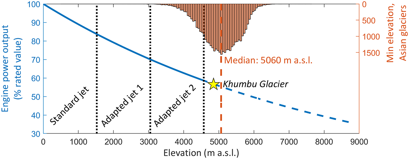
Fig. 1. Estimated reduction in power output for a naturally-aspirated combustion engine (such as used to drive the pumps in this study) due to reduced oxygen and pressure at high elevations, assuming perfect carburetion (blue line). Honda recommends smaller fuel nozzles to maintain fuel–air mixtures in the appropriate range (Honda Power Equipment, 2018) (‘rejetting’; vertical dotted lines), but no recommendation is made for beyond 4500 m a.s.l. (dashed blue line): fuel–air mixtures will thus become too fuel-rich above this elevation, further affecting power. The figure also indicates the distribution of minimum glacier elevations across High Mountain Asia from the Randolph Glacier Inventory 6.0 (RGI Consortium, 2017) (brown vertical bars), and the expected reduction in power at the elevation of the terminus of Khumbu Glacier (yellow star).
2.2. Equipment
Figure 2 shows a typical drilling set-up from one of our sites in 2018 (Figs 2a, b), with particular aspects shown in the lower panels (Figs 2c to e).
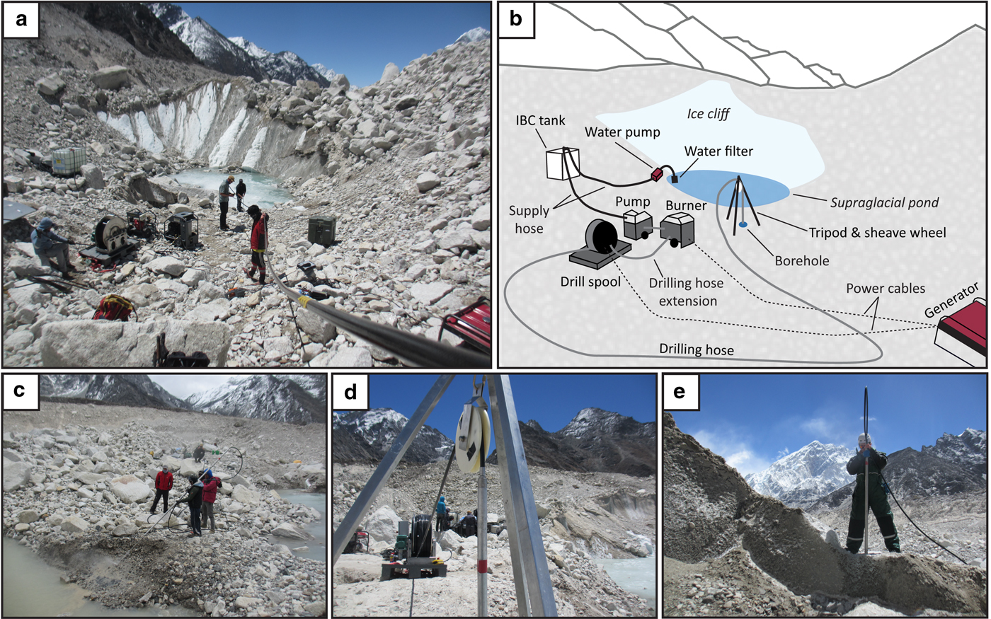
Fig. 2. Images of a typical drilling set-up and preparations before drilling. (a) Equipment set-up at Site 4 in 2018; components are shown in a schematic illustration of this image in (b) which includes examples of some additional equipment. Drilling preparations are shown in lower panels: (c) after manual removal of coarse surface debris, fine debris was cleared as part of final equipment testing (Site 5, 2018); (d) drill stems and drill hose hanging over the tripod and sheave wheel, fed directly from the drill spool, to begin drilling (Site 1, 2017); (e) drilling begun manually without using the tripod and sheave wheel due to uneven and unstable terrain (Site 5, 2018). Site locations are shown in Figure 3.
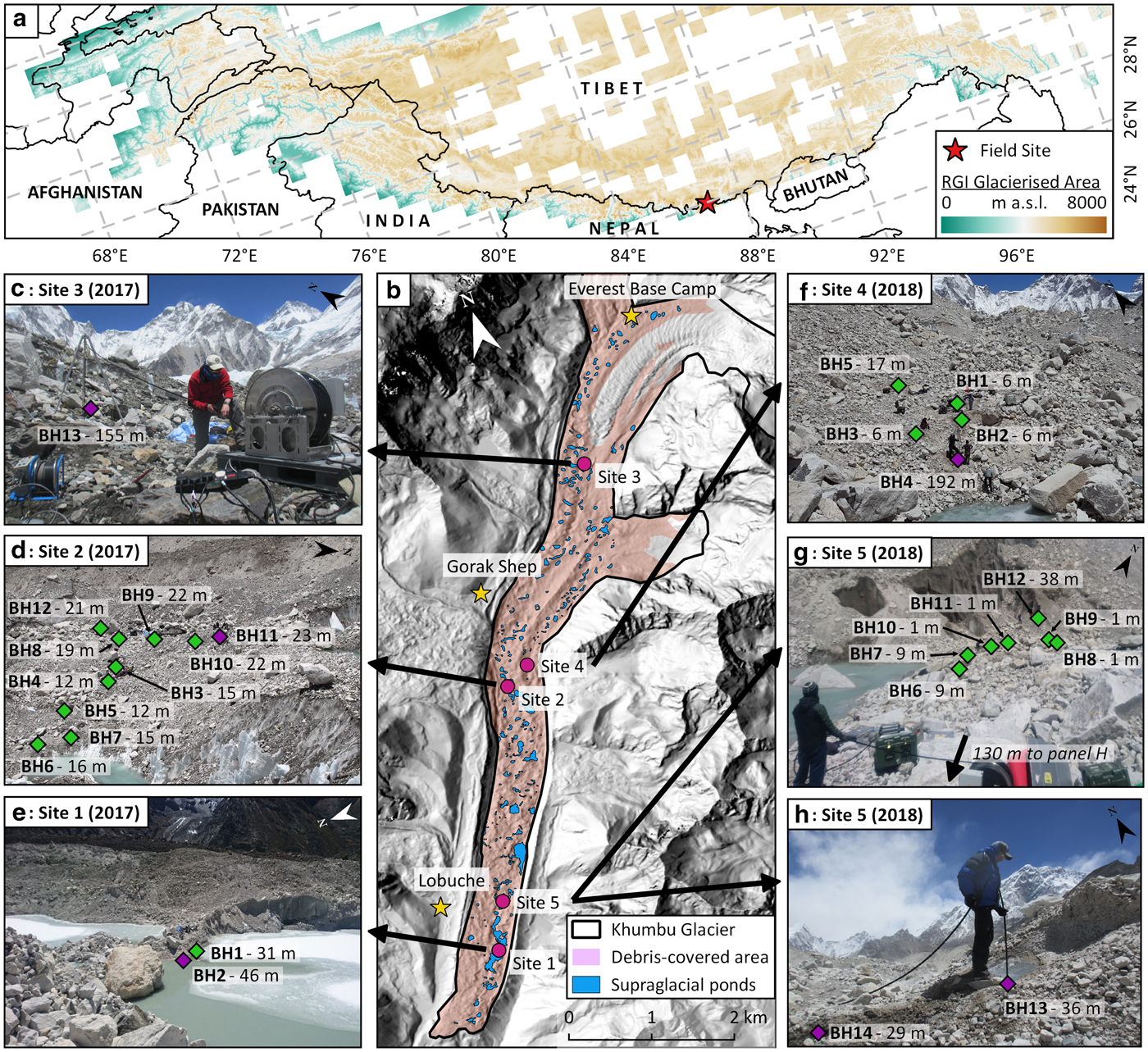
Fig. 3. Location of Khumbu Glacier, Nepal (a), and of our drill sites on the glacier (b). Borehole (BH) IDs and their lengths are shown by diamond markers (green = not instrumented; purple = instrumented; Table 1, Section 3.3) on an image of each drill site (c–h). Elevation in (a) is shown using the 2010 GMTED DEM (Danielson and Gesch, Reference Danielson and Gesch2008) within glacierised areas using a tiled mask from the Randolph Glacier Inventory 6.0 (RGI Consortium, 2017). Background in (b) is a hillshade created from the HiMAT mosaic DEM (Shean, Reference Shean2017). People are present in each image for scale: in (d) above BH11; in (e) above BH1 and in (g) to the left of BH12. Boreholes in this figure are numbered by year, with the year denoted in each subpanel header.
Table 1. Information regarding all boreholes drilled on Khumbu Glacier, Nepal, in 2017 and 2018 as part of the EverDrill project

*Our borehole naming convention (e.g. BH17-01) consists of the year drilled, followed by the borehole number (for that year). $Local time zone is Nepal Standard Time (NPT; UTC + 05:45). &Borehole sensors are described in Section 3.3 and ^borehole logging by an optical televiewer (OPTV) in Section 3.2.2.
2.2.1. Low-pressure water transfer
To obtain and store water to begin hot-water drilling, a Honda WX10 (petrol) water pump was used to drive ~15 L of water per minute from a supraglacial pond to a 1000 L intermediate bulk container (IBC) tank (Figs 2a, b). The WX10, along with all other combustion motors used in the project, was rejetted using the smallest jet available prior to the field season (Section 2.1). The WX10 drew in water via a single 15 m length of 1 in-diameter ribbed supply hose, with a foot valve/filter on the pond end to exclude larger debris clasts (Fig. 2b). The pump was connected, using a single 50 m length of similar supply hose, to the IBC tank, which provided a temporary water store and a settling well for finer sediment. The IBC tank was located at least ~1 m above the high-pressure pump (Section 2.2.2) to produce a constant pressure head and thus deliver a slightly pressurised water supply. This supply was transferred using a further 15 m length of supply hose, again with a foot filter on the source end in the IBC tank to ensure no debris particles could enter the pump and pass through the system (potentially wearing the pump and blocking the terminal nozzle). In practice, the IBC tank and high-pressure pump were located within a few metres of each other for convenience (Figs 2a, b).
2.2.2. Pressurisation and heating
In 2017, a Kärcher HDS 801 B combined pump and burner unit, weighing ~106 kg, was used to heat and pressurise water. This unit uses a Honda GX160 petrol-driven engine (3.6 kW power output at sea level) to both pressurise water and drive the fan and fuel pump of the integrated diesel heater.
In 2018, to address limitations that became apparent during the 2017 field season (Section 3.1.3), a separate petrol-driven pump (Kärcher HD 9/23 G; ~76 kg), and diesel burner (HG 43; ~88 kg) were used (Figs 2a, b). Separating the pump from the burner provided greater transport flexibility and increased the system's power, with the HD 9/23 G incorporating a Honda GX390 engine (providing 8.7 kW power output at sea level – reducing to an estimated 4.5 kW at 5000 m a.s.l.). Both the HD 9/23 G and the HG 43 were armoured by the addition of steel base panels and braced with tubing to improve durability for the rough terrain and potential damage during transport. System performance was monitored live by the addition of gauges displaying the pressure of water leaving the pump and the temperature of water leaving the burner.
2.2.3. High-pressure water transfer
The heated, pressurised water was transferred from the Kärcher unit(s) to a drill spool via ~15 m of high-pressure hose. For EverDrill, we used ½ in bore thermoplastic hose (Polyhose (UK) Ltd; EF148-R7), with a nominal working pressure of 140 bar, a minimum burst pressure of 560 bar and an outside diameter of 19.3 mm. The drill spool held a further 200 m of coiled high-pressure drilling hose of identical specification (Figs 2a, b). The length of hose on the spool was determined by helicopter weight restrictions and the maximum anticipated borehole length (Section 2.3.1).
The spool and hose combined comprised the heaviest single item, weighing ~150 kg. An integrated electric motor turned the spool to release hose at a user-controlled rate (Section 2.3.3). The spool motor was powered by a Honda EG5000CX (petrol) generator, with a smaller Honda EU20i (petrol) generator providing back-up and occasional additional use. Both generators were rejetted and ran mostly successfully at elevations of ~5000 m a.s.l. (Section 3.1.2), with the larger EG5000CX operating more smoothly.
Two stainless-steel drill stems (each 1.5 m length and ~10 kg weight), joined to make a single 3 m-long stem, were attached to the end of the main hose to provide weight and aid borehole verticality. All connections were ½ in British Standard Pipe (BSP) parallel with additional quick-release connectors where appropriate. A tripod and sheave wheel were used to hang the drill hose and stems directly above the borehole (Fig. 2d). A high-pressure nozzle with a ¼ in BSP parallel outside thread (PNR UK Ltd) was attached via a ¼ to ½ in bush to the base of the drill stem. Nozzle diameter determines the pressure of the water jet supplied to the melting front, with smaller diameter nozzles producing greater pressure but requiring more power from the pump. Given the vagaries of engine operation, field deployment and ice conditions, a broad selection of nozzles was made available to choose from in the field.
2.3. Methods
2.3.1. Site selection
The selection of a general area (10 × 10 m) for a drill site on Khumbu Glacier involved combining considerations of safety, research aims, methods and logistics. Through the two field seasons, five sites were identified (Sites 1–3 in 2017, and Sites 4–5 in 2018; Fig. 3) to provide spatial coverage of the glaciological and hydrological properties targeted by EverDrill. Based on radar surveys of ice thickness (Gades and others, Reference Gades, Conway, Nereson, Naito, Kadota, Nakawo, Raymond and Fountain2000), Sites 1 and 5 were designed to have the best chance of reaching the glacier bed, being near the terminus where the ice is thinnest. The location of Site 2, approximately in the centre of the ablation area, was selected to measure ice properties in this region. Site 2 boreholes were also drilled with the hope of reaching the bed (~200 m depth (Gades and others, Reference Gades, Conway, Nereson, Naito, Kadota, Nakawo, Raymond and Fountain2000)), but additionally to intersect part of the drainage system, being located a short distance downglacier from a large tributary glacier stream input to the bed of Khumbu (Miles and others, Reference Miles2019). When none of the Site 2 boreholes reached the bed (Section 3.2.3), Site 4 was located nearby, but on the far (east) side of the glacier with the intention of drilling a longer borehole. Finally, Site 3 was designed to record ice properties in the upper ablation area to the greatest depth possible (in the knowledge that our 200 m hose length would be insufficient to reach the bed (Gades and others, Reference Gades, Conway, Nereson, Naito, Kadota, Nakawo, Raymond and Fountain2000)).
Once the general drill site region was identified, a specific site (1 × 1 m) was chosen based on local factors. Most importantly, access to a clean ice surface was required. Thinner debris cover (≲200 mm, thus removable by hand/ice axe) is often found on steep surface slopes and around supraglacial pond margins. Sites also needed to be located near to a continuous surface water supply, ideally ponded so that sediment was settled out of suspension. The lateral and vertical distance from such a pond was limited by the power of the water pump to transport water to the IBC tank (Sections 2.2.1 and 3.1.2). Yet, where possible, boreholes were located as far as practicable (both horizontally and vertically) from the supply pond for both safety reasons and to reduce the potential of inundation by pond expansion during the subsequent monsoon season (Sections 3.3).
2.3.2. Preparation
Following site selection, equipment was transported by porter or helicopter sling to within some metres of the proposed borehole location. Approximately one day at each site was required to level areas for equipment placement. Reduced helicopter lift at ~5000 m a.s.l. limited sling loads to ~170 kg, while safe manual repositioning across the debris surface limited most items to <100 kg. Our total system weighed ~1000 kg, which took four to five helicopter trips per site, plus manual portering, to transport to 5000 m a.s.l.
After equipment was positioned (e.g. Figs 2a, b), the area around the proposed borehole was cleared of debris. This was carried out initially by hand, with the remaining fine debris washed off with pressurised water during initial drill tests (Figs 2c, 7a). Daily testing and final preparations included starting all the equipment in turn, beginning with filling the IBC tank. Once all components were running, the water and 200 m of drill spool hose were preheated by circulating water around the system and back into the IBC tank. To avoid damage to the IBC tank, a relatively low-pressure, 45° solid cone nozzle was attached to the hose end, with no stem, for this preheating (and surface cleaning) phase.
Once running satisfactorily and warmed, the system was temporarily shut down to attach the stems and nozzle. All high-pressure nozzles used to melt boreholes formed a pencil jet (0° solid cone). As anticipated, nozzle size was critical: smaller diameter nozzles led to excessive load on the pump motor, causing stuttering and stalling, while larger diameter nozzles led to insufficient back-pressure for the high-pressure pump to pressurise. For the two systems described above (Sections 2.2.2), trial and error determined that a 0.0055 nozzle was optimal with the HDS 801 B in 2017, and a 0.0065 nozzle was optimal with the HD 9/23 G in 2018 (nozzle sizes are designated by a standardised code that gives the nozzle's water flux (in US gallons per minute) under a pressure of 40 psi (2.76 bar)). Once the stems and appropriate nozzle were attached to the main hose, the system was restarted and drilling commenced.
2.3.3. Drilling
Drilling ideally involves lowering the stem at a rate such that the nozzle does not touch the melting ice front, allowing the stem to hang vertically, similar to a plumb-line. To achieve this, the drilling hose should be lowered over the tripod's sheave wheel at a steady rate controlled by the spool motor (Figs 2d, 3c, Supplementary Movie S1). However, despite the drill spool gearing allowing descent as slow as 0.5 m min−1, this was still – at least intermittently – more rapid than the interface melt rate within our boreholes. Drilling was therefore mostly carried out manually, with hose being fed over the driller's shoulder once the stem was submerged (Figs 2e, 3h). Using this technique, the hose was lowered at a rate determined by trial and error, calibrated by the driller occasionally (but as infrequently as possible) allowing the nozzle to contact the borehole base, felt as a momentary impact accompanied by a reduced load.
The typical drilling procedure is demonstrated in a video recording (Supplementary Movie S2). Once a borehole had been drilled, the drill stems were removed and the spool run backwards for several hours: initially to re-coil the hose; subsequently to drain it of water. Finally, the remaining supply hoses were emptied manually and the high-pressure pump and burner flushed with antifreeze to avoid damage overnight by sub-zero temperatures.
3. Method evaluation
3.1. System performance
3.1.1. Overall system performance
Over the two field seasons, 27 boreholes longer than 1 m were drilled into Khumbu Glacier across five sites, at elevations between 4900 and 5200 m a.s.l. (Fig. 3, Table 1). Two additional boreholes failed within 1 m of the surface at Site 5 (‘test boreholes’). The successful boreholes varied in length up to 192 m (Table 1, Figs 3c to h), and the cumulative borehole length was 760.9 m. These boreholes are, to our knowledge, the deepest and most spatially extensive achieved on any high-elevation debris-covered glacier.
Our equipment combination yielded a pressure of ~50 bar (estimated) in 2017 and of ~110 bar (measured) in 2018. The water left the burner at a temperature of ~55°C (measured) in 2018. Water temperature was not measured in 2017 but is considered from touch to have been below this. While the relatively low water pressure and temperature generated by the 2017 system was sufficient to drill boreholes, subsequent issues (Section 3.2) led directly to the system upgrade for 2018 (Section 2.2.2), which was substantially more effective (Section 3.1.3).
Other challenges also emerged over both years, relating to the equipment, method and site selection. The following subsections summarise the performance of specific pieces of equipment at high elevations. The subsequent effect on the drilling process and melting of boreholes is then discussed (Section 3.2), followed by an assessment of site selection for leaving monitoring equipment behind (Section 3.3).
3.1.2. Water and power supply
Once on-site, all combustion motors were reluctant (to variable degrees) to start for the first time, that is, prior to warming up. Although it performed adequately for both field seasons, the WX10 water pump was underpowered, driving water only a few metres uphill and no more than ~20 m laterally. This was the main limitation on the vertical and horizontal distance that EverDrill's boreholes could be located from supraglacial ponds. The pump also periodically cut out, which disrupted drilling.
The generators were similarly difficult to start at the beginning of fieldwork, likely due to a combination of factors including the high elevation, cold ambient temperature and (possibly) tainted petrol. They also sustained (repairable) external damage during transport, while some nuts and bolts had worked loose. However, once started – often requiring many tens of pulls of the recoil start under a variety of throttle positions – and run for an extended initial period, they performed well and the EG5000CX ran smoothly and powered both field seasons successfully.
3.1.3. Water pressurisation and heating
A more fundamental challenge was presented by insufficient oxygenation and ventilation for the HDS 801 B unit in 2017, even after rejetting. This affected both the pump and burner, which are driven by the same GX160 motor (Section 2.2.2). Continual adjustment of the motor throttle was required to obtain pressurised water delivery whilst optimising the balance of diesel and air supply to the burner. These issues combined to both reduce the effectiveness and increase the variability of borehole drilling in 2017 (Section 3.2).
In contrast, in 2018 the HD 9/23 G pump allied to the HG 43 burner performed substantially better, reaching temperatures of up to ~55°C and pressures of up to ~110 bar. However, it was also apparent that the Honda GX390 was operating at its oxygen limit, requiring removal of the air intake cover and filter on days of relatively low atmospheric pressure. Even when operating smoothly, the ~55°C output temperature achieved in 2018 was notably lower than that typically achieved at lower elevations; for example, 60–76°C was achieved on Rhonegletscher, Switzerland (~2300 m a.s.l.), using an integrated Kärcher system (HDS 1000 De) driven by the same Honda GX390 motor (Tsutaki and Sugiyama, Reference Tsutaki and Sugiyama2009).
3.2. Drilling
3.2.1. Drilling rate
A key consequence of the Kärcher units running at suboptimal performance was that drilling rates were slow. The rate also slowed further with borehole depth, as heat was lost through the drilling hose walls to the water in the borehole, eventually becoming too cold to melt the borehole base and continue drilling (Humphrey and Echelmeyer, Reference Humphrey and Echelmeyer1990). This was exacerbated on Khumbu Glacier by boreholes intersecting englacial debris. As intersected debris melts out of a borehole wall, it accumulates at the base, reducing the thermal and mechanical transfers of energy to the ice front. When this occurred, drilling progress was always slowed and often ceased, particularly when a thick debris layer or large clasts were encountered. Such direct contact with englacial debris is confirmed by the appearance of substantial surface wear on the stem and nozzles following drilling (Fig. 4).
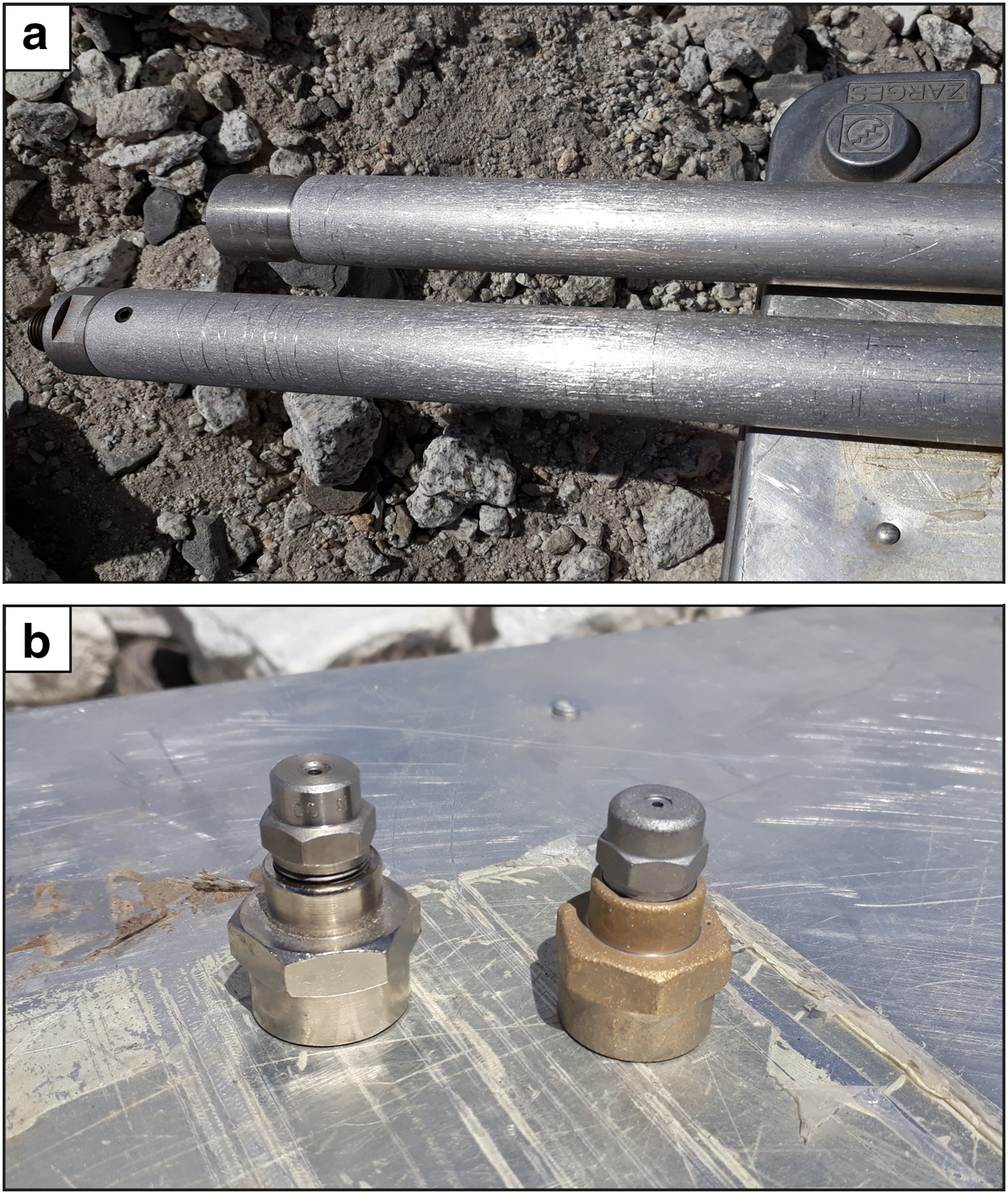
Fig. 4. Images of drill equipment wear from contact with englacial debris. (a) Drill stems showing abrasion; (b) drill nozzles (unused on the left and used on the right). Note the chrome plating has worn completely from the used reducing bush on the right.
In 2017, drilling of the longest borehole (BH17-13; Table 1) took two full days, with 102.4 m drilled on the first day and 52.6 m on the second. The average drilling rate was 0.29 m min−1, with rates varying between 0.12 and 0.46 m min−1 for 5–10 m sections (Fig. 5). In 2018, drilling of the longest borehole (BH18-04) also took two days, with 103 m drilled on the first day and 89 m on the second. The average drilling rate was 0.52 m min−1, varying between 0.24 and 0.96 m min−1 for 10–20 m sections. For comparison, rates of 0.45–1.17 and 0.5–2.0 m min−1 were achieved using similar equipment at (low-elevation) Rhonegletscher, Switzerland (Tsutaki and Sugiyama, Reference Tsutaki and Sugiyama2009), and Haut Glacier d'Arolla, Switzerland (Hubbard and Glasser, Reference Hubbard and Glasser2005), respectively.
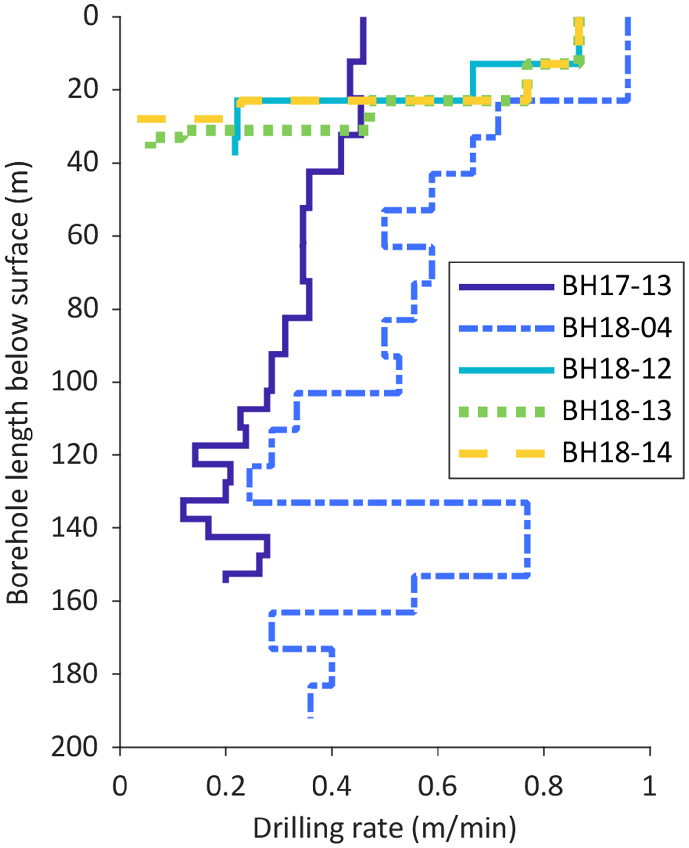
Fig. 5. Drilling rates by length for boreholes at Sites 3 (BH17-13), 4 (BH18-04) and 5 (BH18-12, BH18-13 and BH18-14) which were over 20 m in length and where drilling rates were recorded.
3.2.2. Borehole verticality
Great difficulty was encountered in drilling boreholes that were vertical at Khumbu Glacier. The slow drilling rates, combined with the need to drill manually rather than over the tripod and sheave wheel (Section 2.3.3) and the accumulated debris within each borehole (Section 3.2.1), often combined to result in substantial deviation from vertical.
Borehole inclinometry is only available for the four boreholes that were logged with an optical televiewer (OPTV) immediately after drilling (Table 1; Fig. 6). In 2017, BH17-13 reached a maximum inclination of ~30° from vertical at the borehole base (Fig. 6). As a result, while the borehole length was 155 m, the base of the borehole (‘borehole depth’) was only 132 m below the ice surface. In 2018, the deviation was less significant, likely because of the improved pump and burner performance (Section 3.1.3). For BH18-04, the maximum inclination was ~11° from vertical at 100 m below the surface, but by 150 m this had returned to 3.6° (Fig. 6).
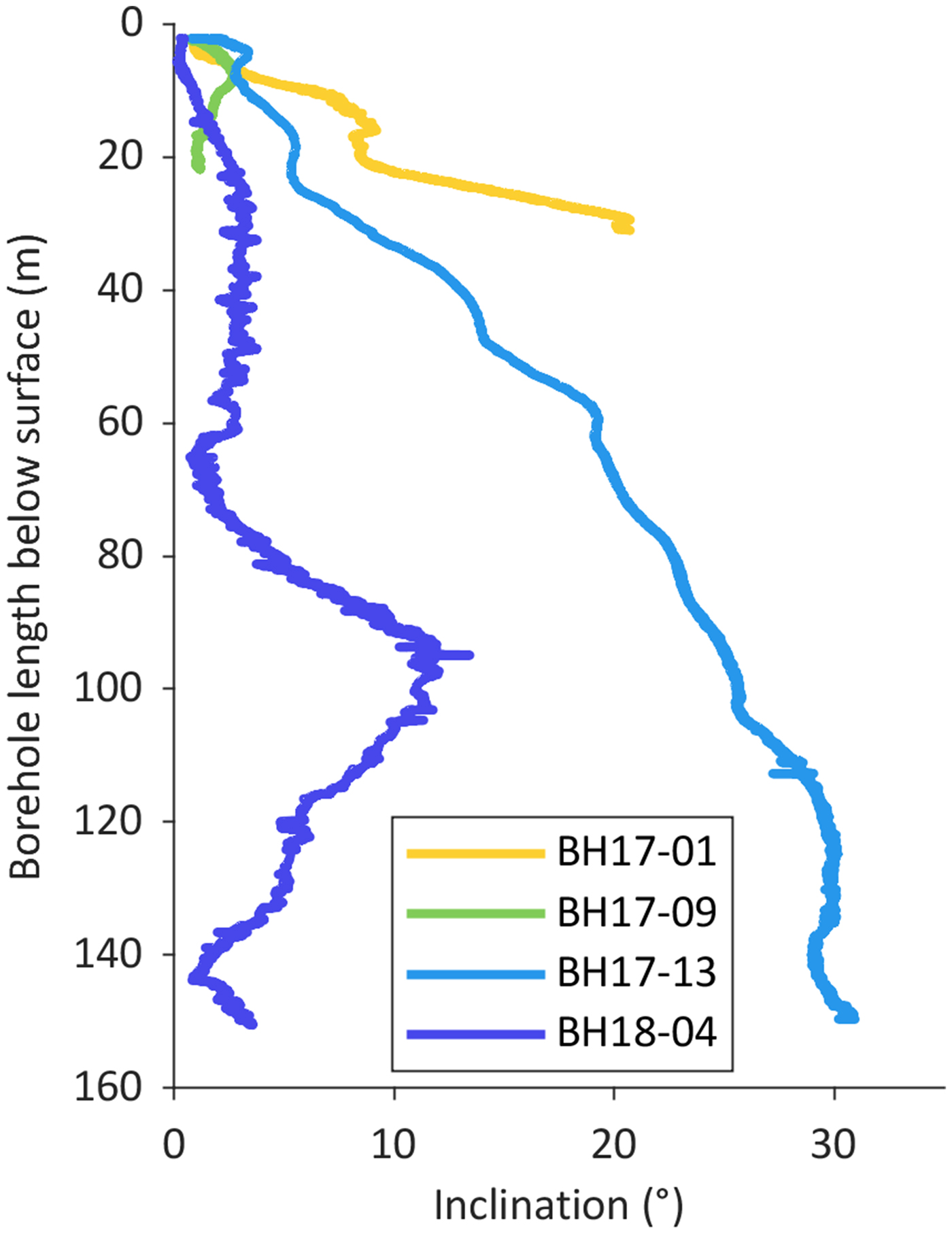
Fig. 6. Inclination from vertical of boreholes that were logged by an optical televiewer (OPTV). The maximum length of these logs (150 m) was limited by the OPTV cable length.
3.2.3. Borehole completion
For all boreholes other than BH18-04, which was limited by hose length, drilling ceased due to either impassable debris or the drilling rate slowing such that continued effort was futile. Images of several typical boreholes, drilled at Site 5 in 2018, are shown in Figure 7, illustrating the difficulties encountered during drilling. BH18-08 and BH18-09 (Fig. 7a) were abandoned at 1 m after they connected to a shallow englacial fracture, drained into the adjacent pond (left of image) and no further progress was made. Two test boreholes, separated laterally by < 2 m, were blocked terminally at < 1 m depth: one by coarse sediment (Fig. 7b) and the other by a substantial layer of fine sediment (Fig. 7c). BH18-12 (Fig. 7d) continued through relatively debris-free ice to 38 m, at which point further progress was prevented, probably by a thick layer of englacial debris. This was likely also the case for all boreholes at Site 2, where the maximum borehole length was 22.6 m (Fig. 3d).
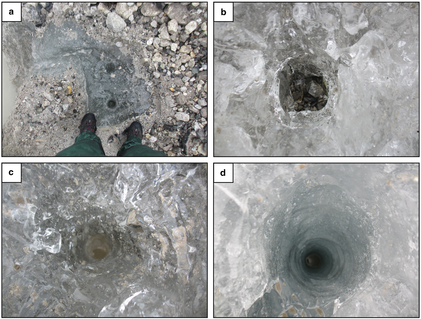
Fig. 7. Images of boreholes drilled on Khumbu Glacier at Site 5 in 2018. (a) BH18-08 and BH18-09 (abandoned at 1 m), showing cleared debris around boreholes; (b) test borehole 1, abandoned at < 0.5 m due to debris; (c) test borehole 2, abandoned at < 1 m due to sediment and debris inclusions; (d) BH18-12 (abandoned at 38 m), which partly drained at ~7 m below the surface (water-level lowered by ~1.5 m). All boreholes were a similar diameter (~0.1 m).
The only borehole that may have reached the bed of Khumbu Glacier was BH17-02 (Fig. 3e). However, the lack of any hydraulic indication of a subglacial drainage system, such as a change in borehole water-level, undermines certainty. Nevertheless, several boreholes partially drained, indicating a hydrological connection (Pohjola, Reference Pohjola1994; Copland and others, Reference Copland, Harbor, Gordon and Sharp1997; Gordon and others, Reference Gordon2001; Fountain and others, Reference Fountain, Jacobel, Schlichting and Jansson2005) to either the supraglacial hydrological system, such as at boreholes BH18-08 to BH18-11 (described above), or to a shallow englacial network. The latter was suggested at both BH18-12, by its drainage at ~7 m below the surface (Fig. 7d), and BH18-14, in which the borehole water-level lowered post-drilling. Alternatively, if a borehole encounters a pressurised, active conduit, the borehole will overflow (Hubbard and Glasser, Reference Hubbard and Glasser2005), as occurred at BH18-13 at Site 5, which overflowed for at least several days after drilling.
3.3. Changes in surface topography
After drilling, one borehole at each site (Figs 3c to h) was instrumented with strings of thermistor sensors to measure time-series of ice temperature (Miles and others, Reference Miles2018) and shear strain (tilt) at multiple depths. A basal multiprobe to measure hydrological electrical conductivity, pressure, temperature and turbidity was also installed at a single depth – usually the borehole base – at selected sites (Table 1). Sensors were wired to a data logger at the surface and left to record continually between field seasons. However, changes in the surface topography of debris-covered glaciers can be extremely rapid (Immerzeel and others, Reference Immerzeel2014), which created a challenge in determining safe locations for data loggers to be left. The need for boreholes to be in close proximity to a supraglacial pond (Section 2.3.1) meant the likelihood of surface change was even greater due to the potential for expanding supraglacial ponds and ice cliffs during the monsoon melt season, and subsequent loose debris (Benn and others, Reference Benn, Wiseman and Hands2001; Watson and others, Reference Watson2017).
At Site 1, where boreholes were drilled between two large supraglacial ponds (Fig. 3e), data loggers were removed within 3 weeks of installation due to pre-monsoon surface changes (Figs 8a, b). During this short interval, the water-level of the adjacent ponds rose 0.8 m and pond-marginal ice cliffs were observed to be backwasting rapidly (Fig. 8b), threatening the position of the data logger. These concerns were later validated during a return trip in October 2017, when both boreholes had been engulfed by the ponds. While the drill site had re-emerged by May 2018 due to a net water-level decrease over the year (Fig. 8c), the sensor strings were determined to have snapped before October 2017, likely due to debris slumping as the pond expanded.
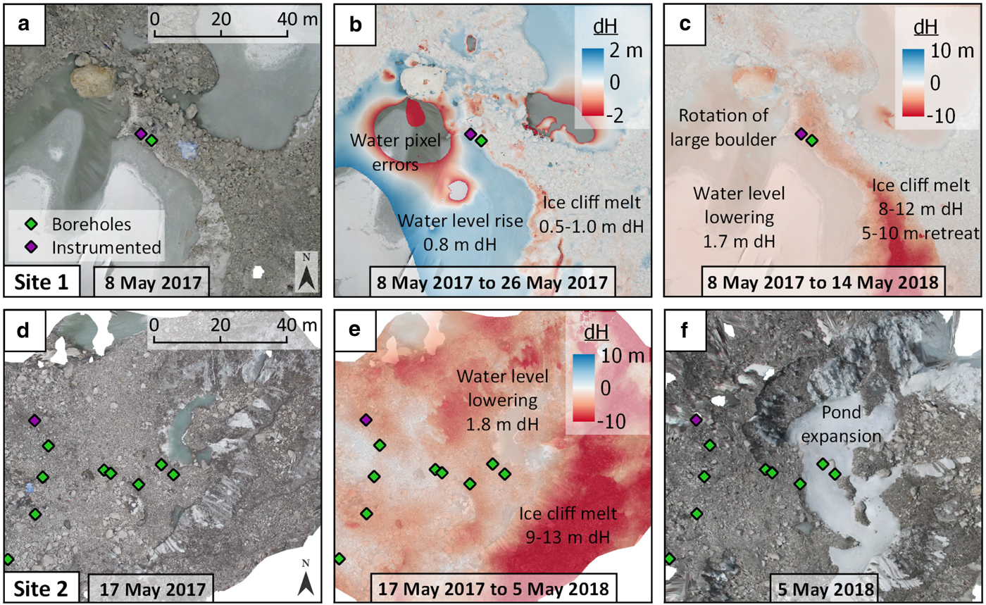
Fig. 8. Surface topographical change at Sites 1 and 2 between 2017 and 2018. (a) Site 1 orthoimage based on a terrestrial Structure-from-Motion survey on 8 May 2017. Surface elevation changes are shown for Site 1 on 26 May 2017 (b) and 14 May 2018 (c), relative to 8 May 2017, based on co-registered terrain models derived from repeats of the survey. (d) Site 2 orthoimage based on a terrestrial Structure-from-Motion survey on 17 May 2017. Surface elevation changes are shown for Site 2 on 5 May 2018 (e) relative to 17 May 2017, based on co-registered terrain models derived from a repeat survey. (f) The resulting orthoimage from 5 May 2018.
At Site 2, considerable surface lowering between May and October 2017 resulted in the sensor strings on the surface also being severed by slumping debris (Figs 8d–f). The data logger had travelled several metres downslope when retrieved in October 2017, despite having been located on a large and seemingly stable rock in May 2017. While Site 3 also experienced much surface topographical change between May 2017 and 2018, including melting glacier pedestals in the surrounding area, the data logger has remained stable for 2 years since May 2017.
Two boreholes were instrumented at Site 5 in May 2018, with data loggers secured above an emerging pond. Here, pond expansion was much more rapid than anticipated; in November 2018 the logger was retrieved from within this pond. No other sites visited in November 2018 had experienced such a topographical change, and all data loggers have remained intact and stationary since May 2018.
4. Methodological adaptations for future hot-water drilling
4.1. Use up to 5200 m a.s.l.
While our hot-water drilling equipment and methods were predominantly successful at Khumbu Glacier up to 5200 m a.s.l., we did encounter difficulties (Section 3). We outline some possible solutions below that would allow more effective and rapid future hot-water drilling at such elevations.
As noted above, a more slowly rotating spool would allow the use of the spool motor, tripod and sheave wheel, thereby increasing drilling rate consistency and borehole verticality. Heavier drill stems may also aid in this respect – although the ~20 kg stem was considered adequate matched to the EverDrill hose.
A potential solution to drill deeper boreholes at a faster rate would be to run several pumps and/or diesel burners to increase water and heat supply, respectively. For example, temperatures of 70–80°C have been reached on Store Glacier, Greenland, by running three Kärcher HDS 1000 De units in parallel (Doyle and others, Reference Doyle2018), and 80–90°C achieved with six to eight heating units on Jakobshavn Isbræ, Greenland, producing mean drilling rates of 1.29 m min−1 (Iken and others, Reference Iken, Echelmeyer, Harrison and Funk1993). However, the use of multiple units would involve greater logistical demands and reduce portability once on the glacier.
Finally, the Honda WX10 water pump was underspecified for the elevation of Khumbu Glacier. This could be overcome by using an alternative pump with a larger combustion engine (e.g. Honda WB20 or WH20) or using an electric water pump powered by a separate generator.
4.2. Use above 5200 m a.s.l.
More fundamental adaptions would be required to deploy EverDrill-style drilling equipment at even higher elevations. The principal challenge would be the supply of oxygen to the high-pressure pump carburettor. We have already found the HDS 801 B used in 2017 to be underpowered for our purpose; while the HD 9/23 G used in 2018 was better, it was also clear that the engine was operating at its elevational limit (Section 3.1.3). This was improved in the field by removing the filter from the GX390's air intake, and may have been enhanced further by disabling the engine's automatic throttle and operating it manually. Ultimately, however, the motor needs more oxygen, most likely supplied by a forced induction system such as a turbocharger or supercharger. These solutions are possible, and a supercharger could be driven by a separate motor, but both would require bespoke engineering and – to our knowledge – neither has yet been developed for general availability.
Although carburettor rejetting was largely successful for our EverDrill boreholes at elevations of up to ~5200 m a.s.l., Honda's off-the-shelf fuel nozzles are limited to three ranges, considered appropriate to a maximum of 4500 m a.s.l. (Fig. 1). Above this, even their smallest fuel nozzle is larger than that required for maximum efficiency, a limitation that will eventually prevent combustion altogether. Thus, nonstandard rejetting may be necessary for combustion motor use above ~5200 m. An alternative solution might be to partly or entirely replace the combustion-driven power with solar power. While the high-energy demand of producing hot, pressurised water largely precludes solar power, high-elevation boreholes can be cored by solar-powered electro-mechanical systems (e.g. Thompson, Reference Thompson2017). However, unless a core is needed for direct analysis, mechanical coring cannot match the flexibility, rapidity or portability of hot-water drilling.
Finally, hot-water drilling at higher elevations may suffer from the absence of a ready supply of liquid water. In such cases, sufficient snow can be melted to begin drilling and thereafter that water, supplemented by newly-melted ice, can be recirculated from the borehole. Such a method would require additional equipment, and thus also more processes to monitor during drilling. Recirculation may not be necessary if only short boreholes are planned.
5. Conclusions
We have presented our experiences of, and adaptations to, a hot-water drilling methodology on the high-elevation debris-covered Khumbu Glacier, Nepal. This drilling programme allowed us to acquire novel 3D measurements of the thermal structure (Miles and others, Reference Miles2018), dynamics and composition of a high-elevation Himalayan debris-covered glacier, which are still being analysed. Over two field seasons of 6–8 weeks each, we drilled a total of 27 boreholes with a cumulative length of 760.9 m. Our modular set-up of 2018 was more effective and robust than the less-powerful combined pressure-heater unit of 2017, resulting in boreholes being drilled more rapidly and closer to vertical. While some challenges can be – and were – overcome by equipment adaptations, others (such as encountering englacial debris and surface change during the monsoon season) are inherent to working on high-elevation (Asian or Andean) debris-covered glaciers, and their adverse influence can only be considered and possibly minimised by site selection.
The ability to measure properties and processes at high-elevation (and debris-covered) glaciers could contribute substantially to the parameterisation of numerical models aimed at robust forecasts of glacier evolution. These properties include thermal structure and dynamics, as well as ice thickness and hydrological measurements and experiments, for which virtually no observations exist across High Mountain Asia. Future deployments, with the methodological improvements proposed in Section 4.1, could allow more widespread observations of the glacier subsurface, particularly in the upper ablation area approaching the Khumbu Icefall. It may also allow the bed to be reached, enabling ice thickness to be measured and any subglacial drainage to be identified and investigated. Other appealing targets for future work include similar studies at other high-elevation debris-covered glaciers across High Mountain Asia, as the broader representivity of Khumbu Glacier is unknown, as well as examining dynamics of surging glaciers across the region. With the further adaptations to the drill equipment suggested in Section 4.2, the method could be deployed to reconstruct and characterise high-elevation thermal regimes and accumulation rates for the first time. Better understanding of all high-elevation glaciers, debris-covered or otherwise, will help to improve predictions of how these glaciers will respond to future climatic changes, and thus their projected contributions to water resources for vast populations.
Supplementary material
The supplementary material for this article can be found at https://doi.org/10.1017/jog.2019.49
Acknowledgements
This research was supported by the ‘EverDrill’ Natural Environment Research Council Grant awarded to Aberystwyth University (NE/P002021) and the Universities of Leeds and Sheffield (NE/P00265X). Support for equipment also came from HEFCW Capital Equipment Grant awarded to Aberystwyth University. KM is funded by an AberDoc PhD Scholarship (Aberystwyth University). Kärcher U.K. provided invaluable technical support in the development of an elevation-adapted drilling unit, and donated the equipment used in 2018. We thank Himalayan Research Expeditions and Rijan Kayastha for organising logistics and fieldwork permits, and Mahesh Magar for invaluable assistance in the field. We thank Samuel Doyle and Tom Chase for assisting with equipment preparation. Emily Potter, Tenzing Chogyal Sherpa and Dawa Tshering Sherpa also provided support during drilling. We acknowledge the support of the Sagarmatha National Park and their assistance with permitting.
Author contributions
DQ conceived of and led the EverDrill project, which was co-led by BH and AR. MP collaborated with EM and BH to ruggedise and adapt the Kärcher units for field use at high elevations. KM, EM, BH, DQ and AR participated in fieldwork. KM and EM led manuscript writing, to which all authors contributed.


 Open access