


1. Introduction
Submerged canopies are present in many aquatic ecosystems, including coral reefs, seagrass meadows as well as salt marshes and dwarf mangroves (during high tide and storm surge). These ecosystems serve multiple ecological and environmental functions. For example, these canopies provide shelter, nursery habitat and food sources for fish (Costanza et al. Reference Costanza, d'Arge, de Groot, Farberl, Grassot, Hannon, Limburg, Naeem and O'Neilltt1997; Waycott, Longstaff & Mellors Reference Waycott, Longstaff and Mellors2005; Whitfield Reference Whitfield2017). They improve water quality by filtering nutrients (De Los Santos et al. Reference De Los Santos2020) and capturing suspended sediments (Palmer et al. Reference Palmer, Nepf, Pettersson and Ackerman2004). The canopy resistance reduces current and waves, which reduces bed erosion and enhances coastal stability (Gedan et al. Reference Gedan, Kirwan, Wolanski, Barbier and Silliman2011).
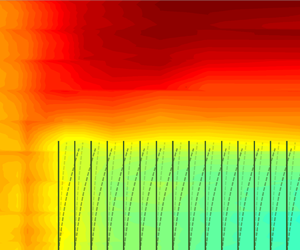
The resistance of the canopy can significantly alter the flow structure and hydrodynamic properties within and above a submerged canopy (Villanueva et al. Reference Villanueva, Paul, Vogt and Schlurmann2017). As illustrated in figure 1, when flow enters a submerged canopy with canopy height  ${h_p}$, two distinct flow regions are formed, the in-canopy and above-canopy layer. Note that, for a flexible canopy, the effective canopy height is smaller than the fully erect plant height when plants move in response to hydrodynamic forces. Within the canopy layer, the horizontal velocity gradually decelerates from the leading edge due to canopy drag. This results in a deflection of flow into the above canopy layer, which causes an increase in the above-canopy velocity. Velocities within and above the canopy are referenced by subscripts 1 and 2, respectively. After an adjustment length X, the time-mean current reaches a new equilibrium, called the fully developed flow structure. The adjustment length X is inversely proportional to the canopy drag, ${C_D}a$, with ${C_D}$ the drag coefficient and a the canopy density defined as the frontal area per canopy volume. Based on equation (10) in Chen, Jiang & Nepf (Reference Chen, Jiang and Nepf2013) and equation (5.1) in Lei & Nepf (Reference Lei and Nepf2021), $X/{h_p} \approx 1$ to 20 for canopy density (defined as the plant frontal area per bed area) $a{h_p} = 0.1$ to 10, which is a typical range for submerged canopies, and the shallow submergence $2 < h/{h_p} < 5$, where h is the water depth.

Figure 1. Illustration of velocity modification due to canopy resistance. Here,  ${U_c}$ is the imposed current and ${U_w}$ is the wave orbital velocity defined upstream of the canopy. Subscripts 1 and 2 denote velocity in the canopy layer and in the free-stream layer above the canopy, respectively, h and ${h_p}$ are the water depth and canopy height, respectively, X is the velocity adjustment length and $\delta $ is the penetration length describing the length scale of turbulent momentum exchange between the two layers.
The canopy velocity structure determines the transport of sediment, pollutants, pollen, plant seeds and fish larvae through submerged ecosystems (Falter, Atkinson & Merrifield Reference Falter, Atkinson and Merrifield2004; Lowe, Koseff & Monismith Reference Lowe, Koseff and Monismith2005b; Reidenbach et al. Reference Reidenbach, Koseff, Monismith, Steinbuckc and Genin2006; Malul, Holzman & Shavit Reference Malul, Holzman and Shavit2020; Huai et al. Reference Huai, Li, Katul, Liu and Yang2021; Stride et al. Reference Stride, Abolfathi, Odara, Bending and Pearson2023). Further, for some hydrodynamic conditions, the physical mass transfer was found to control the nutrient uptake rate by submerged ecosystems (Falter et al. Reference Falter, Atkinson and Merrifield2004; Larned, Nikora & Biggs Reference Larned, Nikora and Biggs2004; Morris et al. Reference Morris, Peralta, Brun, Van Duren, Bouma and Perez-Llorens2008). For example, the ammonium uptake in Cymodocea nodosa meadow was twice that observed for a Zostera noltii meadow, which was attributed to a doubling of the in-canopy velocity (Morris et al. Reference Morris, Peralta, Brun, Van Duren, Bouma and Perez-Llorens2008). Hydrodynamic models that can accurately predict the in-canopy and above canopy velocity provide a useful tool to understand and quantify the mass transfer and nutrient uptake in submerged ecosystems (Lowe et al. Reference Lowe, Koseff and Monismith2005b; Stride et al. Reference Stride, Abolfathi, Odara, Bending and Pearson2023).
Previous studies have described the velocity field associated with submerged canopies for a uni-directional current in both the fully developed (Luhar & Nepf Reference Luhar and Nepf2013) and the adjustment regions (Chen et al. Reference Chen, Jiang and Nepf2013; Lei & Nepf Reference Lei and Nepf2021). For a deeply submerged canopy, defined as a water depth to canopy height ratio  $h/{h_p} > 10$, the flow within the canopy is driven by the turbulent stress at the top of the canopy (Nepf Reference Nepf2012). For shallow submergence ( $1 < h/{h_p} < 5$), canopy flow is driven by both the turbulent stress and potential gradients (Nepf Reference Nepf2012). Many canopies exist within the submergence range $1 < h/{h_p} < 5$. For example, seagrasses usually colonize water depths $1 < h < 10\ \textrm{m}$ (Duarte Reference Duarte1991), with canopy height ${h_p} = 0.1$ to 1 m (based on the blade length summarized in table 3 in Luhar et al. Reference Luhar, Coutu, Infantes, Fox and Nepf2010 and table 1 in Hansen & Reidenbach Reference Hansen and Reidenbach2012), corresponding to $1 < h/{h_p} < 100$. For many intertidal salt marshes, ${h_p} = 0.4$ to 0.9 m, with water depths in the range from $h = 0.8$ to 2 m, varying from an emergent to submerged state over a tide cycle with $1 < h/{h_p} < 5$ when submerged (e.g. Ysebaert et al. Reference Ysebaert, Yang, Zhang, He, Bouma and Herman2011; Garzon et al. Reference Garzon, Maza, Ferreira, Lara and Losada2019; Zhang et al. Reference Zhang, Lin, Gong, Li and Chen2020).
The canopy resistance is often described by the dimensionless canopy density,  $a{h_p}$ (the plant frontal area per bed area). For many coastal canopies, e.g. salt marshes, seagrasses and mangroves summarized in Nepf (Reference Nepf2012), $a{h_p} > 0.1$, indicating that the canopy drag is large compared with the bed drag and generates a shear layer with an inflection point near the top of the canopy. The in-canopy time-mean velocity ${U_{c1}}$ is decreased and the above-canopy time-mean velocity ${U_{c2}}$ is increased compared with the depth-averaged ${U_c}$ (Chen et al. Reference Chen, Jiang and Nepf2013; Lei & Nepf Reference Lei and Nepf2021). Specifically, the ratio of ${U_{c1}}$ to ${U_c}$, defined as time-mean velocity reduction ${\alpha _c}$, is significantly smaller than 1, i.e. ${\alpha _c} = {U_{c1}}/{U_c} \ll 1$ (figure 1). Theoretical models have been developed to predict the in-canopy and above canopy current velocity (Chen et al. Reference Chen, Jiang and Nepf2013; Lei & Nepf Reference Lei and Nepf2021). For example, Chen et al. (Reference Chen, Jiang and Nepf2013) predicted the current velocity within an array of rigid cylinders based on the continuity and momentum equations within and above the canopy (1.1), herein noted as the CJN model after the authors' names
 \begin{equation}{\alpha _c} = \frac{{{U_{c1}}}}{{{U_c}}} = \frac{1}{{1 - \dfrac{{{h_p}}}{h}{\lambda _p} + \sqrt {\dfrac{{{C_D}a{h_p}}}{{2C(1 - {\lambda _p})}}{{\left( {\dfrac{{h - {h_p}}}{h}} \right)}^3}} }},\end{equation}
in which  ${\lambda _p} = {V_p}/{h_p}$ is the solid volume fraction within the canopy, ${V_p}$ is the submerged plant volume per bed area and C characterizes the turbulent momentum exchange between the canopy and over-flow layers. Previous studies have suggested (Konings, Katul & Thompson Reference Konings, Katul and Thompson2012)
 \begin{equation}C = {K_c}{\left( {\frac{\delta }{h}} \right)^{1/3}},\end{equation}
in which  ${K_c} = 0.07 \pm 0.02$ (SD, standard deviation) is an empirical constant (Chen et al. Reference Chen, Jiang and Nepf2013), $\delta $ is the penetration length that quantifies the vertical extent of the shear layer within the canopy. Chen et al. (Reference Chen, Jiang and Nepf2013) assumed $\delta = 0.23/({C_D}a)$ for $h/{h_p} \ge 2$ and $\delta = 0.23(h/{h_p} - 1)/({C_D}a)$ for $h/{h_p} < 2$. Recently, Lei & Nepf (Reference Lei and Nepf2021) extended the CJN model to flexible canopies and to describe the evolution of velocity from the leading edge for both wide (two-dimensional) submerged canopies and submerged canopies of finite width (three-dimensional), referred to as the L&N model. The L&N model improved the parameterization of turbulent momentum exchange between the two layers by considering the physical limits of the penetration length $\delta $, which is constrained by the canopy height ( ${h_p}$) and the depth of water above the canopy ( $h - {h_p}$)
 \begin{equation}\delta = \min \left( {\frac{{0.3 \pm 0.1}}{{{C_D}a}},h - {h_p},{h_p}} \right)\!.\end{equation}
Considering the relative magnitudes of the inertial and drag forces in a range of natural canopies, the reduction of the wave orbital velocity within the canopy is significantly less than the reduction of a uni-directional current (Lowe, Koseff & Monismith Reference Lowe, Koseff and Monismith2005a). As a result, waves are often more important than current for generating in-canopy fluid motion that enhances the nutrient uptake and mass transfer, e.g. within coral reefs (Hearn, Atkinson & Falter Reference Hearn, Atkinson and Falter2001; Falter et al. Reference Falter, Atkinson and Merrifield2004, Falter, Atkinson & Coimbra Reference Falter, Atkinson and Coimbra2005; Reidenbach et al. Reference Reidenbach, Koseff, Monismith, Steinbuckc and Genin2006) and seagrasses (Thomas & Cornelisen Reference Thomas and Cornelisen2003). The reduction of the in-canopy wave orbital velocity has been described by a two-layer model (Lowe et al. Reference Lowe, Koseff and Monismith2005a), called the LKM model
 \begin{equation}\frac{{\partial ({U_{w1}} - {U_{w2}})}}{{\partial t}} = \frac{{|{{U_{w2}}} |{U_{w2}}}}{{{L_S}}} - \frac{{|{{U_{w1}}} |{U_{w1}}}}{{{L_D}}} - \frac{{{C_M}{\lambda _p}}}{{1 - {\lambda _p}}}\frac{{\partial {U_{w1}}}}{{\partial t}},\end{equation}
in which  ${L_S} = 2{h_p}/{C_f}$ is the shear length scale, ${L_D} = 2{h_p}(1 - {\lambda _P})/({C_D}a{h_p})$ is the drag length scale, ${C_f}$ is the friction coefficient for the canopy interface and ${C_M}$ is the inertial force coefficient. Although Lowe et al. (Reference Lowe, Koseff and Monismith2005a) considered waves with a background current in their experiments, (1.4) was derived for the wave component only. The reduction in the wave orbital velocity within the canopy is described by $\alpha _w^\ast= {U_{w1}}/{U_{w2}}$, i.e. the ratio of the wave orbital velocity for the two layers at the same x position. When inertial forces dominate, (1.4) reduces to
 \begin{equation}\alpha _w^\ast= \frac{{{U_{w1}}}}{{{U_{w2}}}} = \frac{{(1 - {\lambda _p})}}{{1 + ({C_M} - 1){\lambda _p}}}.\end{equation}
When the wave period is infinitely long, (1.4) approaches the unidirectional limit, for which a simplified solution for the time-mean velocity reduction is (Lowe et al. Reference Lowe, Koseff and Monismith2005a)
 \begin{equation}\alpha _c^\ast= \frac{{{U_{c1}}}}{{{U_{c2}}}} = \sqrt {\frac{{{L_D}}}{{{L_S}}}} .\end{equation}
 Note that the LKM model defined the canopy velocity reduction relative to the velocity above the canopy, and a superscript * was added to distinguish this from the definition used in the CJN and L&N models, in which the canopy velocity reduction is defined relative to the imposed velocity unaffected by the canopy ( $U$), i.e. ${\alpha _c} = {U_{c1}}/{U_c}$. With these definitions, $\alpha _c^\ast < {\alpha _c}$, because flow diverted from the canopy to the overflow layer results in ${U_{c2}} > {U_c} > {U_{c1}}$. To make comparisons between different models and with measurements from different studies, the reduction coefficients can be transformed considering the mass conservation through the canopy (equation 18 in Chen et al. Reference Chen, Jiang and Nepf2013, see also (2.10) in the present study)
 \begin{equation}\alpha _c^\ast= \frac{{{\alpha _c}(h - {h_p})}}{{h - {\alpha _c}{h_p}(1 - {\lambda _p})}}.\end{equation}
 For many natural canopies, the reduction in wave orbital velocity is in the range of  $\alpha _w^\ast= 0.68$ to 0.99. The lowest values of $\alpha _w^\ast $ are associated with very dense canopies, e.g. rigid canopies with D = 50 mm and a density of 100 stems m−2 (Lowe et al. Reference Lowe, Koseff and Monismith2005a) or D = 6.4 mm and a density of 3100 stems m−2 (van Rooijen et al. Reference van Rooijen, Lowe, Rijnsdorp, Ghisalberti, Jacobsen and McCall2020). In comparison, the current ratio falls in the range of $\alpha _c^\ast= 0.03$ to 0.3, which is much smaller than the wave ratio, indicating that the time-mean current experiences a much greater reduction within a canopy compared with the wave velocity (Luhar et al. Reference Luhar, Coutu, Infantes, Fox and Nepf2010). Further, submerged canopies are often exposed to combined current and waves. In these combined conditions, current and waves may affect one another, so that the in-canopy time-mean current and wave orbital velocity should be predicted together. As introduced above, the LKM model predicts current and wave orbital velocity reduction as two limits of behaviour with respect to wave excursion, and it cannot describe the interaction between currents and waves. The first effort to predict current and wave velocity together was made in Zeller et al. (Reference Zeller, Zarama, Weitzman and Koseff2015). Specifically, they developed a one-dimensional Reynolds-averaged Navier–Stokes model, herein called the ZWK model
 \begin{equation}\frac{{\partial {U_1}}}{{\partial t}} + \frac{{{{[UW]}_{{h_p}}}}}{{{h_p}}} =- \frac{1}{\rho }\frac{{\partial P}}{{\partial x}} + \frac{{{{ {{\tau_{xz}}} |}_{{h_p}}}}}{{{h_p}}} - \frac{1}{2}\frac{{{C_D}a|{{U_1}} |{U_1}}}{{1 - {\lambda _p}}} - \frac{{{C_M}{\lambda _p}}}{{1 - {\lambda _p}}}\frac{{\partial {U_1}}}{{\partial t}},\end{equation}
in which  ${U_1}$ and ${U_2}$ are the total velocity in the canopy and free-stream layer, respectively, W is the vertical velocity and P is pressure. The shear stress at the top of the canopy is modelled as ${ {{\tau_{xz}}} |_{{h_p}}} = C_{Sm}^2|{{U_2} - {U_1}} |({U_2} - {U_1})$, with ${C_{Sm}}$ the Smagorinsky coefficient (Vreman, Geurts & Kuerten Reference Vreman, Geurts and Kuerten1997). Assuming W follows linear wave theory, the vertical advection at the interface of the two flow layers is modelled as
 \begin{equation}\frac{{{{[UW]}_{{h_p}}}}}{{{h_p}}} =- \frac{{(h - {h_p}){U_1} + {h_p}{U_2}}}{h}\frac{1}{{\rho \sqrt {gh} }}\frac{{\partial P}}{{\partial x}}.\end{equation}
 Equation (1.8) predicts the total time-varying in-canopy velocity  ${U_1}$, which is the sum of time-mean ${U_{c1}}$ and wave orbital ${U_{w1}}$, such that both $\alpha _c^\ast $ and $\alpha _w^\ast $ can be obtained. In the current limit, (1.8) reduces to
 \begin{equation}\alpha _c^\ast= \frac{{\sqrt {\dfrac{{{L_D}}}{{{L^{\prime}_S}}}} }}{{\sqrt {\dfrac{{{L_D}}}{{{L^{\prime}_S}}}} + \sqrt {1 - \dfrac{{{h_p}}}{h}} }},\end{equation}
in which the shear length scale is defined by  ${L^{\prime}_S} \equiv {h_p}/C_{Sm}^2$. The difference between (1.10) and (1.6) comes from the fact that (1.10) considers the pressure gradient for unidirectional flow, which is neglected in the ZWK model (1.6).
Scale analysis shows that the ZWK model is only effective for a limited range of flow and canopy conditions. Specifically, the ZWK model (1.8) is applicable for  ${A_w}/{L_D} \ll 10$, ${L_D}/{L^{\prime}_S} \ll 1$, ${U_c}/{U_w}\sim O(1)$, $2 < h/{h_p} < 5$ and $Fr \ll 1$ (Zeller et al. Reference Zeller, Zarama, Weitzman and Koseff2015). Here, ${A_w}$ is the wave orbital excursion and $Fr = \sqrt {(U_c^2 + U_w^2)/(gh)}$ is the Froude number. However, natural canopy and flow conditions can have a much wider range of parameters. First, ${U_c}/{U_w}$ can vary between the current limit and wave limit, so that ${U_c}/{U_w}$ can range from 0 to infinity. Further, some natural canopies, such as salt marshes, vary from emergent (during low tide) to submerged (during high tide or storm surge), such that a shallow submergence, $1 < h/{h_p} < 2$, is a common natural condition (Ysebaert et al. Reference Ysebaert, Yang, Zhang, He, Bouma and Herman2011; Zhang et al. Reference Zhang, Lin, Gong, Li and Chen2020).
The present study developed a model for combined wave–current conditions to overcome the limitations of previous models. The new model is applicable to a much wider range of current and wave combinations, covers the limits of pure current and pure wave and can be applied to both rigid and flexible structures such as seagrasses and salt marshes. Experiments were conducted to measure detailed velocity profiles upstream of and within a submerged canopy formed of rigid cylinders under pure current, pure wave and combined current and wave conditions. The new model was validated using measurements in the present study as well as previous studies, including flexible seagrass and salt marsh plant models. The new model performed as well or better than previous models described in the literature (table 1).
Table 1. Models predicting in-canopy velocity for fully developed canopy flow.

2. Theoretical modelling
2.1. Force on individual plant
The impact of a canopy on the velocity field is described through the hydrodynamic drag generated by individual plants. Therefore, it makes sense to begin with a description of that drag. For greatest generality, we use a model that accounts for plant flexibility and morphology in both waves and current. Specifically, the drag force on a plant with multiple leaves (each is  ${l_l}$ long, b wide and d thick) distributed on a central stem (with diameter D and length ${l_s}$), ${F_d}$, has been described for both waves alone and in combination with current (Zhang & Nepf Reference Zhang and Nepf2021b, Reference Zhang and Nepf2022)
 \begin{equation}{F_d} = \underbrace{{{F_{r,l}}\{ {C_s}{N_l}{K_l}{{(C{a_l}{L_l})}^{ - 1/4}}\} }}_{{force\ on\ leaves}} + \underbrace{{{F_{r,s}}\{ {K_s}{{(C{a_s}{L_s})}^{ - 1/4}}\} }}_{{force\ on\ stem}}.\end{equation}
In (2.1), the time-varying drag forces on an individual rigid leaf ( ${F_{r,l}}$) and a rigid stem ( ${F_{r,s}}$) are modified by the bracketed terms that account for the reduction in drag due to leaf and stem reconfiguration. Throughout the manuscript, the subscripts l and s represent parameters associated with the leaves and stem, respectively, ${N_l}$ is the number of leaves on the plant, ${C_s}$ is the sheltering coefficient that reflects the drag reduction due to sheltering and interaction between leaves and stem and ${K_l}$ and ${K_s}$ are coefficients that reflect the geometric difference between a leaf (flat) and a stem (cylindrical). Specifically, based on measurements on an individual leaf, ${K_l} = 1$ (Lei & Nepf Reference Lei and Nepf2019b), and for a cylindrical stem ${K_s} = 1.2$ (Zhang, Lin & Nepf Reference Zhang, Lin and Nepf2021). The Cauchy number, $Ca$, is the ratio of hydrodynamic drag to the restoring force due to structural stiffness, see (2.4). Here, L is the length ratio between the structure length, l, and wave orbital excursion, ${A_w}$, see (2.5)
 \begin{gather}{F_{r,l}} = \frac{1}{2}\rho {C_{D,l}}b{l_l}|{{U_1}} |{U_1} + \rho {C_{M,l}}bd{l_l}\frac{{\partial {U_1}}}{{\partial t}},\end{gather}
 \begin{gather}{F_{r,s}} = \frac{1}{2}\rho {C_{D,s}}D{l_s}|{{U_1}} |{U_1} + \rho {C_{M,s}}\frac{{{\rm \pi} {D^2}}}{4}{l_s}\frac{{\partial {U_1}}}{{\partial t}}, \end{gather}
 \begin{gather}Ca = \frac{{\rho AU_{max}^2}}{{EI/{l^2}}},\end{gather}
 \begin{gather}L = \frac{l}{{{A_w}}},\end{gather}
 \begin{gather}{U_{max}} = \textrm{max(}|{{U_1}} |).\end{gather}
Here,  ${U_{max}}$ is the maximum in-canopy velocity. In (2.4), A is the frontal area, and $A = D{l_s}$ for a cylindrical stem and $A = b{l_l}$ for a flat leaf, E is the Young's modulus, I is the second momentum of area and $I = {\rm \pi}{D^4}/64$ for a cylindrical stem and $I = b{d^3}/12$ for a flat leaf.
Finally, flexible plants bend in response to flow, called reconfiguration, which reduces drag. The influence of plant flexibility on plant drag is captured by the scaling term  ${(Ca\,L)^{ - 1/4}}$ (2.1), which applies to waves with $L > 1$ and $Ca\,L > 1$. For $Ca\,L < 1$, the drag reduction is negligible and ${F_d} = {F_{r,l}}\{ {C_s}{N_l}{K_l}\} + {F_{r,s}}{K_s}$ (Luhar & Nepf Reference Luhar and Nepf2016; Henderson Reference Henderson2019; Lei & Nepf Reference Lei and Nepf2019b; Zhang & Nepf Reference Zhang and Nepf2021a). For pure current, the reconfiguration term ${(Ca\,L)^{ - 1/4}}$ in (2.1) is replaced by $C{a^{ - 1/3}}$ (Luhar & Nepf Reference Luhar and Nepf2011).
2.2. Fully developed in- and above-canopy velocity
The fully developed in- and above-canopy velocities are defined for x > X. Beyond this position, the time-mean velocity does not adjust further with increasing x, but the wave orbital velocity might decrease due to plant-induced wave energy dissipation. For simplicity, the evolution of the wave velocity with distance was not considered in the present model, which focused on the vertical adjustment of horizontal velocity in response to canopy drag. Consider a co-linear current  ${U_c}$ and wave ${U_w}$ that enter the canopy at $x = 0$. The total imposed velocity is defined as the depth-averaged velocity over $z = 0$ to h (figure 1)
 \begin{equation}U = {U_c} + {U_w}\,\textrm{cos(}\phi ),\end{equation}
in which  $\phi $ is the wave phase. After an adjustment length of X, the flow structure is fully developed, with a reduced in-canopy time-mean current ${U_{c1}}$ and wave orbital velocity ${U_{w1}}$, compared with the velocity in the absence of a canopy (without energy dissipation), which equals the imposed velocity ${U_c}$ and ${U_w}$. The above-canopy time-mean current ${U_{c2}}$ is increased. The degree of velocity reduction in the canopy is represented by $\alpha _c^\ast $ and $\alpha _w^\ast $ (figure 1). Assuming there is no phase difference in the vertical direction, the total in-canopy (defined as the depth average over $z = 0$ to ${h_p}$) and above-canopy (defined as the depth average over $z={h_p}$ to h) velocities are, respectively,
 \begin{gather}{U_1} = {U_{c1}} + {U_{w1}}\,\textrm{cos}(\phi ),\end{gather}
 \begin{gather}{U_2} = {U_{c2}} + {U_{w2}}\,\textrm{cos}(\phi ).\end{gather}
Conservation of mass requires that, at each phase of the wave, the sum of flux within each layer equals the depth-averaged flux, expressed as
 \begin{equation}U(\phi )h = {U_1}(\phi ){h_p}(1 - {\lambda _p}) + {U_2}(\phi )(h - {h_p}).\end{equation}
 Assume the bottom friction can be neglected relative to the canopy drag (i.e.  $a{h_p} > 0.1$), and the free-surface stress is zero, then the vertically averaged momentum equation in the canopy layer (2.11) and the overflow layer (2.12) are, respectively,
 \begin{gather}\frac{{\partial {U_1}(\phi )}}{{\partial t}} + \frac{{{W_1}(\phi ){U_1}(\phi )}}{{{h_p}}} + {U_1}(\phi )\frac{{\partial {U_1}(\phi )}}{{\partial x}} =- \frac{1}{\rho }\frac{{\partial {P_1}(\phi )}}{{\partial x}} + \frac{{{{ {{\tau_{xz}}} |}_{{h_p}}}}}{{{h_p}}} - \langle{F_d}(\phi )\rangle,\end{gather}
 \begin{gather}\frac{{\partial {U_2}(\phi )}}{{\partial t}} + \frac{{{W_2}(\phi ){U_2}(\phi )}}{{h - {h_p}}} + {U_2}(\phi )\frac{{\partial {U_2}(\phi )}}{{\partial x}} =- \frac{1}{\rho }\frac{{\partial {P_2}(\phi )}}{{\partial x}} - \frac{{{{ {{\tau_{xz}}} |}_{{h_p}}}}}{{h - {h_p}}}.\end{gather}
The bracket notation  $\langle \rangle$ defines the average drag over the canopy. Integrating the continuity equation over the canopy layer, ${W_1}(\phi ) =- {h_p}(\partial {U_1}(\phi )/\partial x)$. Substituting for ${W_1}$ in (2.11), the convective terms cancel. Similarly, in the overflow layer, ${W_2}(\phi ) =- (h - {h_p})(\partial {U_2}(\phi )/\partial x)$, and the convective terms cancel. The convective terms were also neglected in previous layer-averaged models (Lowe et al. Reference Lowe, Koseff and Monismith2005a; Weitzman et al. Reference Weitzman, Zeller, Thomas and Koseff2015; Jacobsen Reference Jacobsen2016). The pressure gradients are associated with the time-mean free-surface slope, which is hydrostatic, and the surface wave dynamic pressure. For shallow-water waves ( $kh \ll 1$), the dynamic pressure is $\rho g{a_w}\,\textrm{cos(}\phi )$ (Lin Reference Lin2008) and does not depend on the vertical position, such that $\partial {P_1}(\phi )/\partial x = \partial {P_2}(\phi )/\partial x$. Based on field measurements, e.g. data shown in Garzon et al. (Reference Garzon, Maza, Ferreira, Lara and Losada2019), Zhang et al. (Reference Zhang, Lin, Gong, Li and Chen2020) and Zhang, Lin & Chen (Reference Zhang, Lin and Chen2022a), offshore and coastal regions are often dominated by shallow to near shallow wave conditions with $kh = 0.1$ to 1. Considering shallow submergence, $h/{h_p} \ge 2$, the estimated pressure gradient for the canopy and free-stream layers differed by 20 % at maximum based on linear wave theory with finite water depth (Lin Reference Lin2008). Therefore, for simplicity, $\partial {P_1}(\phi )/\partial x = \partial {P_2}(\phi )/\partial x$ was considered in the model derivation and the model is theoretically valid for $kh \le 1$.
For  ${N_s}$ plants per bed area, the total canopy resistance per unit in-canopy fluid can be calculated from the force on an individual plant, ${F_d}(\phi )$. Specifically, $\langle {F_d}(\phi ) \rangle = (1/\rho )({F_d}(\phi ){N_s}/{h_p}(1 - {\lambda _p}))$. Using this and combining (2.11) and (2.12)
 \begin{equation}\frac{{\partial {U_2}}}{{\partial t}} - \frac{{\partial {U_1}}}{{\partial t}} = \frac{1}{\rho }\frac{{{F_d}{N_s}}}{{{h_p}(1 - {\lambda _p})}} - \frac{h}{{{h_p}(h - {h_p})}}{ {{\tau_{xz}}} |_{{h_p}}}.\end{equation}
 To simplify the notation, the phase  $\phi $ will be dropped, but keep in mind that each term varies with the wave phase. The plant drag ${F_d}$ is a function of in-canopy velocity ${U_1}$. The shear stress, ${ {{\tau_{xz}}} |_{{h_p}}}$, is a function of the velocity difference ${U_2} - {U_1}$. For combined current and wave conditions, we assume that the shear stress model developed for a unidirectional current is valid at each velocity phase, i.e.
 \begin{equation}{\tau _{xz}} = C|{{U_2} - {U_1}} |({U_2} - {U_1}),\end{equation}
in which C characterizes the turbulent momentum exchange between the two layers (1.2). Solving (2.10),  ${U_2} = RU + {R_1}{U_1}$ with $R = h/(h - {h_p})$, ${R_1} = {h_p}(1 - {\lambda _p})/(h - {h_p})$ and plugging ${U_2}$ into (2.13), we obtained ${U_1}$ as a function of $U$
$U$
 \begin{equation}{R_1}\frac{{\partial U}}{{\partial t}} - ({R_2} + 1)\frac{{\partial {U_1}}}{{\partial t}} = \frac{1}{\rho }\frac{{{F_d}{N_s}}}{{{h_p}(1 - {\lambda _p})}} - \frac{{{R_1}}}{{{h_p}}}C|{{R_1}U - ({R_2} + 1){U_1}} |({R_1}U - ({R_2} + 1){U_1}).\end{equation}
 Since  ${F_d}$ is a function of ${U_1}$ and plant properties (2.1), the only unknown variable, ${U_1}$, can be solved by (2.13) when ${U_2}$ is known, or by (2.15) when U is known. The predicted total velocity is then separated into a time-mean ${U_{c1}}$ and wave orbital velocity ${U_{w1}}$, which were used to quantify the velocity reduction parameters. For pure current, the time derivative is zero, and (2.15) reduces to (1.1), described by the CJN and L&N models (Chen et al. Reference Chen, Jiang and Nepf2013; Lei & Nepf Reference Lei and Nepf2021). With waves, (2.13) and (2.15) need to be solved numerically. The associated MATLAB code is described in the supplementary material available at https://doi.org/10.1017/jfm.2024.61.
2.3. Model coefficients
The inertia coefficient was set to  ${C_M} = 2$ for all conditions. The drag coefficient, ${C_D}$, was estimated from formulations described in the literature for pure current and pure wave conditions, as summarized in table 2. For pure waves, ${C_D}$ was determined by the Keulegan–Carpenter number ( $\textrm{KC}$) (Keulegan & Carpenter Reference Keulegan and Carpenter1958), with $\textrm{KC} = {U_{max}}{T_w}/D$ for cylinders and $\textrm{KC} = {U_{max}}{T_w}/b$ for a flat plate with b the plate width. The wave drag model was also applied for the combined current and wave conditions. Although Keulegan & Carpenter (Reference Keulegan and Carpenter1958) only considered pure wave conditions in their experiments, previous studies have shown that the ${C_D}$ dependence on KC also fits combined current and wave conditions, if KC is defined using the maximum horizontal velocity ${U_{max}} = \textrm{max(}|{{U_1}} |)$ ((2.6), for combined current and waves) instead of the wave orbital velocity ( ${U_{max}} = {U_\textrm{w}}$ for pure waves). Specifically, the drag coefficient shown in table 2 correctly predicted the drag force measured on individual plants under combined current and waves (Zhang & Nepf Reference Zhang and Nepf2022), and also predicted the measured wave dissipation by vegetation under the influence of current (Zhang & Nepf Reference Zhang and Nepf2021a). Drag coefficients were taken from figure A1 in Zhang, Lin & Nepf (Reference Zhang, Lin and Nepf2022b), but with an adjustment for submergence needed to account for the reduction in drag at the free end of a cylinder, i.e. at the top of a rigid canopy (e.g. see figure 7 and equation 18 in Ghisalberti & Nepf Reference Ghisalberti and Nepf2004). Specifically, for the array geometry considered, the canopy average drag coefficient was reduced by a factor of 0.64 compared with that of an infinite cylinder (Ghisalberti & Nepf Reference Ghisalberti and Nepf2004). The measured in-canopy velocity was used to predict ${C_D}$, such that, for each case, different models applied the same drag coefficient. When provided in the references, the reported drag coefficients were used for validation, as in Lowe et al. (Reference Lowe, Koseff and Monismith2005a) and Zeller et al. (Reference Zeller, Zarama, Weitzman and Koseff2015). A 20 % uncertainty in ${C_D}$ was assumed for all model predictions.
Table 2. Drag coefficient  ${C_D}$ and inertia coefficient ${C_M}$.

In addition to  ${C_D}$ and ${C_M}$, the LKM model requires a friction coefficient ${C_f}$ to describe the turbulent momentum exchange between layers. Poggi et al. (Reference Poggi, Porporato, Ridolfi, Albertson and Katul2004) fitted friction factors for submerged arrays in the range of ${C_f} = 0.005$ to 0.13. Similarly, Luhar & Nepf (Reference Luhar and Nepf2013) showed that ${C_f} = 0.04$ works well in predicting their canopy flow observations, and Lowe et al. (Reference Lowe, Koseff and Monismith2005a) found ${C_f} = 0.017$ to 0.032. Based on these studies, we assumed ${C_f} = 0.03 \pm 0.02$ in the LKM model to predict the velocity reduction and its uncertainty. Finally, the ZWK model requires a Smagorinsky coefficient ${C_{Sm}}$, which is suggested to fall between 0.1 and 0.2 (Vreman et al. Reference Vreman, Geurts and Kuerten1997). Consequently, ${C_{Sm}} = 0.15 \pm 0.05$ was applied in the ZWK model in this study. Finally, for flexible canopies, ${h_p}$ was assumed to be the mean deflected canopy height (see table S1 in the supplementary material).
3. Laboratory measurements of canopy flow velocity
To validate the proposed model, flume experiments were conducted in a 22 m long and 45 cm wide flume in the State Key Laboratory of Coastal and Offshore Engineering in Dalian University of Technology. For simplicity, the experiment used rigid cylinders with 6 mm diameter and 20 cm height distributed in a staggered array. The test canopy was 4 m long and filled the flume width. Three densities were considered, 284, 444 and 830 cylinders per bed area. The water depth was 40 cm, such that  $h/{h_p} = 2$. Eight pure current, seven pure wave and sixteen combined current and wave conditions were used. See all tested combinations of canopy and flow conditions in table S1 in the supplementary material.
The leading edge of the canopy was designated as  $x = 0$, with x positive in the streamwise direction. Velocity profiles with 4 mm vertical resolution were measured using a Nortek Vectrino profiler at $x =- 0.2$, 0, 0.1, 0.3, 0.5, 0.7, 1, 1.5, 2, 3 m in the flume centre. The measurements in the canopy were taken at the middle of two adjacent cylinders both in the streamwise and channel width direction. At each position, the velocity was sampled at 100 Hz for 1 min. For each measurement, the horizontal velocity u for conditions with waves was separated into phase bins and despiked using the same method as in Zhang & Nepf (Reference Zhang and Nepf2022). The phase-averaged velocity was defined as the mean velocity in each phase bin, $\check{u} (\phi ,z)$. The depth-averaged velocity U was defined by the average of $\check{u} (\phi ,z)$ at $x =- 1$ m over $z = 0$ to 30 cm. Based on profiles measured along the canopy, we determined that the flow was fully developed at $x = 3$ m. Using the profile at this position, ${U_1}$ was defined as the depth average of $\check{u} (\phi ,z)$ over the canopy height ( $z = 0$ to 20 cm), and ${U_2}$ was defined as the depth average of $\check{u} (\phi ,z)$ above the canopy ( $z = 20$ to 30 cm). Note that U (also ${U_1}$ and ${U_2}$) vary with wave phase, and the mean over all phase defines the time-mean velocity ${U_c}$ and $U - {U_c}$ is the unsteady wave component. The wave orbital velocity is defined by the root mean square value, ${U_w} = \sqrt {(2/{T_w})\int_0^{2{\rm \pi} } {{{(U - {U_c})}^2}\,\textrm{d}\phi} } $. From the baseline measurements without a canopy and measured at $x =- 0.2$ and 1 (each case includes 160 measurements from $z = 0$ to 30 cm), the time-mean velocity at different z has an average uncertainty of 5 % (represented by the standard deviation). The associated uncertainties in the current and wave reduction were within 0.1 for all conditions (see table S1 in the supplementary material for details).
Data from several previous studies were used to extend the model validation to flexible canopies and canopy flow with a wider range of parameters. The detailed canopy and flow conditions of all sources of data are summarized in table S1 in the supplementary material. The canopy and flow conditions covered a wide range,  $a{h_p} = 0.13\ \textrm{to}\ 1.36$, $h/{h_p} = 1.3\ \textrm{to}\ 4.3$, ${L_D}/{L_S} = 0.04\ \textrm{to}\ 0.34$, ${A_w}/{L_D} = 0.04\ \textrm{to}\ 0.37$, ${U_c}/{U_w} = 0.4\ \textrm{to}\ 7$ (for combined current and wave conditions) and $Fr = 0.02\ \textrm{to}\ 0.21$.
4. Result
4.1. Time-mean in-canopy velocity under pure current
Measured time-mean velocities under pure current conditions were compared with several models in the literature and with the new model. We consider the time-mean current reduction  ${\alpha _c}$ ( $= {U_{c1}}/{U_c}$) (figure 2a). Remember that the model proposed in the present study, (2.15), reduces to the L&N model for pure current conditions. The LKM model (1.6) and ZWK model (1.10) predicted $\alpha _c^\mathrm{\ast }$ ( $= {U_{c1}}/{U_{c2}}$) which was converted to ${\alpha _c}$ using (1.7). The L&N (green diamonds) and CJN (black triangles) models had the best agreement with measurements for both the rigid (open symbols) and flexible canopies (filled symbols), with the root mean square error (RMSE) = 0.05. The ZWK (red circles) and LKM (blue squares) models tended to predict greater reductions to the in-canopy velocity, i.e. lower values of ${\alpha _c}$, except for the most dense canopies, producing the smallest ${\alpha _c}$. Specifically, for seven cases from Lowe et al. (Reference Lowe, Koseff and Monismith2005a) and three cases from Chen et al. (Reference Chen, Jiang and Nepf2013), each associated with ${\lambda _p} = 0.09$ to 0.2 (all other cases ranged within ${\lambda _p} < 0.05$), the LKM model had a slightly better agreement with the measurements (figure 2b). Over all the cases, RMSE for ZWK and LKM model were 0.09 and 0.14, respectively, which were significantly larger than the L&N and CJN model. The value of ${\alpha _c}$ can also be predicted through the full ZWK model (1.8) with a long wave period and a constant ${U_2} = {U_{c2}}$. The ${\alpha _c}$ predictions by (1.8) were very close to the LKM model (not shown because it would collapse with the LKM model), but do not collapse to their simple prediction (1.10), which raises doubt in the LKM model (1.8) in capturing the limit of pure current conditions. This will be further supported by the comparison with combined current and wave conditions (figure 3 and the next section).

Figure 2. Comparison of model predictions with laboratory measurements with (a) predicted  ${\alpha _c}$ plotted against measured ${\alpha _c}$, (b) the error in prediction plotted against the canopy solid volume fraction. The open symbols and the filled symbols represent measurements within the present and previous rigid (Lowe et al. Reference Lowe, Koseff and Monismith2005a; Chen et al. Reference Chen, Jiang and Nepf2013) and flexible canopies (Lei & Nepf Reference Lei and Nepf2021; Zhang & Nepf Reference Zhang and Nepf2021a), respectively. The measurements have an uncertainty from 0.01 to 0.06 (see table S1 in the supplementary material). In (a), the vertical line with black, green, blue and red colours indicate the mean uncertainties in the predictions made by the CJN, L&N, LKM and ZWK models based on the uncertainty in the model empirical coefficients, respectively. The reference line for predicted ${\alpha _c}$ equalling measured ${\alpha _c}$ is shown by the black line with the dashed lines indicating an uncertainty of 0.1.

Figure 3. Comparison of model predictions and laboratory measurements with (a) predicted  $\alpha _c^\mathrm{\ast }$ plotted against measured $\alpha _c^\mathrm{\ast }$ in rigid (open symbols) and flexible canopies (filled symbols), (b) difference between predicted and measured $\alpha _c^\mathrm{\ast }$ versus canopy solid volume fraction ${\lambda _p}$. Vertical lines with green, blue and red colours indicate the mean uncertainty in the prediction made, respectively, by the present model (2.13), LKM and ZWK models. The solid black line shows perfect agreement, and the dashed lines indicate an error of 0.1. The uncertainty in each measurement is listed in table S1 in the supplementary material.
4.2. Time-mean in-canopy velocity under combined current and waves
Under combined wave and current conditions, the present model (2.13) is validated against  $\alpha _c^\mathrm{\ast } = {U_{c1}}/{U_{c2}}$ measured in previous (Lowe et al. Reference Lowe, Koseff and Monismith2005a; Zeller et al. Reference Zeller, Zarama, Weitzman and Koseff2015) and the present rigid canopies and for canopies of flexible marsh plants (Zhang & Nepf Reference Zhang and Nepf2021a). Here, $\alpha _c^\mathrm{\ast }$, is used instead of ${\alpha _c}$, because Lowe et al. (Reference Lowe, Koseff and Monismith2005a) and Zeller et al. (Reference Zeller, Zarama, Weitzman and Koseff2015) only reported $\alpha _c^\mathrm{\ast }$ and the LKM and ZWK models predict $\alpha _c^\mathrm{\ast }$. Although our model was derived with a shallow-water wave assumption ( $kh < 1$, water depth/wavelength < 1/(2 ${\rm \pi}$) in practice), waves in coastal regions and flumes are usually associated with shallow to intermediate-water depths. Respecting this, the model was cautiously validated over a range of shallow to intermediate wave conditions, with $kh = 0.26$ to 1.83.
As shown in figure 3(a), the present model (2.13) captured the variation of in-canopy time-mean velocity under different canopy and flow conditions, with RMSE = 0.06. The LKM model predicted similar reductions for a given canopy structure, even though the measured  $\alpha _c^\mathrm{\ast }$ varied significantly with changing flow condition. The ZWK model did well for dense canopies with a large reduction in velocity and small $\alpha _c^\mathrm{\ast }$, but the discrepancy increased with increasing $\alpha _c^\mathrm{\ast }$, i.e. when canopy density decreased. The larger discrepancy in the ZWK model with lower canopy density ( ${\lambda _p}$) is also shown in figure 3(b). The accuracies of the present model and the LKM model have no clear dependence on canopy density. Considering all cases, RMSE = 0.09 and 0.15 for the LKM and ZWK models, respectively, which were 1.5 and 2.5 times larger than the new model. It is worth noting that the new model worked well for both the rigid canopies (open symbols) and flexible canopies (filled symbols), and for a wide range of canopy density ( ${\lambda _p} = 0.0009$ to 0.2).
4.3. Reduction of wave orbital velocity within the canopy
Figure 4(a) shows the comparison of measured and predicted reduction in wave orbital velocity for 52 combined current and wave cases (the same cases in figure 3) and 16 pure wave conditions (13 cases from the present study and 3 from Zhang & Nepf Reference Zhang and Nepf2021a). For all conditions, the present model (2.13) predicted a similar wave orbital velocity to the LKM model, but the ZWK model was slightly deviated; RMSE = 0.13 for all the three models. Note that the LKM model predicted current and wave orbital velocities separately, without considering their mutual influence. As a result, for the same canopy, the LKM model predicted the same reduction in time-mean current under different flow conditions (figures 2 and 3). In contrast, the present model and the ZWK model predicted the time-varying total velocity. The ZWK model generally overestimated the measured reduction in time-mean velocity (smaller  ${\alpha _c}$, see figures 2 and 3), even considering the suggested range of Smagorinsky coefficient ( ${C_{Sm}} = 0.1$ to 0.2 based on Vreman et al. Reference Vreman, Geurts and Kuerten1997). The present model predicted a similar wave orbital velocity to previous models. Considering the small difference between the models, the model performance will be discussed using the present model prediction.

Figure 4. (a) Comparison of predicted and measured  $\alpha _w^\mathrm{\ast }$. The LKM model and the present model predicted similar wave orbital velocity reductions, so that the symbols overlaps. The uncertainty in measured $\alpha _w^\mathrm{\ast }$ ranged from 0.01 to 0.14. The uncertainty in predicted $\alpha _w^\mathrm{\ast }$ is 0.001 (0.03) on average (maximum). (b,c) Show the error in the predicted $\alpha _w^\mathrm{\ast }$ by the present model against the dimensionless wavenumber $kh$ and canopy solid volume fraction ${\lambda _p}$, respectively. In (c), the symbols filled with red plus signs indicate cases with $kh > 1$ ( $kh = 1.05$ to 1.83). (d) Compares the minimum $\alpha _w^\mathrm{\ast }$ estimated by the present model and the linear wave theory with the measured $\alpha _w^\mathrm{\ast }$. The reference line for predicted $\alpha _w^\mathrm{\ast }$ equalling measured $\alpha _w^\mathrm{\ast }$ is shown by the black line with the dashed lines indicating an uncertainty of 0.1.
From figure 4(a), the model performance can be separated into two regimes, the black oval indicates cases for which predicted  $\alpha _w^\mathrm{\ast }$ agreed with the measurements within uncertainty, and the red oval indicates cases for which the predicted $\alpha _w^\mathrm{\ast } \approx 1$, while the measured $\alpha _w^\mathrm{\ast }$ ranged from 0.66 to 0.9. The two distinct regimes of model performance can be explained by the fact that, in the absence of a canopy, the model assumed a depth-uniform velocity profile. This assumption works better for shallow-water waves ( $kh < 1$, see figure 4b). For intermediate waves, $kh = 1.05$ to 1.83 (noted by red plus signs in figure 4c), the wave orbital velocity is greater near the surface and smaller near the bed, even in the absence of a canopy, which caused the measured $\alpha _w^\mathrm{\ast }$ to deviate from the model assumptions, contributing to poor agreement between the measured and predicted values. The impact of this discrepancy was greatest when the canopy had a small impact on wave velocity, i.e. for sparse canopies. Whereas for dense canopies (e.g. ${\lambda _p} \ge 0.05$), associated with a larger reduction in wave orbital reduction (figure 4c), the lack of a non-uniform reference state was less important, and agreement between model and prediction improved. Considering all conditions in figure 4, the ratio of wave orbital velocity averaged over the canopy layer ( $z = 0$ to ${h_p}$) to that averaged over the free-stream layer ( $z = {h_p}$ to $h$) ranged from 0.56 to 0.99 based on linear wave theory. Consistent with this, the minimum estimated $\alpha _w^\mathrm{\ast }$ using the linear wave theory and the model prediction (2.13) agreed better with the measured $\alpha _w^\mathrm{\ast }$ (figure 4d), with the RMSE reduced to 0.1. In conclusion, figure 4 suggests that the present model does well predicting the wave orbital velocity for shallow or near shallow waves $kh < 1$. However, for $kh > 1$, the non-uniform wave velocity in the absence of a canopy should be considered and corrected. Further research might be needed to improve the prediction of $\alpha _w^\mathrm{\ast }$ for $kh > 1$. Note that the time-mean velocity predicted by the present model (2.13) agreed with measurements for all validated flow conditions ( $kh = 0.26$ to 1.83).
4.4. Effect of waves on the in-canopy time-mean velocity
Measurements and the new model (2.15) were used to explore how waves affect the reduction of in-canopy current, i.e.  ${\alpha _c}$. For the same current and canopy conditions, the measured ${\alpha _c}$ decreased as the wave velocity (specifically ${U_w}/{U_c}$) increased (figure 5, symbols). That is, adding waves increased the drag experienced by the current. Equation (2.15), shown with solid curves in figure 5, captured this trend, and also suggested a limit of ${\alpha _c}$. Specifically, the model predicted a minimum ${\alpha _c}$ is reached at ${U_w}/{U_c} = 2$ to 4, and further increases in wave velocity did not change ${\alpha _c}$ further. Importantly, figure 5 illustrates that the present model worked equally well in the pure current limit ( ${U_w} = 0$) and for combined current and waves. It is worth noting that, although the model was derived for a current with shallow-water waves ( $kh < 1$), the predicted time-mean velocity agreed with measurements over a wider range of wavenumber ( $kh = 0.26$ to 1.83) and the model performance was not affected by wavenumber. The decrease in ${\alpha _c}$ associated with increasing ${U_w}$ can be explained through the plant drag. Specifically, for combined current and waves, the mean drag on a single rigid plant scales as ${F_d}\sim U_c^2 + 0.5U_w^2$, which becomes increasingly greater than ${F_d}\sim U_c^2$ as the wave velocity increases (Lei & Nepf Reference Lei and Nepf2019a; Tan & Yuan Reference Tan and Yuan2022). Greater mean canopy resistance resulted in greater in-canopy time-mean velocity reduction (smaller ${\alpha _c}$).

Figure 5. Reduction in time-mean current within the canopy,  ${\alpha _c}$ over a range of wave velocities for canopy and current conditions labelled as G2–C3 ( ${N_s} = 830$ stems m−2), G3–C3 ( ${N_s} = 444$ stems m−2), G4–C3 ( ${N_s} = 284$ stems m−2) with $D = 6$ mm, ${h_p} = 0.2$ m, $h = 0.4$ m, ${U_c} = 16.3$ cm s−1 and Z ( ${N_s} = 595$ stems m−2, $D = 6.3$ mm, ${h_p} = 0.155$ m, $h = 0.4$ m, ${U_c} = 17.4$ cm s−1). See table S1 in the supplementary material for detailed conditions. The symbols are measured values, and solid curves are predictions made by the present model (2.15). Error bars indicate an uncertainty of 0.06 in the measured ${\alpha _c}$. The prediction has an average uncertainty of 0.03.
5. Discussion
5.1. Influence of canopy and flow condition on the current reduction
First, the L&N model was used to explore the variation of time-mean reduction over sparse to dense canopies composed of rigid cylinders ( $a = {N_s}D = 0.1$ to 10 m−1), which covered the range of coastal vegetation canopies (Mullarney & Henderson Reference Mullarney and Henderson2018) under pure current ( ${U_c} = 0.05$ to 0.8 m s−1). For this test, the plant height ${h_p} = 1$ m and water depth $h = 2$ m. The prediction suggested that, for a given canopy and submergence, the time-mean reduction is the same within uncertainty (±0.03) for ${U_c} = 0.05$ to 0.8 m s−1 (figure 6). The small uncertainty was caused by the dependence of ${\alpha _c}$ on canopy velocity through the drag coefficient ${C_D}$. Considering all tested conditions, the drag coefficient equation for rigid cylinders in a canopy (table 2) estimated ${C_D}$ ranged from 1.7 to 1.1, while ${U_c}$ increased from 0.05 to 0.8 m s−1, which resulted in the same ${\alpha _c}$ within uncertainty (±0.03). Considering the small uncertainty in ${\alpha _c}$ with changing current magnitude, a constant ${C_D} = 1.2$ (which is the average value for the tests shown in figure 6) and fixed setting current ${U_c} = 0.2$ m s−1 will be applied in the following discussion, so that the dependence of ${\alpha _c}$ on wave orbital velocity and canopy density can be highlighted. Note that, considering a 20 % uncertainty, ${C_D} = 1.2$ also represents the drag coefficient for the tested current and wave conditions shown in figure 7, based on the drag coefficient equation in table 2.

Figure 6. Variation of  ${\alpha _c}$ with canopy density $a = {N_s}{D_s} = 0.1$ to 10 m−1 under pure current with increasing ${U_c}$. Curves in black, blue and red colours associated with $D = 2$, 5 and 10 mm, respectively. Predictions were made by the L&N model.

Figure 7. Time-mean velocity reduction versus the canopy density,  $a = {N_s}D$ with ${N_s} = 50$ to 1000 cylinders per unit bed area and $D = 2$ to 10 mm, for (a) ${U_w} = 0$ m s−1, (b) ${U_w} = 0.1$ m s−1, (c) ${U_w} = 0.2$ m s−1 and (d) ${U_w} = 0.4$ m s−1. Setting current velocity, wave period and water depth as constants, ${U_c} = 0.2$ m s−1, ${T_w} = 4$ s, $h = 2$ m (corresponding to $kh = 0.77$). Each panel contains plant submergence from $h/{h_p} = 1.1$ to 10, indicated by the numbers. Predictions were made by the proposed model (2.15).
Under pure current, the time-mean velocity was reduced by a factor  ${\alpha _c}$, which decreased with increasing canopy density a, reaching ${\alpha _c} = 0.1$ for canopy density $a = 10$ m−1 (figure 7a). When waves were added, a reduction ratio of ${\alpha _c} = 0.1$ was reached at a lower canopy density. Specifically, ${\alpha _c} = 0.1$ was reached at $a = 3.0 \pm 0.8$ m−1, $a = 2.0 \pm 0.3$ m−1 and $a = 1.0 \pm 0.2$ m−1, as the waves increased over ${U_w}/{U_c} = 0.5$, 1 and 2, respectively (indicated by the grey area in figure 7). That is, the canopy density required to obtain ${\alpha _c} = 0.1$ was reduced by an order of magnitude when the wave orbital velocity was double the magnitude of the current. The value $a = 1$ m−1 is present in many natural canopies (e.g. those summarized in Nepf Reference Nepf2012; Zhang et al. Reference Zhang, Lin and Nepf2022b), suggesting that, when waves are present, canopy time-mean velocity can be significantly reduced compared with pure current conditions. Next, consider the influence of the submergence ration. For $h/{h_p} = 2$ to 10, the degree of submergence had very little influence on canopy velocity, the solid black curves in figure 7. However, for smaller submergence, i.e. for $1 < h/{h_p} < 2$, ${\alpha _c}$ changed rapidly with decreasing $h/{h_p}$ (dash curves in figure 7).
5.2. Model performance and uncertainty
We proposed a two-layer model to predict the in-canopy time-mean and wave orbital velocities. The momentum exchange between the layers was assumed to follow a shear stress model developed for pure current (proportional to  ${({U_2} - {U_1})^2}$). Specifically, for conditions with waves, the turbulent stress at each phase is assumed to be dominated by the instantaneous shear, such that the shear stress model ${\tau _{xz}} = C|{{U_2} - {U_1}} |({U_2} - {U_1})$ can be applied at each velocity phase. Consistent with this, the scale coefficient ( $C = {K_c}{(\delta /h)^{1/3}}$) validated for pure current works well for general flow conditions. The canopy drag is estimated by a simple plant force model that can be applied for both flexible (e.g. salt marshes and seagrasses) and rigid structures. The model ((2.13) and (2.15)) prediction agreed with measured time-mean and wave orbital velocity reductions in both rigid (Lowe et al. Reference Lowe, Koseff and Monismith2005a; Chen et al. Reference Chen, Jiang and Nepf2013; Zeller et al. Reference Zeller, Zarama, Weitzman and Koseff2015) and flexible canopies (Lei & Nepf Reference Lei and Nepf2021; Zhang & Nepf Reference Zhang and Nepf2021a) within uncertainty. Considering a 20 % uncertainty in the drag coefficient and the uncertainties in the momentum exchange coefficient C, the proposed model has a maximum model uncertainty of ±0.1 for current reduction and ${\pm} \ 0.01$ for the wave orbital velocity reduction, respectively. The wave orbital velocity reduction coefficient is not sensitive to the empirical coefficients. By considering mass conservation, we have extended the canopy flow to the small submergence regime ( $1 < h/{h_p} < 2$) and validated for a flexible salt marsh canopy with $h/{h_p} = 1.3$. This is important because many coastal canopies are within this submergence range; salt marshes are typical examples, as they may vary from emergent to submerged over each tide cycle.
The present model has been shown to work well for both the pure current and pure wave limits, as well as combined current and wave conditions. The model significantly improved the accuracy in predicting canopy time-mean flow with the influence of waves compared with exist models. The current model effectively captures the wave orbital velocity reduction for shallow-water waves with  $kh < 1$. For deeper-water waves ( $kh > 1$), we recommend the wave velocity profile without a canopy should also be considered.
5.3. Model extension to N layer canopies
Although the present model has been evaluated over a wide range of canopy and flow conditions, we cautiously recall that natural canopies are more complex, with varying structures and geometries and even multiple layers. For example, many mangroves (e.g. Rhizophora mangroves) have three typical layers, including the near bed dense root layer, the middle tree trunk layer and the upper crown layer. Further, the solid volume fraction of aquatic vegetation can vary vertically, e.g. figure 2 in Ysebaert et al. (Reference Ysebaert, Yang, Zhang, He, Bouma and Herman2011) and figure 1(e) in Zhang et al. (Reference Zhang, Lin and Chen2022a), such that a two-layer model might not reflect the vertical variation of velocity. The present model can be easily extended to an N-box model, as done in Zeller et al. (Reference Zeller, Zarama, Weitzman and Koseff2015). Specifically, (2.13) can be extended to the following form:
 \begin{equation}\frac{{\partial {U_i}}}{{\partial t}} - \frac{{\partial {U_{i - 1}}}}{{\partial t}} = \frac{1}{\rho }\frac{{{N_s}}}{{{h_p}(1 - {\lambda _p})}}{F_{d,i - 1}} - \frac{{{\varDelta _{z,i}} + {\varDelta _{z,i - 1}}}}{{{\varDelta _{z,i}}{\varDelta _{z,i - 1}}}}{\tau _{xz,i - 1/2}},\end{equation}
in which i = 1 to N represents the flow layers from the bottom to the free surface and  ${\varDelta _{z,i}}$ is the thickness of the ith layer. The corresponding momentum exchange coefficient C becomes a function of the drag generated by the relevant layer and the penetration length is confined by the layer thickness.
6. Conclusion
The present study proposed a simple and robust prediction for fully developed canopy flow. The model was shown to accurately capture the reduction of in-canopy time-mean and wave orbital velocities under pure current, pure waves and combined current and wave conditions (figures 2 to 5). Specifically, the maximum uncertainty was  ${\pm} \ 0.1$ and ${\pm} 0.01$ for ${\alpha _c}$ and ${\alpha _w}$, respectively. Under pure current, the present model reduces to the prediction proposed by Lei & Nepf (Reference Lei and Nepf2021). In comparison with the LKM model and the ZWK model, the present model had better agreement with laboratory measurements without any additional calibration. The model was validated for a wide range of conditions relevant to natural canopies: $a{h_p} = 0.13\ \textrm{to}\ 1.36$; $h/{h_p} = 1.3\ \textrm{to}\ 4.3$; ${L_D}/{L_S} = 0.04$ to 0.34; ${A_w}/{L_D} = 0.04$ to 0.37; ${U_c}/{U_w} = 0.4$ to 7 (for combined current and wave conditions) and $Fr = 0.02$ to 0.21.
With a simple force prediction for flexible plants from Zhang & Nepf (Reference Zhang and Nepf2021b, Reference Zhang and Nepf2022), the present model ((2.13) and (2.15)) can be applied to both rigid canopies (e.g. coral reefs and mangroves) and flexible canopies (e.g. salt marshes and seagrasses). Although we focused on the fully developed regime, the model can be extended to describe the evolution at the canopy leading edge, following Lei & Nepf (Reference Lei and Nepf2021). The proposed model can be coupled to large-scale, shallow-water numeric models (e.g. Maza, Lara & Losada Reference Maza, Lara and Losada2013), to resolve the vertical velocity variation associated with submerged canopies. Finally, the canopy velocity prediction can be used within one-dimensional wave dissipation models (Lei & Nepf Reference Lei and Nepf2019b; van Veelen, Karunarathna & Reeve Reference van Veelen, Karunarathna and Reeve2021; Zhang & Nepf Reference Zhang and Nepf2021a) to improve the prediction of canopy drag.
Supplementary material
Supplementary material is available at https://doi.org/10.1017/jfm.2024.61.
Acknowledgements
This study was supported by the National Key Research and Development Program of China (no. 2022YFE0136700). Any opinions, findings and conclusions in this paper are those of author(s) and do not necessarily reflect the views of the National Key Research and Development Program of China.
Declaration of interests
The authors report no conflict of interests.
Author contributions
X.Z. designed the research, conducted the experiments, developed the theory, performed the simulation and data analysis, wrote the draft manuscript; C.Z. contributed to the experiments; H.N. contributed to the data analysis and theory development; All the authors reviewed and edited the manuscript.


