


1. Introduction
A pulsar timing array (PTA) consists of observations of an ensemble of millisecond pulsars with precision measurements of pulse times of arrival (ToAs) over a long data span. Timing array experiments have made rapid strides in recent years. They offer a rich array of science targets. Observations of individual pulsars can yield neutron star mass measurements (Özel & Freire Reference Özel and Freire2016), offer insight into binary evolution and millisecond pulsar formation, place constraints on models for neutron star physics, and provide stringent tests of general relativity and equivalence principles (e.g., Will Reference Will2014). Once well-understood processes have been modelled (e.g., astrometric and binary), studies of the correlations between the timing residuals of the pulsars allow for the realisation of a stable Galactic-scale clock (Hobbs et al. Reference Hobbs2012; Hobbs et al. Reference Hobbs2020a), the characterisation of solar system dynamics (Champion et al. Reference Champion2010; Caballero et al. Reference Caballero2018), searches for nanohertz frequency gravitational wave (GW) sources, including GW backgrounds (Shannon et al. Reference Shannon2015; Lentati et al. Reference Lentati2015; Arzoumanian et al. Reference Arzoumanian2018a) and single GW sources (Zhu et al. Reference Zhu2014; Babak et al. Reference Babak2016; Aggarwal et al. Reference Aggarwal2019). PTAs are sensitive to the GWs produced by binary supermassive black holes and complement ground-based GW detectors that detect mergers involving stellar mass black holes, neutron stars, or both (Abbott et al. Reference Abbott2016, Reference Abbott2017). Details are provided in the introduction of Manchester et al. (Reference Manchester2013) (hereafter M+13) as well as in reviews provided by Hobbs & Dai (Reference Hobbs and Dai2017), Tiburzi (Reference Tiburzi2018), and Burke-Spolaor et al. (Reference Burke-Spolaor2019).
The Parkes Pulsar Timing Array (PPTA) project commenced in 2004 and observes millisecond pulsars south of  $\delta=+22^\circ$
, which is near the Parkes northern declination limit. To place this effort in context, the PPTA is one of three major PTAs: additionally, the European Pulsar Timing Array (EPTA) combines data from the European large radio telescopes (Desvignes et al. Reference Desvignes2016), and North American Nanohertz Observatory for Gravitational Waves (NANOGrav, Arzoumanian et al. Reference Arzoumanian2018b) uses the Green Bank Telescope and Arecibo Telescope to time pulsars mostly north of
$\delta=+22^\circ$
, which is near the Parkes northern declination limit. To place this effort in context, the PPTA is one of three major PTAs: additionally, the European Pulsar Timing Array (EPTA) combines data from the European large radio telescopes (Desvignes et al. Reference Desvignes2016), and North American Nanohertz Observatory for Gravitational Waves (NANOGrav, Arzoumanian et al. Reference Arzoumanian2018b) uses the Green Bank Telescope and Arecibo Telescope to time pulsars mostly north of  $\delta>-40^\circ$
. Historically, the Parkes 64-m telescope has had almost exclusive access to pulsars south of
$\delta>-40^\circ$
. Historically, the Parkes 64-m telescope has had almost exclusive access to pulsars south of  $\delta<-40^\circ$
, giving it an important role in global efforts to detect GWs. The PPTA, NANOGrav, and EPTA have combined to form the International Pulsar Timing Array (IPTA) (Verbiest et al. Reference Verbiest2016; Perera et al. Reference Perera2019) which has the detection of nanohertz GWs as its primary goal.
$\delta<-40^\circ$
, giving it an important role in global efforts to detect GWs. The PPTA, NANOGrav, and EPTA have combined to form the International Pulsar Timing Array (IPTA) (Verbiest et al. Reference Verbiest2016; Perera et al. Reference Perera2019) which has the detection of nanohertz GWs as its primary goal.
The first major PPTA data set (Data Release 1 or DR1) was published by M+13 and contains data collected into 2011. That data set has been used in a variety of analyses, including producing limits on individual sources of ‘continuous’ GWs (Zhu et al. Reference Zhu2015), searching for ‘gravitational wave memory’, the permanent imprint on spacetime of a black hole merger (Wang et al. Reference Wang2015), and constraining the stochastic GW background from the merger of cosmological supermassive black holes (Shannon et al. Reference Shannon2013). The data set has also been used in many other studies, including to determine ties between celestial reference frames (Wang et al. Reference Wang2017), to measure pulsar rotation measures (Yan et al. Reference Yan2011), and to study the ISM (You et al. Reference You2007; Keith et al. Reference Keith2013; Coles et al. Reference Coles2015).
Since DR1, the PPTA team has continued to record and process further observations. The initial data release was improved by Reardon et al. (Reference Reardon2016) who produced new noise models, exploiting the generalised least-squares method developed by Coles et al. (Reference Coles, Hobbs, Champion, Manchester and Verbiest2011), and updated pulsar timing model parameters. Shannon et al. (Reference Shannon2015) investigated a longer data set, using a subset of the most precisely timed pulsars, restricted to observations in a single frequency band, and provided stringent constraints on the amplitude of a GW background. This data set was also combined with early ground-based limits on the stochastic background to constrain early Universe sources of gravitational radiation (Lasky et al. Reference Lasky2016). The data set was further updated and used by Porayko et al. (Reference Porayko2018) to constrain a model of dark matter, and a recent version of the PPTA data set has been published as part of the second data release for the IPTA project (Perera et al. Reference Perera2019).
The primary aim of this paper is to make available ToAs for the current PPTA pulsars and to describe the processing pipeline and the intermediate data products produced by the pipeline. We have made substantial efforts to produce the new data set in a way that preserves the methodology and reasoning behind its processing. The paper gives an overview of the way we have recorded ancillary information and provides examples of the systematic errors we have identified in the data and their impact. Our results demonstrate the importance of detailed calibration and mitigation of radio frequency interference (RFI). Subsequent analyses are already planned that will be based on the second Data Release (DR2) described here. That future work will include studies of the noise present in the residuals, searches for GWs, and an analysis of the individual pulsars in the data set.
In Section 2, we describe the pulsars, the observing strategies, and the receiver and signal processor systems. In Section 3, we discuss our pipeline processing and calibration strategies. The resulting data set is presented and described in Section 4. We compare our data set with previous PPTA data releases in Section 5 as well as highlighting various features of our new release. In the appendices, we present and describe example data files obtained from the processing pipeline and available in the data release. Our data release is publicly available from https://doi.org/10.25919/5db90a8bdeb59.
The data products have been designed to be used with the Psrchive (Hotan, van Straten, & Manchester Reference Hotan, van Straten and Manchester2004) and tempo2 (Hobbs, Edwards, & Manchester Reference Hobbs, Edwards and Manchester2006; Edwards, Hobbs, & Manchester Reference Edwards, Hobbs and Manchester2006) software packages. For the results presented here, the ToAs were analysed using the Jet Propulsion Laboratory solar system ephemeris DE436Footnote a and the TT(BIPM18) reference timescale published by the Bureau International des Poids et Mesures (BIPM).Footnote b
2. The PPTA observation system and pulsar sample
The observations described here were all obtained with the 64-m Parkes radio telescope in New South Wales, Australia. PPTA observations commenced on 2004 February 6 and continue through to the present. Here, we include data from the onset of the project 2004 February 6 (MJD 53041) through to 2018 April 25 (MJD 58233), a span of 14.2 yr, except for  $\text{PSR\ J}0437{-}4715$
, where we provide early science data from 2003 April 12 (MJD 52741), giving a span of
$\text{PSR\ J}0437{-}4715$
, where we provide early science data from 2003 April 12 (MJD 52741), giving a span of  $\sim\!\!15$
yr.
$\sim\!\!15$
yr.
We have recently made a major upgrade of the observing system at the Parkes telescope to enable ultrawide bandwidth observations, including a new ultra-wide bandwidth low (UWL) receiver, high-speed digitiser systems and a new signal processor system based on graphics processor units (Hobbs et al. Reference Hobbs2020b). The PPTA is now transitioning to these newer systems and will cease observations using the previous receivers and signal processor systems once a sufficient overlap is obtained. The data set that we describe here therefore includes all data prior to the installation and commissioning of the new receiver system during 2018.
Until the advent of the wide-band receiver system, we observed an ensemble of  $\sim$
24 millisecond pulsars typically every 3 weeks in three radio bands (10, 20, and 40/50 cm). M+13 described the receiver and signal processor instruments in detail. Since that time we have continued to use the 13-beam multibeam receiver (Staveley-Smith et al. Reference Staveley-Smith1996) and the H-OH receiver in the 20-cm observing band as well as the 10/40 cm dual-band receiver (Granet et al. Reference Granet2001). Observations included here, but not in M+13, were obtained using the mark-3 and mark-4 versions of the Parkes Digital Filterbank Systems (PDFB3 and PDFB4, respectively) and the CASPER-Parkes-Swinburne Recorder (CASPSR)Footnote c. The last PDFB3 observation occurred in 2014 April when it suffered a hardware failure. Since then, until the advent of the UWL system, only PDFB4 and CASPSR were used.
$\sim$
24 millisecond pulsars typically every 3 weeks in three radio bands (10, 20, and 40/50 cm). M+13 described the receiver and signal processor instruments in detail. Since that time we have continued to use the 13-beam multibeam receiver (Staveley-Smith et al. Reference Staveley-Smith1996) and the H-OH receiver in the 20-cm observing band as well as the 10/40 cm dual-band receiver (Granet et al. Reference Granet2001). Observations included here, but not in M+13, were obtained using the mark-3 and mark-4 versions of the Parkes Digital Filterbank Systems (PDFB3 and PDFB4, respectively) and the CASPER-Parkes-Swinburne Recorder (CASPSR)Footnote c. The last PDFB3 observation occurred in 2014 April when it suffered a hardware failure. Since then, until the advent of the UWL system, only PDFB4 and CASPSR were used.
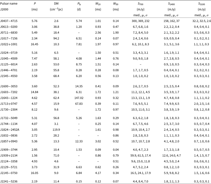
Table 1. Fundamental parameters of the PPTA DR2 pulsars, including pulse period (P), dispersion measure (DM), and orbital period ( $P_{\rm b}$
). Pulse widths are derived from the mean pulse profile and are given for the 10% and 50% levels (
$P_{\rm b}$
). Pulse widths are derived from the mean pulse profile and are given for the 10% and 50% levels ( $W_{10}$
and
$W_{10}$
and  $W_{50}$
, respectively) relative to the observed pulse peak. Flux densities (
$W_{50}$
, respectively) relative to the observed pulse peak. Flux densities ( $S_f$
for centre frequency f) are represented by their median (med.), mean (
$S_f$
for centre frequency f) are represented by their median (med.), mean ( $\mu$
), and standard deviation estimate (
$\mu$
), and standard deviation estimate ( $\sigma$
, defined as half of the range between the 84th percentile flux and the 16th percentile flux), which were derived from the distributions of fluxes measured with the latest observing systems.
$\sigma$
, defined as half of the range between the 84th percentile flux and the 16th percentile flux), which were derived from the distributions of fluxes measured with the latest observing systems.
Timing array experiments rely on long-term timing observations of millisecond pulsars in which the various noise processes can be accurately modelled (Coles et al. Reference Coles, Hobbs, Champion, Manchester and Verbiest2011; van Haasteren & Levin Reference van Haasteren and Levin2013; Lentati et al. Reference Lentati, Alexander, Hobson, Feroz, van Haasteren, Lee and Shannon2014). For instance, dispersion measure (DM) variations can dominate timing residuals if multi-band observations are not available (see, e.g., Keith et al. Reference Keith2013). This implies that, to be useful for the PPTA experiment, a pulsar must be sufficiently bright to obtain precise ToAs in at least two of the three observing bands. It may be possible to correct for DM variations within individual bands of sufficient fractional bandwidth (Verbiest & Shaifullah Reference Verbiest and Shaifullah2018), which may have advantages to multi-band observations (Pennucci, Demorest, & Ransom Reference Pennucci, Demorest and Ransom2014; Cordes, Shannon, & Stinebring Reference Cordes, Shannon and Stinebring2016).
A summary of the pulsars in this data release is given in Table 1. This table contains the pulse periods, DMs, orbital periods, mean pulse widths for the 20-cm band profile at 10% and 50% of the profile peak, and mean flux densities in the 40, 20, and 10 cm observing bands averaged over the available data span. Because of interstellar scintillation, observed flux densities vary from day to day, often by large factors. The quoted values are long-term averages, and we estimate that their systematic error is less than a few percent.
During observing sessions, three types of observations are conducted. The primary data product is pulsar fold-mode data. Immediately prior to each of these, we observe a pulsed noise diode, which is used for the calibration (see Section 3.2). This observation is slightly offset from the pulsar position to prevent the pulsar signal from contributing excess noise (which is particularly important for  $\text{PSR\ J}0437{-}4715$
). For some of the pulsars with the most accurate arrival times, we also record the noise source after the observation, which enables interpolation of the calibration solution across the observation to correct for drifts. During most observing sessions, we also observe the radio galaxy Hydra A (PKS
$\text{PSR\ J}0437{-}4715$
). For some of the pulsars with the most accurate arrival times, we also record the noise source after the observation, which enables interpolation of the calibration solution across the observation to correct for drifts. During most observing sessions, we also observe the radio galaxy Hydra A (PKS  $0915{-}11$
) as a primary flux density calibrator. The ‘raw’ (uncalibrated) data files are available from the Parkes data archive (available from data.csiro.au; see Hobbs et al. Reference Hobbs2011)Footnote d. Each observation was taken as part of an observing project that had a unique identifier. By far, the majority of the observations were obtained as part of the formal PPTA project (P456), but a significant number were obtained as part of two other projects. P140 was an observing project to carry out high-precision timing of millisecond pulsars in the 20-cm observing band and preceded the PPTA commencement. P895 was started in order to carry out high-cadence observations of
$0915{-}11$
) as a primary flux density calibrator. The ‘raw’ (uncalibrated) data files are available from the Parkes data archive (available from data.csiro.au; see Hobbs et al. Reference Hobbs2011)Footnote d. Each observation was taken as part of an observing project that had a unique identifier. By far, the majority of the observations were obtained as part of the formal PPTA project (P456), but a significant number were obtained as part of two other projects. P140 was an observing project to carry out high-precision timing of millisecond pulsars in the 20-cm observing band and preceded the PPTA commencement. P895 was started in order to carry out high-cadence observations of  $\text{PSR\ J}1909{-}3744$
in the 10-cm observing band. Some data were taken as part of project P865, which commensally searched for fast radio bursts while monitoring PPTA pulsars (see Osłowski et al. 2019). The data collection identifies from which project each observation belongs. We use the Psrfits data format (Hotan et al. Reference Hotan, van Straten and Manchester2004) which stores pulsar data along with observational metadata in binary Flexible Image Transport System tables.
$\text{PSR\ J}1909{-}3744$
in the 10-cm observing band. Some data were taken as part of project P865, which commensally searched for fast radio bursts while monitoring PPTA pulsars (see Osłowski et al. 2019). The data collection identifies from which project each observation belongs. We use the Psrfits data format (Hotan et al. Reference Hotan, van Straten and Manchester2004) which stores pulsar data along with observational metadata in binary Flexible Image Transport System tables.
The observing strategy (see Figure 1) evolved as new pulsars were added to the array and as the RFI environment changed. The fraction of the band that is clear is evolving with time, as terrestrial use of the band increases (e.g., mobile handsets) and more satellites are launched that use the 20-cm band for transmission (e.g., global navigation satellite systems). For the data presented here, the primary strategy was to observe a pulsar in a given band for  $\sim$
5 min. At this point, the pulsar profile was inspected by eye. If the pulsar was in a low scintillation state, or if the RFI was much stronger than typical, then the observation would be stopped and a new pulsar (or a new observing band) chosen. The initial pulsar would be re-observed after an interval greater than the diffractive timescale (see, e.g., You et al. Reference You2007) had elapsed.
$\sim$
5 min. At this point, the pulsar profile was inspected by eye. If the pulsar was in a low scintillation state, or if the RFI was much stronger than typical, then the observation would be stopped and a new pulsar (or a new observing band) chosen. The initial pulsar would be re-observed after an interval greater than the diffractive timescale (see, e.g., You et al. Reference You2007) had elapsed.

Figure 1. The PPTA observing cadence. The three observing bands (10, 20, and 40/50 cm) are shown in blue, cyan, and red respectively, while the legacy 20-cm observations are shown in black.
Each pulsar is typically observed every 2 to 3 weeks. In Figure 1, we show the observing cadence in the three observing bands. The first PPTA data release included an extended version (known as ‘DR1e’) with pre-2004 legacy 20-cm data included, based on a data set published in Verbiest et al. (Reference Verbiest2009). We have not re-processed these earlier observations for DR2, but if the longer data spans are required then these observations can be obtained from the M+13 data collection. These earlier observations are not used for any of the subsequent work described in this paper, but their cadence is shown in Figure 1.
As new pulsars are added into the PPTA sample, the existing sample is inspected to see whether any pulsars should be removed.  $\text{PSR\ J}1732{-}5049$
was regularly observed from 2005 December to 2011 May, but the very wide pulse profile leads to relatively imprecise ToA measurements with typical uncertainties of 1 to 3
$\text{PSR\ J}1732{-}5049$
was regularly observed from 2005 December to 2011 May, but the very wide pulse profile leads to relatively imprecise ToA measurements with typical uncertainties of 1 to 3  $\mu\text{s}$
. The pulsar was subsequently removed from the array, but may be of interest for timing programmes on future high-gain southern hemisphere telescopes, such as MeerKAT (Bailes et al. Reference Bailes2016) and the Square Kilometre Array (SKA; Janssen et al. Reference Janssen2015; Keane 2018).
$\mu\text{s}$
. The pulsar was subsequently removed from the array, but may be of interest for timing programmes on future high-gain southern hemisphere telescopes, such as MeerKAT (Bailes et al. Reference Bailes2016) and the Square Kilometre Array (SKA; Janssen et al. Reference Janssen2015; Keane 2018). $\text{PSR\ J}1832{-}0836$
has been observed with modest cadence since 2013 June. It is relatively faint at both 10 and 40 cm; consequently, DM variation correction is difficult. However, root-mean-square (rms) residuals below 1
$\text{PSR\ J}1832{-}0836$
has been observed with modest cadence since 2013 June. It is relatively faint at both 10 and 40 cm; consequently, DM variation correction is difficult. However, root-mean-square (rms) residuals below 1  $\mu\text{s}$
can still be achieved, owing to a profile with three narrow components, and consequently, the PPTA observes this pulsar, but, until the advent of the UWL receiver, only in the 20-cm observing band. These data can be combined with multi-band IPTA data, observed as part of the NANOGrav project (Arzoumanian et al. Reference Arzoumanian2018b).
$\mu\text{s}$
can still be achieved, owing to a profile with three narrow components, and consequently, the PPTA observes this pulsar, but, until the advent of the UWL receiver, only in the 20-cm observing band. These data can be combined with multi-band IPTA data, observed as part of the NANOGrav project (Arzoumanian et al. Reference Arzoumanian2018b).
Although it is an interesting source for the study of the solar wind (see, e.g., You et al. Reference You, Coles, Hobbs and Manchester2012) and globular cluster dynamics,  $\text{PSR\ J}1824{-}2452\text{A}$
boasts some of the largest timing and DM variation noise levels of any millisecond pulsar and is observed only with low priority. Following the first release of PPTA data, five new pulsars have been added to the array as itemised below. Average pulse profiles for the new pulsars were analysed and published in Dai et al. (Reference Dai2015), with the exception of the profile of
$\text{PSR\ J}1824{-}2452\text{A}$
boasts some of the largest timing and DM variation noise levels of any millisecond pulsar and is observed only with low priority. Following the first release of PPTA data, five new pulsars have been added to the array as itemised below. Average pulse profiles for the new pulsars were analysed and published in Dai et al. (Reference Dai2015), with the exception of the profile of  $\text{PSR\ J}1125{-}6014$
, shown in Figure 2.
$\text{PSR\ J}1125{-}6014$
, shown in Figure 2. $\text{PSR\ J}1017{-}7156$
has a narrow pulse width allowing for precise ToAs to be determined (particularly in the 20 -cm observing band). Its discovery was presented in Keith et al. (Reference Keith2012) in the High Time Resolution Universe Parkes pulsar survey and has been observed since 2010 July.
$\text{PSR\ J}1017{-}7156$
has a narrow pulse width allowing for precise ToAs to be determined (particularly in the 20 -cm observing band). Its discovery was presented in Keith et al. (Reference Keith2012) in the High Time Resolution Universe Parkes pulsar survey and has been observed since 2010 July.-
$\text{PSR\ J}1125{-}6014$
was found in the Parkes Mulitbeam Pulsar Survey (Lorimer et al. Reference Lorimer2006) and timed at 20 cm only in a dedicated follow-up programme (P501) and a general-purpose binary pulsar timing campaign (P789) from 2005 December. Multi-band PPTA observations commenced in 2014 July.
-
$\text{PSR\ J}1446{-}4701$
, discovered by Keith et al. (2012), is a
$\gamma$
-ray pulsar that has been observed since Reference Keith2011 November. It is a black widow system with a 6.7-h orbit.
-
$\text{PSR\ J}1545{-}4550$
(Burgay et al. Reference Burgay2013) has been recorded with 20-cm coverage since 2011 May and multi-wavelength PPTA coverage from 2012 February.
-
$\text{PSR\ J}2241{-}5236$
was discovered in a targeted search of Fermi
$\gamma$
-ray sources by Keith et al. (Reference Keith2011). Early multi-wavelength observations in a variety of programmes commenced in 2010 February, and regular PPTA observations commenced in 2010 August.
$\text{PSR\ J}2241{-}5236$
could be classified as a black widow system (although it shows no evidence of eclipse) with a 3.5-h orbital period and an extremely light (
$\sim\!0.011{\rm M}_\odot$
) companion. As discussed below, the pulsar shows orbit-induced timing variations.


3. The data processing pipeline
One of the primary aims of this data release is to ensure a transparent processing of the raw data into the final ToA products. We start from an archive of the raw data and provide a description of all steps undertaken in the analysis and in producing the reduced data. We do this through the use of psrsh, a domain-specific language for the psrchive packageFootnote e. psrsh is a simple, human-readable set of commands that describe a data reduction pipeline. The goal of our processing pipeline is thus to create optimal psrsh scripts. An example of such a script (and how it is used) is given in Appendix A.
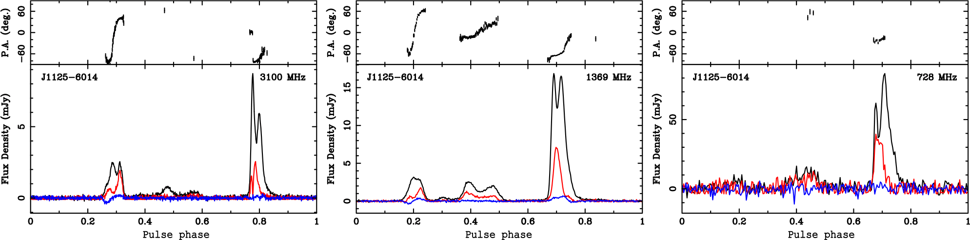
Figure 2. Pulse profiles in the 10-cm (left), 20 cm (central), and 40/50 cm (right) observing bands for  $\text{PSR\ J}1125{-}6014$
. For each observing band, we show the total intensity profile in black, the linear polarisation in red, and the circular polarisation in blue. The position angle of the linear polarisation is shown in the top subpanel.
$\text{PSR\ J}1125{-}6014$
. For each observing band, we show the total intensity profile in black, the linear polarisation in red, and the circular polarisation in blue. The position angle of the linear polarisation is shown in the top subpanel.
The pipeline code is implemented in Python and, together with ancillary text files, is available as open source softwareFootnote f. In the following subsections, we describe the principal components of the data processing pipeline.
3.1. RFI mitigation
The RFI environment at Parkes is surprisingly good, given that many licensed transmitters exist within the bands used for radio astronomy. However, RFI is present in nearly all PPTA data. In this subsection, we give a brief overview of the interference environment and the mitigation steps that we have taken.
In mid-2009, as described in M+13, concern over digital television transmissions resulted in the 64-MHz 50-cm band, previously centred at 685 MHz, being moved to 732 MHz and hence renamed as the 40-cm band. After this move, the band was relatively clean apart from various relatively narrow band transmissions which were excised using the psrchive median bandpass filter implemented in the routine paz. For a number of years, the band became cleaner as analogue television broadcasts were phased out.
In 2015 April, a 4G mobile phone transmitter in the band 758–768 MHz began operation in Alectown, New South Wales, about 10 km north of the telescope. These signals were sufficiently bright to introduce substantial system non-linearities. To mitigate this, in 2015 May, we moved the centre frequency to 724 MHz, despite this resulting in a somewhat suboptimal bandpass. There is also occasional in-band RFI associated with 4G mobile phone handsets in the band 703–733 MHz. We excise affected sub-integrations that survive the spectral kurtosis and median bandpass filtering. Occasionally, most of the band is zero-weighted, and we discard such observations completely.
Within the nominal  $256{-}350\,\text{MHz}$
bandwidths of the 20-cm systems, the band is relatively free from RFI during most observations. There is a narrow band microwave link operating around 1 450 MHz (1 440 MHz prior to MJD
$256{-}350\,\text{MHz}$
bandwidths of the 20-cm systems, the band is relatively free from RFI during most observations. There is a narrow band microwave link operating around 1 450 MHz (1 440 MHz prior to MJD $\sim$
55000) which we excise with the median bandpass filter. The most destructive source of RFI is the episodic occurrence of aircraft radar, which can persist for several hours and, when strong, produces non-linearities in the low-noise amplifiers. During the presence of the radar, observers typically switch to the dual-band 10/40 cm system. However, we discard observations that are badly affected by the interference. More recently, and with higher cadence, RFI from satellites, particularly those of the Beidou, COMPASS, and Galileo global positioning system (GPS) constellations have affected our observations. When these satellites pass through far sidelobes of the telescope beam, they contaminate their
$\sim$
55000) which we excise with the median bandpass filter. The most destructive source of RFI is the episodic occurrence of aircraft radar, which can persist for several hours and, when strong, produces non-linearities in the low-noise amplifiers. During the presence of the radar, observers typically switch to the dual-band 10/40 cm system. However, we discard observations that are badly affected by the interference. More recently, and with higher cadence, RFI from satellites, particularly those of the Beidou, COMPASS, and Galileo global positioning system (GPS) constellations have affected our observations. When these satellites pass through far sidelobes of the telescope beam, they contaminate their  $\sim$
60 MHz bandwidth, but when they pass near the main beam, they result in non-linearities. We also discard these latter observations.
$\sim$
60 MHz bandwidth, but when they pass near the main beam, they result in non-linearities. We also discard these latter observations.
Finally, the 10-cm system has been largely free from RFI and an automatic median bandpass filter suffices to remove most instances. Since mid-2015, several 20 MHz-wide channels associated with mobile phone and data transmission licenses have become active. The transmission strength has varied with date and with telescope position, and we have tabulated the affected observations to remove the appropriate channel range.
Pipeline deletion or flagging of RFI is under control of ‘rule sets’ which specify the frequencies and/or times affected by RFI for each observation and the mitigation method. For illustration, part of an RFI mitigation rule set is shown in Appendix B.
3.2. Calibration methods
To calibrate the system, we make use of a noise diode cycled at 11.123 Hz and injected into the signal path for each polarisation, normally into the feed horn at  $45^\circ$
to each signal probe. This is used to calibrate the differential gain and phase of the two signal paths and, with observations of the flux density calibrator (Hydra A), the equivalent flux density of both the calibration signal and the system. See M+13 for a full description of the calibration system and the operational procedures for polarisation and flux density calibration.
$45^\circ$
to each signal probe. This is used to calibrate the differential gain and phase of the two signal paths and, with observations of the flux density calibrator (Hydra A), the equivalent flux density of both the calibration signal and the system. See M+13 for a full description of the calibration system and the operational procedures for polarisation and flux density calibration.
In Figure 3, we provide details of how the calibration equivalent flux densities and the system equivalent flux densities (SEFD) values vary in time and frequency for the different observing systems. Step changes in SEFD spectra occurred when one or more parts of the receiver system were modified. For example, on 2006 June 21 (MJD 53907), the PDFB1 signal path was modified to improve linearity; 20-cm SEFD measurements prior to this date are unreliable. Since the calibration source for a given system shows only modest (few per cent) long-term variations, we have averaged individual measurements over 6-month intervals (unless a step change occurred during this period) to increase the signal-to-noise ratio (S/N) and to minimise small systematic errors and the number of channels given zero weight because of RFI. The specific flux density calibrator observations used for these averages are available as lists accompanying the pipeline code.
So far, we have discussed a calibration procedure sufficient for an ideal system. Real systems depart from this ideal and may show substantial levels of cross-polarisation, feed non-orthogonality, and differential sensitivity. We follow the method of van Straten (Reference van Straten2004) as implemented in the psrchive routine pcm and applied to long observations of  $\text{PSR\ J}0437{-}4715$
with most combinations of receivers and signal processors. The main results are in Figure 4, where we show the ellipticities of the receiver system (
$\text{PSR\ J}0437{-}4715$
with most combinations of receivers and signal processors. The main results are in Figure 4, where we show the ellipticities of the receiver system ( $\epsilon_0$
and
$\epsilon_0$
and  $\epsilon_1$
) as well as the orientation of receptor 1 with respect to receptor 0 (
$\epsilon_1$
) as well as the orientation of receptor 1 with respect to receptor 0 ( $\theta_1$
). In brief, the 20-cm H-OH feed and the co-axial 40/50 cm plus 10-cm feed are close to the ideal over most of their bands. The 20-cm multi-beam system shows substantial non-orthogonality and cross-polarisation. Consequently, for the 20-cm multibeam system, we apply the full receiver model. As with the flux calibration solutions, we expect the system properties to be intrinsic to the hardware and to change only slowly, if at all, and so we combine observations to form an average solution. For all other observing systems, we simply apply the differential gain and bandpass calibration as described above.
$\theta_1$
). In brief, the 20-cm H-OH feed and the co-axial 40/50 cm plus 10-cm feed are close to the ideal over most of their bands. The 20-cm multi-beam system shows substantial non-orthogonality and cross-polarisation. Consequently, for the 20-cm multibeam system, we apply the full receiver model. As with the flux calibration solutions, we expect the system properties to be intrinsic to the hardware and to change only slowly, if at all, and so we combine observations to form an average solution. For all other observing systems, we simply apply the differential gain and bandpass calibration as described above.

Figure 3. Variations of noise source equivalent flux density (left panels) and SEFD (right panels) as functions of time and frequency for the 10-cm band (top), 20-cm band (middle), and 40-cm band (bottom) based on observations of Hydra-A. The colour bar indicates the equivalent flux density in fiducial units (Jy) in each case. Signal processors used were PDFB2 and PDFB4 for 10 cm, PDFB1, PDFB2 and PDFB4 for 20 cm, and PDFB3 for 40 cm. Individual measurements have been interpolated on to a grid for display.

Figure 4. Modelled receiver polarisation parameters  $\epsilon_0$
(red),
$\epsilon_0$
(red),  $\epsilon_0$
(blue), and
$\epsilon_0$
(blue), and  $\theta_1$
(black). Left: the 10-cm system using PDFB4. Centre: the 20-cm multi-beam system using PDFB4. Right: the 40-cm system using PDFB3. The H-OH receiver is not displayed because it shows no evidence for feed cross-coupling.
$\theta_1$
(black). Left: the 10-cm system using PDFB4. Centre: the 20-cm multi-beam system using PDFB4. Right: the 40-cm system using PDFB3. The H-OH receiver is not displayed because it shows no evidence for feed cross-coupling.
For  $\text{PSR\ J}0437{-}4715$
, by far the brightest millisecond pulsar, and with emission extending over 90% of the pulse period and rapidly changing polarisation properties (Dai et al. Reference Dai2015), we find substantial profile variation remains after polarisation calibration. We therefore follow the same approach as in DR1 and, for
$\text{PSR\ J}0437{-}4715$
, by far the brightest millisecond pulsar, and with emission extending over 90% of the pulse period and rapidly changing polarisation properties (Dai et al. Reference Dai2015), we find substantial profile variation remains after polarisation calibration. We therefore follow the same approach as in DR1 and, for  $\text{PSR\ J}0437{-}4715$
, form the invariant interval (Britton Reference Britton2000), which reduces the dependence on polarisation calibration.
$\text{PSR\ J}0437{-}4715$
, form the invariant interval (Britton Reference Britton2000), which reduces the dependence on polarisation calibration.
Following calibration (again carried out within the psrsh scripts), a variety of processing tasks can be performed. Typical output products include calibrated data with various levels of frequency, time, and polarisation averaging and dynamic spectra matched-filtered with the average pulse profile. The most important for present purposes is the formation of ToA measurements for each pulsar—this is described in detail in Section 4 below.
3.3. Identification and correction of instrumental problems
Over the long observing programme, various systematic issues have been identified in the data set. As a sample of such problems:
Observations when digitiser levels are set incorrectly resulting in clipping or compression.
Observations with polarisation inputs swapped.
Commissioning of new instruments.
Periods when the observatory maser was unreliable.
Observations with satellite passages through sidelobes near the primary beam.
Observations where the line of sight to the pulsar passes close to the Sun.
During the commissioning of various signal processor systems, metadata were occasionally missing or written out incorrectly. Instances where these values are incorrect or missing have been formulated both as rule sets (e.g., date ranges with known clock failures) or as annotated individual listings of observations (e.g., for satellite passages). During processing, these lists and rules are ingested to provide guidance for processing (e.g., zero-weighted RFI-affected sub-integrations) or to propagate data quality flags to the final data products. We note that observations with unreliable timing may still be useful for some astrophysical analysis.
3.4. Instrumental timing offsets
There are generally unknown signal delays associated with each instrument. These reflect the signal path delay and, for some instruments, the particular scheme employed for time tagging. For example, until firmware changes on MJD 55319 were implemented, the delays of the Wide-band correlator (WBCORR) and PDFB instruments depended on the configuration of the filterbank (bandwidth, number of channels, and number of pulse phase bins) because of the configuration-dependent delays through the field-programmable gate array processors (for the digital filterbanks). The firmware changes instead allowed time stamping at the digitiser and delays that in principle depend only on the signal path.
We have conducted a study of the delays measured and used within M+13 and found that the vast majority are accurate to the level required in our analysis (a few tens of nanoseconds). We have also identified new delays associated with bandpass changes and saturation effects that can affect pulse profile shapes, but they are small and difficult to separate from other sources of delay change. While M+13 applied corrections for these (and other) delays directly to the pulse profile metadata, we have opted to record them as tempo2 JUMP parameters, with each observation receiving the appropriate flag(s) to trigger a JUMP/delay when appropriate. This approach both makes the delay corrections more obvious and allows easier modification for values found to be in error. The complete list of the fixed and floating offsets for an example pulsar is given in Appendix C.
4. The PPTA DR2 timing data Set
The PPTA DR2 data set contains pulse ToAs for each of the pulsars listed in Table 1. These ToAs are referenced to the local observatory time system through the time-tagging mechanisms implemented in the various signal processors. The Observatory clock and the associated 1-s pulse (1PPS) are derived from a 5-MHz reference signal locked to a hydrogen maser frequency standard, currently a Vremya VCH-1005A unit. This 5-MHz reference is also used to lock all local oscillators and digitiser samplers used at the Observatory. The maser is located in an air-conditioned enclosure about 100 m east of the telescope. The phase of the 1PPS is monitored using a GPS clock, currently a Symmetricom XL-GPS unit, located in the telescope tower, with an antenna  $\sim$
50 m east of the telescope.Footnote g The offset between the Observatory 1PPS and the GPS 1PPS is recorded at 5-min intervals and used to form the required clock correction files. In order to maintain the Observatory 1PPS within a microsecond or so of the GPS reference, the maser is steered with rate and/or step changes. Step changes generally only occur after a system failure or transition, but rate changes to compensate for instabilities in the maser reference frequency are made more frequently, typically every few weeks. There are diurnal variations of order 10 ns amplitude in the measured offset due to atmospheric and ionospheric variations. For pulsar timing, we use daily averages of the offset to smooth over this diurnal variation, giving an estimated accuracy in the reference time of a few nanoseconds. The clock correction chain used by tempo2 to transfer the ToA reference from the Observatory clock to TT(BIPM18) is UTC(PKS)
$\sim$
50 m east of the telescope.Footnote g The offset between the Observatory 1PPS and the GPS 1PPS is recorded at 5-min intervals and used to form the required clock correction files. In order to maintain the Observatory 1PPS within a microsecond or so of the GPS reference, the maser is steered with rate and/or step changes. Step changes generally only occur after a system failure or transition, but rate changes to compensate for instabilities in the maser reference frequency are made more frequently, typically every few weeks. There are diurnal variations of order 10 ns amplitude in the measured offset due to atmospheric and ionospheric variations. For pulsar timing, we use daily averages of the offset to smooth over this diurnal variation, giving an estimated accuracy in the reference time of a few nanoseconds. The clock correction chain used by tempo2 to transfer the ToA reference from the Observatory clock to TT(BIPM18) is UTC(PKS) $\rightarrow$
UTC(GPS)
$\rightarrow$
UTC(GPS) $\rightarrow$
TT(TAI)
$\rightarrow$
TT(TAI) $\rightarrow$
TT(BIPM18). TT(TAI)-UTC(GPS) is obtained from Circular T of the BIPM and the post-corrected timescales TT(BIPMxx)-TT(TAI), where xx is the year (20xx), are published annually by the BIPM—see Arias & Petit (Reference Arias and Petit2019) for a recent discussion of reference timescales.
$\rightarrow$
TT(BIPM18). TT(TAI)-UTC(GPS) is obtained from Circular T of the BIPM and the post-corrected timescales TT(BIPMxx)-TT(TAI), where xx is the year (20xx), are published annually by the BIPM—see Arias & Petit (Reference Arias and Petit2019) for a recent discussion of reference timescales.
We provide two arrival time files for each pulsar: (1) a single ToA for each observation in a given receiver band where the data have been summed over frequency, and (2) multiple ToAs for sub-bands within a given band for each observation. The number of sub-bands was dynamically chosen based on the S/N of the profile and ranges from 2 to 32 for different observations and bands. Sub-banded arrival times are especially important for pulsars whose pulse profile evolves strongly with frequency. Any induced variations in the centre frequency (either related to a varying RFI environment or diffractive scintillation) can add substantial measurement noise when averaging over the observing band to produce ToAs.
ToAs were obtained from the calibrated profiles using a standard template for each receiver and band with the psrchive routine pat implementing the Taylor (Reference Taylor and Backer1990) algorithm. We would expect to get comparable results with the Monte Carlo-based Fourier-domain Monte Carlo algorithm, given the typical high S/N of the observations. The standard templates were formed from the sum of Von Mises functions, as described in M+13, with a single frequency-averaged template used for each band. ToAs for a given pulsar obtained with different templates will have a floating offset (a ‘jump’) indicated in the corresponding parameter files. These jumps are measured with respect to PDFB4 data in the 10-cm observing band. This band and system was chosen as the reference because it provides the highest precision timing for the best pulsars. The templates were approximately aligned manually and so the offsets are expected to be relatively small. The ToAs are matched with the output from the processing pipeline to furnish estimates of the signal-to-noise ratio (S/N), goodness-of-fit, and any observation flags. This output is incorporated directly into the tempo2 ToA output file (see Appendix D).
The pipeline produces band-averaged and sub-banded ToAs for each observation. However, it is often desirable to select for or against certain groups of ToAs for particular applications. This is achieved through the use of the tempo2 flags associated with each ToA. For this data release, we select ToAs suitable for high-precision timing purposes using tempo2 ‘select’ files. An example select file is given along with further details of their use in Appendix E. For the data collection provided with this paper, we have already applied these select files.
PPTA observations are often made with multiple signal processor systems. This is helpful in determining the instrumental time offsets between the different systems and in detection of any inconsistencies. For the data release, we provide only one set of ToAs for each observation, in general, those from the most up-to-date observing instrument.
Table 2 lists the pulsar name, observing band, MJDs of the first and last observations, the overall data span, the total integration time, the number of ToAs in the band-averaged data, and the mean and median ToA uncertainties (as directly measured from the observations without noise modelling). The final three columns provide the number of sub-banded ToAs and their corresponding mean and median uncertainty.
Table 2. Observational properties of the PPTA data release.

Note: Int. Time is the total integration time.  $N_{ToA,sb}$
is the number of sub-banded ToAs in each data set.
$N_{ToA,sb}$
is the number of sub-banded ToAs in each data set.
For each pulsar, we determine initial noise models using the EnterpriseFootnote h package (Ellis et al. Reference Ellis, Vallisneri, Taylor and Baker2017), to account for any low-frequency (‘red’) noise in the residuals. These noise models include a simple power law for frequency-independent red noise, such as intrinsic spin variations, as well as a frequency-dependent power law with  $\nu^{-2}$
scaling to account for DM variations, where
$\nu^{-2}$
scaling to account for DM variations, where  $\nu$
is the radio frequency. These power laws were fitted to the data as the amplitudes of sine-cosine Fourier component pairs, with frequencies
$\nu$
is the radio frequency. These power laws were fitted to the data as the amplitudes of sine-cosine Fourier component pairs, with frequencies  $k/T_{\rm span}$
, where
$k/T_{\rm span}$
, where  $k=1,\dots,N$
for N components, and
$k=1,\dots,N$
for N components, and  $T_{\rm span}$
is the total observing span. The number of Fourier components N was chosen for each pulsar such that the highest frequency modelled,
$T_{\rm span}$
is the total observing span. The number of Fourier components N was chosen for each pulsar such that the highest frequency modelled,  $N/T_{\rm span}$
was equivalent to
$N/T_{\rm span}$
was equivalent to  $1/60$
d. Lower frequency red noise is absorbed into the spin frequency and spin-down parameters. Note that the first and second time derivatives of DM were also included in the timing model for all pulsars, in order to pre-whiten any DM variations. Additional band-dependent noise models were required for PSRs
$1/60$
d. Lower frequency red noise is absorbed into the spin frequency and spin-down parameters. Note that the first and second time derivatives of DM were also included in the timing model for all pulsars, in order to pre-whiten any DM variations. Additional band-dependent noise models were required for PSRs  $\text{J}0437{-}4715$
and J1939+2134 (see Lentati et al. Reference Lentati2016). The exponential DM events observed in PSR
$\text{J}0437{-}4715$
and J1939+2134 (see Lentati et al. Reference Lentati2016). The exponential DM events observed in PSR  $\text{J}1713+0747$
(Lam et al. Reference Lam2018) and the magnetospheric event observed in
$\text{J}1713+0747$
(Lam et al. Reference Lam2018) and the magnetospheric event observed in  $\text{PSR\ J}1643{-}1224$
(shown in Figure 6; Shannon et al. Reference Shannon2016) were modelled as chromatic exponential functions using Enterprise simultaneously with noise parameters, and then included into the timing model using extra parameters. The contribution to the timing residuals is modelled to be
$\text{PSR\ J}1643{-}1224$
(shown in Figure 6; Shannon et al. Reference Shannon2016) were modelled as chromatic exponential functions using Enterprise simultaneously with noise parameters, and then included into the timing model using extra parameters. The contribution to the timing residuals is modelled to be
 \begin{equation}R(t) = \theta(t-t_0) A \left( \frac{\nu}{1.4\,{\rm GHz}} \right)^\alpha \exp \left( - \frac{t-t_0}{\tau} \right),\end{equation}
where  $\theta(t)$
is the Heaviside (step) function,
$\theta(t)$
is the Heaviside (step) function,  $t_0$
is the epoch of the event, A its amplitude in
$t_0$
is the epoch of the event, A its amplitude in  $\mu\text{s}$
,
$\mu\text{s}$
,  $\tau$
is the decay timescale in days, and
$\tau$
is the decay timescale in days, and  $\alpha$
is the spectral index of the frequency scaling (e.g.,
$\alpha$
is the spectral index of the frequency scaling (e.g.,  $\alpha =-2$
for DM-like events and
$\alpha =-2$
for DM-like events and  $\alpha =0$
for achromatic events). The exponential fitting function is chosen as it phenomenologically matches the function in the arrival times (Shannon et al. Reference Shannon2016; Desvignes et al. Reference Desvignes2016). These fitting functions have been incorporated into the tempo2 repository.
$\alpha =0$
for achromatic events). The exponential fitting function is chosen as it phenomenologically matches the function in the arrival times (Shannon et al. Reference Shannon2016; Desvignes et al. Reference Desvignes2016). These fitting functions have been incorporated into the tempo2 repository.
To account for pulse profile evolution with radio frequency, our parameter files also include ‘FD’ parameters for all pulsars except PSRs  $\text{J}1446{-}4701$
and
$\text{J}1446{-}4701$
and  $\text{J}1832{-}0836$
. These parameters are the coefficients of a polynomial function fitted to the logarithm of observing frequency (Arzoumanian et al. Reference Arzoumanian2015). The number of FD parameters was determined using the Akaike information criterion (AIC; Akaike Reference Akaike1998).
$\text{J}1832{-}0836$
. These parameters are the coefficients of a polynomial function fitted to the logarithm of observing frequency (Arzoumanian et al. Reference Arzoumanian2015). The number of FD parameters was determined using the Akaike information criterion (AIC; Akaike Reference Akaike1998).
For  $\text{PSR\ J}0437{-}4715$
, we identified an inconsistency in the apparent pulse profile evolution for some early observing systems (CPSR2, PDFB1, and WBCORR) relative to newer systems. We attribute this to frequency- and phase-dependent sensitivity changes, rather than intrinsic profile evolution. These system-induced profile evolution components are the most significant for
$\text{PSR\ J}0437{-}4715$
, we identified an inconsistency in the apparent pulse profile evolution for some early observing systems (CPSR2, PDFB1, and WBCORR) relative to newer systems. We attribute this to frequency- and phase-dependent sensitivity changes, rather than intrinsic profile evolution. These system-induced profile evolution components are the most significant for  $\text{PSR\ J}0437{-}4715$
because of its brightness. For this pulsar, we measured the FD parameters relative to stable system (PDFB3, PDFB4, and CASPSR), for all observing bands. The excess apparent profile evolution in the early systems was then measured relative to these by fitting a polynomial (with order up to a cubic function, as determined by the AIC), as a function of frequency. This offset was then subtracted directly from the ToAs.
$\text{PSR\ J}0437{-}4715$
because of its brightness. For this pulsar, we measured the FD parameters relative to stable system (PDFB3, PDFB4, and CASPSR), for all observing bands. The excess apparent profile evolution in the early systems was then measured relative to these by fitting a polynomial (with order up to a cubic function, as determined by the AIC), as a function of frequency. This offset was then subtracted directly from the ToAs.
For  $\text{PSR\ J}2241{-}5236$
, we also included six orbital frequency derivatives in the timing model to account for observed variations in the orbital period. These additional parameters are not expected to significantly reduce the sensitivity of the observations to low-frequency GWs (Bochenek, Ransom, & Demorest Reference Bochenek, Ransom and Demorest2015). We note that a detailed analysis of noise models for DR2 pulsars will be presented elsewhere. These initial models are used here simply to ensure the integrity of our ToAs and to allow for initial fitting of the system jump parameters.
$\text{PSR\ J}2241{-}5236$
, we also included six orbital frequency derivatives in the timing model to account for observed variations in the orbital period. These additional parameters are not expected to significantly reduce the sensitivity of the observations to low-frequency GWs (Bochenek, Ransom, & Demorest Reference Bochenek, Ransom and Demorest2015). We note that a detailed analysis of noise models for DR2 pulsars will be presented elsewhere. These initial models are used here simply to ensure the integrity of our ToAs and to allow for initial fitting of the system jump parameters.
For the figures described below, we have formed residuals from the sub-banded ToAs and then averaged (with weighting) the resulting residuals for each observing system for each observation. This enables us to account for profile evolution in the fitting, but also to see weak signals that would be difficult to identify in a single sub-banded observation. In Figure 5, we show band-averaged timing residuals for the PPTA DR2 pulsars before fitting for DM variations and frequency-independent red noise. For many pulsars, there are large systematic residuals resulting from DM variations and/or frequency-independent timing noise. The quoted weighted rms residuals reflect these systematic variations. Note that an apparent offset in the low-frequency (red, 40, and 50 cm) residuals for  $\text{PSR\ J}0437{-}4715$
corresponds to the mid-2009 change in the centre frequency of this band and is caused by the
$\text{PSR\ J}0437{-}4715$
corresponds to the mid-2009 change in the centre frequency of this band and is caused by the  $\nu^{-2}$
scaling of the DM variations.
$\nu^{-2}$
scaling of the DM variations.
Timing residuals as in Figure 5, but after the best-fitting DM variations have been removed, are shown in Figure 6. This figure highlights the frequency-independent timing noise present in the residuals for some pulsars, for example,  $\text{PSR\ J}1824{-}2452$
A. However, band-dependent noise still appears to be present in some pulsars, for example, PSR J1939+2134, where the 40-cm residuals show some features not accounted for DM modelling. These deviations may result from changes in the amount of interstellar scattering modifying the 40-cm profile shape (Coles et al. Reference Coles2015). We note the fitting incorporates a generalised least-square algorithm to account for both DM variations and achromatic timing noise. This fitting method will reveal quadratic features in the timing residuals that would be absorbed in a simple weighted least-squares fit.
$\text{PSR\ J}1824{-}2452$
A. However, band-dependent noise still appears to be present in some pulsars, for example, PSR J1939+2134, where the 40-cm residuals show some features not accounted for DM modelling. These deviations may result from changes in the amount of interstellar scattering modifying the 40-cm profile shape (Coles et al. Reference Coles2015). We note the fitting incorporates a generalised least-square algorithm to account for both DM variations and achromatic timing noise. This fitting method will reveal quadratic features in the timing residuals that would be absorbed in a simple weighted least-squares fit.
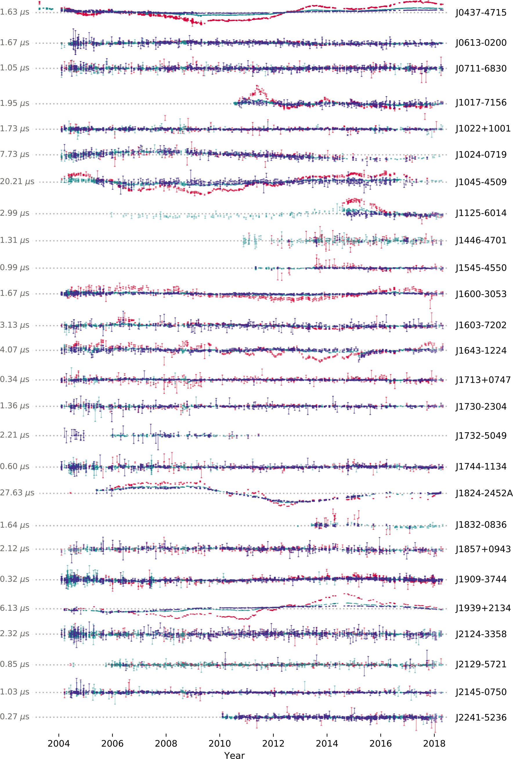
Figure 5. Band-averaged timing residuals for the PPTA DR2 pulsars prior to fitting for DM variations and frequency-independent red noise. The value to the left of the residuals for each pulsar is the weighted rms residual from the model fit. The 10, 20, and 40-cm observing bands are shown in blue, cyan, and red, respectively.

Figure 6. Timing residuals for the PPTA DR2 pulsars as in Figure 5, but with the best-fitting realisation of the DM variations subtracted.
Our data collection contains the pulse arrival times for each pulsar along with our initial timing ephemerides and noise models. We also provide data files used during the pipeline processing, including pulse profiles, standard templates, the flux and polarisation calibration files, and the psrsh scripts. Full details are provided in the README file provided with the data collection.
5. Discussion
5.1. The DR2 data set
The PPTA DR2 data set significantly improves our DR1 data set (Manchester et al. Reference Manchester2013). Data spans are significantly longer with an extra 8 yr of data from 2011 to 2018. For  $\text{PSR\ J}1909{-}3744$
, one of the best timed pulsars, the data span in DR2 is now twice that of DR1. For most pulsars, the data span is about 14 yr, which is greater than the orbital period of Jupiter. This will improve our ability to detect errors in the solar system ephemerides, which are already known to affect PTA data sets (Tiburzi et al. Reference Tiburzi2016; Arzoumanian et al. Reference Arzoumanian2018a).
$\text{PSR\ J}1909{-}3744$
, one of the best timed pulsars, the data span in DR2 is now twice that of DR1. For most pulsars, the data span is about 14 yr, which is greater than the orbital period of Jupiter. This will improve our ability to detect errors in the solar system ephemerides, which are already known to affect PTA data sets (Tiburzi et al. Reference Tiburzi2016; Arzoumanian et al. Reference Arzoumanian2018a).
In contrast to the first data release, DR2 provides ToAs for sub-bands within the bandwidth of each instrument as well as band-averaged ToAs. There are advantages and disadvantages to each type of data set. For instance, the sub-band files for  $\text{PSR\ J}0437{-}4715$
contain 29 316 ToAs. Processing such large numbers of ToAs is computationally expensive (in particular, for Bayesian inference and Monte Carlo simulations), and small variations in the residuals are difficult to identify by eye. In contrast, the sub-banded ToAs enable studies of pulse shape evolution, detailed studies of ISM effects, greater finesse in flagging observations, and a more accurate assessment of the scatter in the residuals. Sub-banded ToAs are especially valuable where the mean pulse profile changes over the band and broadband scintillation is present. Consequently, the choice of whether to use the sub-band ToAs or the band-averaged ToAs depends on the goal of the data processing, on the particular pulsar, and on the computing power available.
$\text{PSR\ J}0437{-}4715$
contain 29 316 ToAs. Processing such large numbers of ToAs is computationally expensive (in particular, for Bayesian inference and Monte Carlo simulations), and small variations in the residuals are difficult to identify by eye. In contrast, the sub-banded ToAs enable studies of pulse shape evolution, detailed studies of ISM effects, greater finesse in flagging observations, and a more accurate assessment of the scatter in the residuals. Sub-banded ToAs are especially valuable where the mean pulse profile changes over the band and broadband scintillation is present. Consequently, the choice of whether to use the sub-band ToAs or the band-averaged ToAs depends on the goal of the data processing, on the particular pulsar, and on the computing power available.
The DR2 arrival times can be used for many purposes, but we caution that the modelling of timing noise and instrumental jumps is preliminary and should be reassessed for any particular application. To aid in this, we have provided initial pulsar ephemerides containing pulsar parameters, instrumental jumps, and noise models. As some of the jumps, pulsar parameters, and noise models are covariant, we have provided initial Bayesian noise parameters. These can be used with an up-to-date version of tempo2.Footnote i
5.2. Known timing events affecting the DR2 pulsars
The following timing events have already been detected in the timing residuals for the DR2 pulsar sample:
-
$\text{PSR\ J}0437{-}4715$
: In 2015 February, a variation in the profile for this pulsar was detected. We will analyse and present details of this event elsewhere.
-
$\text{PSR\ J}1017{-}7156$
: An extreme scattering event (ESE) was reported between MJDs 55600 and 55800 by Coles et al. (Reference Coles2015).
-
$\text{PSR\ J}1024{-}0719$
is thought to be in a long-period binary orbit; see Bassa et al. (Reference Bassa2016) and Kaplan et al. (Reference Kaplan2016).
-
$\text{PSR\ J}1603{-}7202$
: An ESE between MJDs 53740 and 54000 was identified by Coles et al. (Reference Coles2015).
-
$\text{PSR\ J}1643{-}1224$
: Shannon et al. (2016) reported on profile variations starting in Reference Shannon2015 March. This event can easily be seen by eye in Figure 5.
PSR
$\text{J}1713+0747$
: Coles et al. (Reference Coles2015), Desvignes et al. (Reference Desvignes2016), and Lentati et al. (Reference Lentati2016) showed that the line of sight to this pulsar went through an under-dense region of the ISM around 2008 November (MJD 54800). A second similar event at MJD 57500 was reported by Lam et al. (Reference Lam2018). These events are too small to be easily seen in Figure 5PSRs
$\text{J}1022+1002$
,
$\text{J}1730{-}2304$
, and
$\text{J}1824{-}2452$
A are located near the ecliptic plane and show significant excess dispersive delay from the solar wind when close to the Sun on the sky. While observations at these epochs are useful for studying the structure solar wind, care would need to be taken before including them in precision timing studies (Tiburzi et al. Reference Tiburzi2019).


5.3. Continuing the PPTA observations
The primary goal for PTA projects is to detect and study ultra-low-frequency GWs. Bounds of the amplitude of any such GWs are currently dominated by a few of the best timed pulsars (e.g., PSRs  $\text{J}0437{-}4715$
,
$\text{J}0437{-}4715$
,  $\text{J}1909{-}3744$
, and
$\text{J}1909{-}3744$
, and  $\text{J}1713+0747$
) (see, e.g., Shannon et al. Reference Shannon2015). However, any detection of a GW background signal would require strong evidence for a measurement of the ‘Hellings-Downs’ curve that describes the signal correlation between pulsars as a function of their angular separation (Hellings & Downs Reference Hellings and Downs1983; Tiburzi et al. Reference Tiburzi2016). This requires a large sample of pulsars that are timed over long data spans (Siemens et al. Reference Siemens, Ellis, Jenet and Romano2013).
$\text{J}1713+0747$
) (see, e.g., Shannon et al. Reference Shannon2015). However, any detection of a GW background signal would require strong evidence for a measurement of the ‘Hellings-Downs’ curve that describes the signal correlation between pulsars as a function of their angular separation (Hellings & Downs Reference Hellings and Downs1983; Tiburzi et al. Reference Tiburzi2016). This requires a large sample of pulsars that are timed over long data spans (Siemens et al. Reference Siemens, Ellis, Jenet and Romano2013).
However, it is doubtful that pulsars such as PSRs  $\text{J}1939+2134$
or
$\text{J}1939+2134$
or  $\text{J}1824{-}2452$
A, which exhibit significant timing noise, will contribute to the detection of a GW background. We continue to observe such pulsars for the following reasons:
$\text{J}1824{-}2452$
A, which exhibit significant timing noise, will contribute to the detection of a GW background. We continue to observe such pulsars for the following reasons:
The observations are intrinsically interesting, allowing studies of, for example, binary evolution, globular cluster dynamics, and variations in the interstellar medium (ISM). All of these also represent noise sources for precision timing, so their study can help improve timing precision.
PSR J1939+2134, as the first discovered millisecond pulsar (Backer et al. Reference Backer, Kulkarni, Heiles, Davis and Goss1982), provides the longest data spans available for millisecond pulsar timing. It is a very strong pulsar and provides some of the most precise ToAs measured. Although its red noise limits its value for detecting long-period GWs, its short-term precision makes it valuable for detecting events such as GWs from: memory events; cosmic strings; bursts; sinusoidal sources with periods less than a few years; or periastron passages. Since it is also visible to all IPTA telescopes it is valuable for synchronising timing, although care must be taken when the frequencies are different as it shows excess chromatic noise due to scattering in the ISM (Lentati et al. Reference Lentati2016).
The detection of GW burst events (either memory events, burst signatures, or periastron passages) does not necessarily require long data spans that are unaffected by timing noise. For instance, PSR
$\text{J}1939+2134$
provides some of the most precise ToAs measured. If a burst event occurs over relatively short timescales, then such pulsars will be invaluable in detecting and studying the burst. For similar reasons, the pulsar has higher sensitivity to high-frequency (periods less than
$\lesssim$
a few year) continuous-wave GW sources.It is likely that many millisecond pulsars will exhibit timing noise over sufficiently long data spans (Shannon & Cordes Reference Shannon and Cordes2010). Pulsars whose residuals are currently dominated by timing noise allow us to study this potentially sensitivity-limiting noise process. A similar analysis on a large sample of normal pulsars (Lyne et al. Reference Lyne, Hobbs, Kramer, Stairs and Stappers2010) indicated that timing noise can be described as a two-state process with correlated pulse shape changes. If such an effect (or something similar) can be identified for millisecond pulsar timing noise, then such noise may potentially be mitigated (cf., Osłowski et al. 2011).
For many of the DR2 pulsars, DM variations produce the largest timing residual deviations. Most of these can be modelled, and hence removed, using multi-frequency observations. However, remnant variations will remain. A study of ESE events, flux density variations, and DM variations in a large sample of millisecond pulsars will enable optimal mitigation strategies to be developed and tested.


During most of the time period spanned by our DR2 observations, the Parkes telescope was the only southern hemisphere telescope carrying out high-precision pulsar timing observations. The observations of PSRs  $\text{J}0437{-}4715$
,
$\text{J}0437{-}4715$
,  $\text{J}0711{-}6830$
,
$\text{J}0711{-}6830$
,  $\text{J}1017{-}7156$
,
$\text{J}1017{-}7156$
,  $\text{J}1045{-}4509$
,
$\text{J}1045{-}4509$
,  $\text{J}1125{-}6014$
,
$\text{J}1125{-}6014$
,  $\text{J}1446{-}4701$
,
$\text{J}1446{-}4701$
,  $\text{J}1545{-}4550$
,
$\text{J}1545{-}4550$
,  $\text{J}1603{-} 7202$
,
$\text{J}1603{-} 7202$
,  $\text{J}1732{-}5049$
,
$\text{J}1732{-}5049$
,  $\text{J}2124{-}3358$
,
$\text{J}2124{-}3358$
,  $\text{J}2129{-}5721$
, and
$\text{J}2129{-}5721$
, and  $\text{J}2241{-}5236$
are therefore unique to this data set.
$\text{J}2241{-}5236$
are therefore unique to this data set.
Since 2019 February (MJD 58526), the MeerTime project on MeerKAT (Bailes et al. Reference Bailes2016) has been observing Southern pulsars. MeerKAT has a sensitivity five times that of Parkes in the 20-cm observing band. A total of 5 000 h over 5 yr has been allocated to the primary pulsar timing projects, but this time must be distributed between studies of millisecond pulsars, normal pulsars, globular pulsar studies, and relativistic binaries. MeerKAT PTA observations will have 300 to 400 h per year (compared with almost 1 000 h for Parkes). For observational efficiency, pulsars that are ‘jitter dominated’ with MeerKAT (and Parkes) should continue to be observed with Parkes (Shannon et al. Reference Shannon2014). With the UWL receiving system, Parkes now has a wider bandwidth (704 to 4 032 MHz, compared with 856 to 1 712 MHz for current observations with MeerKAT) and established polarimetric calibration methods. We also note also that MeerKAT and Parkes are separated by  $130^\circ$
in longitude, giving extended (or even continuous) time coverage for pulsar observations.
$130^\circ$
in longitude, giving extended (or even continuous) time coverage for pulsar observations.
6. Summary and conclusions
We have presented a new data release (DR2) from the PPTA project, with observations spanning 2004 to 2018. The data were produced using a new processing pipeline intended for high-precision pulsar timing observations.
We expect that DR2 will be used for numerous scientific applications, including the hunt for nanohertz GWs, the study of the size and motions of planets in our solar system, the search for irregularities in terrestrial time standards and to obtain a detailed understanding of the individual millisecond pulsars. We have already started work on detailed modelling of the white and low-frequency timing noise in the data, on bounding GW signals and on improving millisecond pulsar timing model parameters. These results will be presented in future papers.
The data release is stand-alone and publicly available for download and use (https://doi.org/10.25919/5db90a8bdeb59). We anticipate that it will be combined with the IPTA data sets and hence become part of the most sensitive data sets available for PTA research.
Our pipeline is based on input data files that can be loaded and processed using the psrchive software suite, and hence the pipeline can be used for many of the pulsar projects being carried out at Parkes (including P574 and P789; Johnston & Kerr Reference Johnston and Kerr2018; Parthasarathy et al. Reference Parthasarathy2019). It would also work with most data sets from the IPTA telescopes as well as the emerging telescope systems, such as Five-hundred-meter Aperture Spherical Telescope and MeerKAT, and the planned SKA, provided these are based on psrchive-compatible file structures. These high-gain telescopes are likely to carry out relatively short observations of thousands of pulsars (and hundreds of millisecond pulsars). In contrast to the current PPTA sample of pulsars, such data sets cannot be curated carefully by hand and automated pipelines will be necessary. As these telescopes will be the most sensitive available, but also will not have significant overlap in sky coverage, it will become challenging to confirm any results from these new telescopes using a different system. It is therefore important that the processing is carried out in a transparent manner that provides reproducibility and provenance. The pipeline procedures developed for DR2 are a step in this direction.
It would be possible to make incremental improvements to the data set. For example, by combining with IPTA partner data sets, it will likely be possible to determine the fitted jumps to higher precision. Similarly, further investigations with RFI excision methods (Lazarus et al. Reference Lazarus, Karuppusamy, Graikou, Caballero, Champion, Lee, Verbiest and Kramer2016) and wide-band timing methodologies (Pennucci et al. Reference Pennucci, Demorest and Ransom2014) are likely to be beneficial. Significant improvements in the quality or extent of the PPTA DR2 data set will be the subject of future data releases.
We have now transitioned to the UWL receiver system. Instead of carrying out observations first in the 20-cm band and then again with the dual-band receiver, we can now obtain the entire band from 704 to 4 032 MHz in a single observation with higher sensitivity, especially at the high end of the band. This enables us to at least halve the observing time required to achieve similar results to those presented in this paper as well as ensuring that we are less affected by diffractive scintillation. We have therefore been able to increase the number of pulsars being observed by the PPTA. Even with the significantly improved instrumentation now available at the Parkes Observatory, the legacy data sets presented here have enormous value. Most PTA-style projects rely primarily on high-precision timing over long data spans, and therefore these DR2 observations will continue to be analysed as part of future pulsar timing programmes. We have an approximately 1-yr overlap between the old and new systems that will enable the new data to be joined to DR2 with precisely measured timing offsets.
Acknowledgments
We thank the referee, J. Verbiest, for suggestions and comments that improved the manuscript. The Parkes radio telescope is part of the Australia Telescope, which is funded by the Commonwealth Government for operation as a National Facility managed by CSIRO. This paper includes archived data obtained through the Australia Telescope Online Archive and the CSIRO Data Access Portal (http://data.csiro.au). Work at NRL is supported by NASA. M.B., S.O., and R.M.S., acknowledge Australian Research Council grant FL150100148. R.M.S. also acknowledges funding support through Australian Research Council Future Fellowship FT190100155. P.D.L. is supported by Australian Research Council Future Fellowship FT160100112 and Discovery Project DP180103155. Parts of this research were conducted by the Australian Research Council Centre of Excellence for Gravitational Wave Discovery (OzGrav), through project number CE170100004. H.G.W. is supported by the National Natural Science Foundation of China (11573008). J.W. is supported by the Youth Innovation Promotion Association of Chinese Academy of Sciences. This research has made use of NASA’s Astrophysics Data System.
Author contributions
The PPTA project has a large number of team members. The authors (in the initial non-alphabetical section) led specific aspects of the work to develop the data release presented here or carried out a large fraction of the observations. The remaining author list is in alphabetical order and includes individuals who were involved in the project during the time spanned by the observations reported here.
A. Example of a psrsh script
We provide a typical psrsh script that is available in our data collection and corresponds to processing an observation of  $\text{PSR\ J}1603{-}7202$
(the observation file name is t081012_075319.rf). We note that this script has specific directory structures for our computer systems, but the use of a simple Python module specifying such structure means this can easily be modified for other systems. (We also note that here we have updated the details of our file structure to a simpler system; the psrsh scripts in the data collection contain the full paths). A # symbol indicates a comment line. These are automatically generated by the pipeline scripts. The psrsh script is generated by a Python framework and associated metadata and is then run automatically by the PPTA DR2 processing pipeline.
$\text{PSR\ J}1603{-}7202$
(the observation file name is t081012_075319.rf). We note that this script has specific directory structures for our computer systems, but the use of a simple Python module specifying such structure means this can easily be modified for other systems. (We also note that here we have updated the details of our file structure to a simpler system; the psrsh scripts in the data collection contain the full paths). A # symbol indicates a comment line. These are automatically generated by the pipeline scripts. The psrsh script is generated by a Python framework and associated metadata and is then run automatically by the PPTA DR2 processing pipeline.
load /rawData/J1603-7202/t081012_075319.rf
# * Set 1050CM feed parameters.
edit rcvr:basis=lin
edit rcvr:hand=-1
edit rcvr:sa=0.0
edit rcvr:rph=0.0
# * Replace aliased pulsar name with the preferred one.
# * pdfb4.*_1024_[1,2]… chan 2.230 0.188 54751.30 55319.18 081012 100503
# * PDFB4_2bin issue 54751.30 to 55319.18
edit ext:stt_offs=0.000965354880627
# * Apply pdfb4_reset_bug flag to PDFB4 data between MJD 54731 and 54751.30.
zap edge 0.05
cal load /calData/J1603-7202/t081012_075036.cf.dzT
cal
cal frontend
cal load /fluxcalData/pdfb4_10cm_1.avfluxcal
cal flux
edit dm=38.0488
install par /ephemerisData/J1603-7202.par
# Compute full resolution dynamic spectrum.
dynspec /output/t081012_075319.rf.pcm.dynspec
/template/J1603-7202_10cm_ana_PDFB2.std
tscrunch 8
fscrunch 32
unload /output/J1603-7202/t081012_075319.rf.pcm.
dzt8f32
tscrunch 1
fscrunch 1
unload /output/J1603-7202/t081012_075319.rf.pcm.
dzTF
pscrunch
unload /output/J1603-7202/t081012_075319.rf.pcm.
dzTFp
The overall organisation follows a reduction from the original, high-frequency uncalibrated data to final, highly averaged profiles. There are multiple outputs, and care is taken to avoid redundant processing. In brief, this script loads the original data file (the load command) and ensures that the feed parameters are set (edit rcvr:*) so that calibrated data are consistent with the PSR/IEEE convention (van Straten et al. Reference van Straten, Manchester, Johnston and Reynolds2010). Any known issues in the time stored in the header are fixed (edit ext:stt_offs) and then 5% of the band edges are removed (zap). The calibration file is loaded (both the pulsed calibrator prior to the observation and the flux calibration information) and the data file is calibrated (the cal set of commands; note that calling cal without any arguments applies the loaded polarisation calibrator). The DM is set using edit dm and an initial parameter file used to ensure that all files are processed using the same set of parameters for a given pulsar (install par). A dynamic spectrum of the calibrated file is then produced (dynspec), and the output profile averaged to 8 time sub-integrations and 32 frequency channels (tscrunch, fscrunch). An output file with file extension dzt8f32 is produced and then the profile is further averaged in time and frequency (to produce a file with extension dzTF) and then finally a Stokes I profile is output (with extension dzTFp).
B. Example of a rule set used by the pipeline
The following is an example of a set of rules related to manual RFI removal. Some manual RFI removal was necessary. By following these rule sets, it should be possible to reproduce our RFI flagging. -z indicates the removal of a particular channel, while -w a particular sub-integration. The comments written (lines preceded by #) are generated by the pipeline.
# Some bands are relatively clean and we don’t
want to run automatic
# RFI zapping. So just enumerate affected subints
here.
# Format:
# basename_of_observation 1,2,30
@manual
# PSR J0437-4715
w040504_051040.rf -w 12-15
w040815_200745.rf -z 146
w040816_182842.rf -z 146
w040816_190614.rf -z 146
w040816_202134.rf -z 146
w040816_205514.rf -z 146
w040830_184220.rf -z 146
w040831_172241.rf -z 146 -w 19,20
w040831_185715.rf -z 146
w040901_173923.rf -z 146
w040901_185956.rf -z 146
w041023_123208.rf -w 32
w050510_070547.rf -w 6
m2004-06-03-02:56:00.rf 19-24
n2004-08-28-20:19:59.rf -z 0-11 -w 0,3,4,5,14
…
The following is an example indicating which data files are affected by catastrophic RFI and cannot be recovered. The rule @catastrophic_rfi maps to a Python function responsible for treating the tabulated observations:
# Observations so strongly affected by RFI that
every subint/channel
# is affected. E.g., early occurrences of
aircraft-radar interference.
# These data are a total write-off and should not
be processed.
# The directive below applies flag to data.
# NB that these pulsars are specifically those
used in PPTA. It’s
# sensible to separate them since there are so
many observations per pulsar.
@catastrophic_rfi
# PSR J0613-0200
p150831_225744.rf
p150831_230240.rf
# PSR J0711-6830
p151221_113232.rf
…
C. Example of jumps in parameter files
The parameter files in our data release are not suitable for detailed studies of the pulsars themselves. Instead, they provide an initial set of parameters along with a set of ‘jumps’ that correspond to a given observing system, or time range. As an example, we show the relevant ‘jump’ parameters for  $\text{PSR\ J}0711{-}6830$
:
$\text{PSR\ J}0711{-}6830$
:
JUMP -h 20CM_H-OH_CPSR2m -5.0824507989795e-07 1
JUMP -h 20CM_H-OH_CPSR2n 4.1751150972045e-07 1
JUMP -h 20CM_H-OH_PDFB4 5.8676673063388e-07 1
JUMP -h 20CM_H-OH_PDFB1 -1.5895467008059e-06 1
JUMP -h 20CM_MULTI_CPSR2m -1.2285860948976e-06 1
JUMP -h 20CM_MULTI_CPSR2n -1.2852059355821e-06 1
JUMP -g 50CM_CPSR2 1.9184474567463e-06 1
JUMP -g 10CM_WBCORR -1.2985508878209e-07 1
JUMP -h 20CM_MULTI_PDFB1 -1.608849753432e-06 1
JUMP -g 10CM_PDFB1 -6.9361254364538e-07 1
JUMP -g 20CM_PDFB2 -9.0880524215454e-07 1
JUMP -g 10CM_PDFB2 -2.3135497068471e-06 1
JUMP -g 20CM_PDFB3 -1.4283590712073e-06 1
JUMP -g 40CM_PDFB3 -3.6219962470862e-07 1
JUMP -g 40CM_CASPSR -2.5577420710035e-06 1
JUMP -g 20CM_PDFB4 -1.9669236905371e-06 1
JUMP -j 10CM_55319_PDFB4 8.4851151925669e-07 1
JUMP -j 20CM_55319_PDFB4 6.0052124013235e-07 1
JUMP -j 20CM_55319_PDFB3 5.5713865081463e-08 1
JUMP -j 40CM_55319_PDFB3 -2.2188193035067e-06 1
JUMP -cpsr2_50cm 1 -2.36e-06 0
JUMP -cpsr2m_1341 1 -1.72e-06 0
JUMP -cpsr2n_1405 1 -1.8e-06 0
JUMP -dfb3_J0437_55319_56160 1 2.2e-07 0
JUMP -dfb3_J0437_56160_60000 1 4.5e-07 0
JUMP -pdfb1_512_ch 1 -1.22813e-05 0
JUMP -pdfb1_post_2006 1 -1.3e-07 0
JUMP -pdfb1_pre_2006 1 -1.13e-06 0
JUMP -pdfb2_1024_MHz 1 -5.435e-06 0
JUMP -pdfb2_256MHz_1024_ch 1 -1.1395e-05 0
JUMP -pdfb3_1024_MHz 1 1.03e-06 0
JUMP -pdfb3_256MHz_1024ch 1 4.295e-06 0
JUMP -pdfb3_256MHz_2048ch 1 8.32e-06 0
JUMP -pdfb3_64MHz_1024ch 1 1.494e-05 0
JUMP -pdfb3_64MHz_512ch 1 8.9e-06 0
JUMP -pdfb4.*_1024_[1,2]… 1 2.23e-06 0
JUMP -pdfb4_256MHz_1024ch 1 5.05e-06 0
JUMP -pdfb4_55319_56055_cals 1 9.27e-07 0
JUMP -pdfb4_56055_56110_cals 1 3.82e-07 0
JUMP -pdfb4_56110_56160_cals 1 5.41e-07 0
JUMP -wbb_c_config 1 3.8e-07 0
JUMP -caspsr_55500_57575_cals 1 -1.31e-06 0
JUMP -pdfb4_57575_65000_cals 1 1.71e-07 0
JUMP -pdfb4_56160_57575_cals 1 4.25e-07 0
JUMP -caspsr_57575_65000_cals 1 -1.533e-06 0
Table C1. Timing offsets in the PPTA DR2

The final column (a zero or a one) indicates whether the jump has been measured precisely and should be held fixed (a zero) or whether the jump should be fitted for as part of the timing procedure (a one). A complete list of offsets that have been measured and therefore should be held as fixed values in the timing model fitting process are listed in Table C1. Offsets that are allowed to vary in the timing model fit are also listed in Table C1. Note that the values for these jumps are often significantly different between the pulsars.
The jump naming convention reflects the a changes in the type of instrumental offsets experienced over the projects duration. Prior to MJD 55318, the digital filterbanks (PDFB1,PDFB2,PDFB3, PDFB4) and wide-band correlator had instrumental jumps that depended on the specific frequency, and phase bin resolution configuration. This was removed with firmware updates to the system. Post-MJD 55318 timing offsets are related to physical movements of systems or changes in cable lengths in signal paths. We refer the reader to M+13 for discussion of the origin of instrumental offsets.
D. Example of pulse ToAs
The following is part of  $\text{PSR\ J}0711{-}6830$
.tim, the arrival time file corresponding to observations of
$\text{PSR\ J}0711{-}6830$
.tim, the arrival time file corresponding to observations of  $\text{PSR\ J}0711{-}6830$
.
$\text{PSR\ J}0711{-}6830$
.
t180424_104338.rf.pcm.dzTf8p 2908.50000000 58232.46932869677628375 2.83300 pks
- f 1050CM_PDFB4 -g 10CM_PDFB4 -h 10CM_1050CM_PDFB4 -fe 1050CM -be PDFB4
- B 10CM -length 3839.99 -tobs 3839.99 -bw 1024.00 -nchan 1024 -pta PPTA
- tmplt J0711-6830_10cm_ana_PDFB2.std -pdfb4_57575_65000_cals 1 -projid P456
- beconfig pdfb4_1024_1024_1024 -snr 63.15 -gof 0.93 -group PDFB_10CM
- v 10CM_PDFB4 -j 10CM_55319_PDFB4
t180424_104338.rf.pcm.dzTf8p 3036.50000000 58232.46932868819421358 3.30300 pks
- f 1050CM_PDFB4 -g 10CM_PDFB4 -h 10CM_1050CM_PDFB4 -fe 1050CM -be PDFB4
- B 10CM -length 3839.99 -tobs 3839.99 -bw 1024.00 -nchan 1024 -pta PPTA
- tmplt J0711-6830_10cm_ana_PDFB2.std -pdfb4_57575_65000_cals 1 -projid P456
- beconfig pdfb4_1024_1024_1024 -snr 51.96 -gof 0.96 -group PDFB_10CM
- v 10CM_PDFB4 -j 10CM_55319_PDFB4
t180424_104338.rf.pcm.dzTf8p 3164.50000000 58232.46932868052305921 3.69500 pks
- f 1050CM_PDFB4 -g 10CM_PDFB4 -h 10CM_1050CM_PDFB4 -fe 1050CM -be PDFB4
- B 10CM -length 3839.99 -tobs 3839.99 -bw 1024.00 -nchan 1024 -pta PPTA
- tmplt J0711-6830_10cm_ana_PDFB2.std -pdfb4_57575_65000_cals 1 -projid P456
- beconfig pdfb4_1024_1024_1024 -snr 49.66 -gof 0.97 -group PDFB_10CM
- v 10CM_PDFB4 -j 10CM_55319_PDFB4
t180424_104338.rf.pcm.dzTf8p 3292.50000000 58232.46932867376629517 3.43400 pks
- f 1050CM_PDFB4 -g 10CM_PDFB4 -h 10CM_1050CM_PDFB4 -fe 1050CM -be PDFB4
- B 10CM -length 3839.99 -tobs 3839.99 -bw 1024.00 -nchan 1024 -pta PPTA
- tmplt J0711-6830_10cm_ana_PDFB2.std -pdfb4_57575_65000_cals 1 -projid P456
- beconfig pdfb4_1024_1024_1024 -snr 51.84 -gof 1.03 -group PDFB_10CM
- v 10CM_PDFB4 -j 10CM_55319_PDFB4
The file is in TEMPO2 format and details for each observation are given on a single line. The first five columns are required by TEMPO2. These are (1) the filename, (2) the observing frequency corresponding to the ToA determination (MHz), (3) the arrival time (MJD), (4) the ToA uncertainty ( $\mu\text{s}$
), and (5) the site observing code (in all cases this is ‘pks’ corresponding to the Parkes telescope).
$\mu\text{s}$
), and (5) the site observing code (in all cases this is ‘pks’ corresponding to the Parkes telescope).
The remaining columns contain TEMPO2 flags and their values. These are
-f: a flag containing both the frontend receiver (e.g., 1050CM) and the backend instrument (e.g., PDFB4).
-g: similar to ‘-f, but specifying the observing band (e.g., 10CM) instead of the receiver used.
-h: a flag concatenating the receiver, band, and backend instrument.
-fe: the name of the frontend receiver system
-be: the name of the backend instrument
-B: the observing band
-length: the total observation length (seconds)
-tobs:
-bw: the bandwidth of the observation (MHz)
-nchan: the number of frequency channels in the original observation.
-pta: the pulsar timing array recording the data (in our case, all these are set to ‘PPTA’)
-tmplt: the name of the template profile used when forming the arrival times.
-projid: the Parkes observing project (typically P456).
-beconfig: the backend configuration, which is typically the <instrument>_<nbin>_<bw>_<nchan>
-snr: the S/N of the resulting pulse profile
-gof: the goodness of fit during the template matching procedure
-group: a grouping of specific frontend and backend instruments
-v: <band>_<instrument>
-j: fitted jump
Some observations also contain specific flags (such as -pdfb4_57575_65000_cals in the example above) that are used to identify specific groups of data points for flagging or for applying time offsets. Full details of the mapping between delay flags and signal processors, configurations and dates, are available from the ‘ruleSets’ directory in our public data collection.
E. Example and use of a tempo2 select file
TEMPO2 selection files (‘select’ files) are used to enable observations identified via specific instruments or flags to be removed and not included in subsequent analysis.
LOGIC -bad_config = 1 REJECT
LOGIC -caspsr_commissioning = 1 REJECT
LOGIC -corr_prob = 1 REJECT
LOGIC -dfb1_2007_offset = 1 REJECT
LOGIC -nocal = 1 REJECT
LOGIC -notiming = 1 REJECT
LOGIC -pdfb2_commissioning = 1 REJECT
LOGIC -pdfb3_commissioning = 1 REJECT
LOGIC -pdfb3_phase_lock = 1 REJECT
LOGIC -pdfb4_commissioning = 1 REJECT
LOGIC -pdfb4_phase_lock = 1 REJECT
LOGIC -pdfb4_reset_bug = 1 REJECT
LOGIC -pks_clk_prob = 1 REJECT
LOGIC -poor_profile = 1 REJECT
LOGIC -unusual_config = 1 REJECT
LOGIC -varying_profile = 1 REJECT
LOGIC -wbc_phase_lock = 1 REJECT
PROCESS freqpass 600 800
PROCESS freqpass 1200 1500
PROCESS freqpass 2800 3200
LOGIC -length < 300 REJECT
LOGIC -snr < 15 REJECT
PROCESS -fe DRAO REJECT
PROCESS -fe MARS REJECT
PROCESS -fe 13MM REJECT
PROCESS -fe GALILEO REJECT
The first column contains a command. The LOGIC command parses a logical expression to decide on the output. The PROCESS command will carry out a particular processing task given some parameters. For instance:
LOGIC -unusual_config = 1 REJECT
will reject (i.e., not include in further processing) all observations that have been identified with the -unusual_config flag.
LOGIC -snr < 15 REJECT
implies that any observation that has a -snr flag that is smaller than 15 will be rejected. The
PROCESS freqpass 600 800
command will ‘pass’ (i.e., not reject) any observations in which the observing frequency is within the range of 600 to 800 MHz. The selection file can be implemented using a tempo2 command line that includes the -select <filename> command line argument.


