


DISCUSSION POINTS
-
• Renewable hydrogen is a critical need for sustainability regardless of fuel cell markets and transportation applications. Hydrogen has cross-sectoral implications and is particularly effective at addressing limitations across the energy system.
-
• Product development is a long process with research extending well beyond initial materials development, and application requirements may not match the easiest technical pathway. The realities of taking a new technology to scale requires making the most of the existing technologies.
-
• Cooperation and interaction between scientists doing fundamental research and industry device experts are essential for accelerating development and leveraging synergies between long-term and short-term R&D.
Defining the need for renewable hydrogen
Climate change challenges, air quality concerns, and political ramifications of fossil fuel use all are pushing the global society to overhaul the fossil fuel-based energy system which we have been running the planet under since the Industrial Revolution. Recent energy analyses from Lawrence Livermore National Lab (LLNL) estimate that 2% of U.S. energy usage already goes through hydrogen as an intermediate from the energy source to the end use. Reference Pivovar1 Sustainable sources of hydrogen can therefore make large differences in the energy landscape. Hydrogen is one of the most common feedstocks on the planet, though it is not found in its elemental form. Once extracted, it is used for a variety of chemical processes, as a reactant or as a process gas. For example, the largest uses for hydrogen are ammonia production and crude oil refining, including desulfurization of crude oils. Hydrogen is also used in dehydrogenation reactions, synthesis of hydrocarbons such as methanol and cyclohexane, in the glass and electronics industries to protect against oxidation, and as a carrier gas for gas chromatography. Figure 1 shows some of the largest industries and emerging applications that consume hydrogen as a fuel or reactant.

Figure 1. Major energy sources for hydrogen production and major hydrogen uses. Reference Satyapal2
Today, hydrogen is primarily synthesized by steam reforming of natural gas (methane, CH4), with over 90% of hydrogen production in the United States derived from this process. 3 Globally, significant amounts of hydrogen are also made from coal and oil, with only 4% being produced via electrolysis as of 2007 (Fig. 2). As discussed below, there are niche applications where electrolysis is already cost-competitive, and these markets can help drive cost reduction and performance improvements to expand the economic viability of hydrogen produced via electrolysis in broader markets.

Based on the widespread use of hydrogen and the large fraction that is currently produced from fossil fuels, any plan for heavy decarbonization of energy use would need to include pathways for carbon-free hydrogen production, such as from water splitting. In addition to the direct emissions reduction for the existing hydrogen industry, renewable hydrogen can enable cleaner processes in the industry and transportation. For example, steelmaking accounts for 4–7% of the greenhouse gas emissions globally. 5 Leveraging pure hydrogen as a reductant in the process can reduce these emissions over conventional processes and is currently being explored. Also, hydrogen’s flexibility allows increased deployment of carbon-free/renewable power generation by acting as an energy carrying intermediate. Efforts predicting future system wide energy models typically include significant amounts of hydrogen as a key enabling component. 6,7 LLNL “future case” analyses show up to 9% of US energy passing through hydrogen as an intermediate in a high renewables scenario. Reference Pivovar8
Despite the data available for the above scenarios and the large existing hydrogen markets, a common misconception in the scientific community is that the most important application driving the need for cost effective carbon-free hydrogen production is to enable adoption of fuel cell hybrid electric vehicles (FCEVs). While the hydrogen infrastructure is becoming a bottleneck for the FCEV rollout as several car companies led by Toyota and Hyundai are announcing commercial vehicle rollouts, the hydrogen supply market for this application is a small piece of the overall picture and is not very representative as a case study. First, the price points for renewable hydrogen for fueling are not driven by commodity hydrogen pricing but by oil prices and resulting gasoline costs. At current costs for compression, storage, and dispensing, the hydrogen production cost would have to be unrealistically low to compete with today’s gasoline costs. However, the present challenges in making renewable hydrogen cost-competitive with gasoline should not suggest that renewable hydrogen cannot compete on price in other hydrogen markets. Second, even projecting highly aggressive volumes for sale of FCEVs, the hydrogen consumption would be a relatively small part of global demand. At 100 million vehicles, the added hydrogen demand would be approximately 10 million metric tons of hydrogen per year, or 20% of the current global supply. Reference Sarkar and Satyapal9
It should also be noted that hydrogen has a very different pricing for different markets and locations. At a large ammonia plant or oil refinery which might require several hundred tons of hydrogen per day, a large reforming plant is typically co-located due to the constant and predictable need for large quantities of hydrogen, providing very low cost hydrogen due to the economies of scale in building very large process plants. However, if the hydrogen has to be transported from the point of production to the point of use, the economics rapidly change as the delivery distance grows. In addition, similar to other commodity chemicals, pricing for smaller deliveries or higher purity can be substantially higher than bulk materials. A similar point can be made for carbon monoxide or other value-added chemicals derived from waste carbon dioxide. While simple molecules like methanol, ethylene, and carbon monoxide are low in cost at very high production volumes, purchasing smaller quantity batches or higher purity increases the cost substantially. Distributed systems for generating these compounds on site can therefore enter the market at higher price points and effectively compete as the technology is being scaled.
Examples of electrolyzer markets at various hydrogen scales are shown in Fig. 3 (Source: Proton OnSite). In addition to capital cost, considerations such as OSHA requirements and inventory limitations, security of supply, operating cost, safety, purity, and other factors contribute to customer decisions on hydrogen supply solutions. These initial markets have established the reliability of the cell stacks and scalability of the design, paving the way for increasingly larger markets.

Figure 3. Commercial electrolyzer systems and markets where they compete with delivered hydrogen from steam methane reforming. 1 kW corresponds to roughly 300–400 g H2/day.
As these systems have been commercialized, the cost of electrolysis has decreased substantially, despite little changes in the basic technology in terms of materials of construction and manufacturing methods (Fig. 4). This progression demonstrates several points: (i) the high relative cost of any technology at a small scale or early product introduction, (ii) the improvements based on experience and scale alone, with additional potential for improvements through advanced materials and automated manufacturing, and (iii) the credibility for a pathway to economical renewable hydrogen at scale.

Figure 4. Normalized cost based on input power level as a function of the commercial system size. Source: Proton OnSite.
Realities of scale and product development
To address the goal of deep decarbonization by 2050, near term technologies will need to be deployed in high volumes. Product development from lab proof of concept to commercial volumes at scale is a very long process. Leveraging and maximizing the effectiveness of today’s technologies provide the base for newer technologies to build on and also provide stepping stones to accelerate research and development. The industry is not going to be able to turn on a switch in 2050 to install a perfectly developed technology at gigawatts to terawatts of capacity. The groundwork has to be built now.
To illustrate this principle, a deployment model was developed using the assumptions below. Existing technologies were purposely biased on the conservative side while developing technologies were purposely biased to the aggressive side to demonstrate the principle even under the most favorable conditions for development. In addition to the technologies presented, it should be noted that there are also older low temperature electrolysis systems which use concentrated potassium hydroxide (KOH) in water as the electrolyte rather than a solid electrolyte such as an ion exchange membrane. KOH systems have been deployed at multi-megawatt scale and are still used for certain applications. Disadvantages include the need to operate at balanced pressure (requiring either mechanical compression of the generated hydrogen, or generation of oxygen at elevated pressure, which presents additional safety risk), corrosive electrolyte as the circulating fluid, and lower operating current densities. Membrane-based systems such as those leveraging proton exchange membranes (PEM) as the solid state electrolyte can generate electrochemically compressed hydrogen with minimal additional overpotential while maintaining the oxygen loop at ambient pressure and can operate at higher current densities, offsetting the higher material costs. Commercial PEM electrolyzers typically operate at 1.5–2 A/cm2, while KOH systems operate below 0.5 A/cm2. At similar system scales, PEM systems compete on price with KOH systems. De-ionized water is also used as the circulating fluid in the membrane systems because the membrane serves as the supporting electrolyte, minimizing chemical hazards. While existing liquid KOH technology could also contribute to hydrogen production at a large scale and will likely continue to serve some large-scale industrial markets for some time, PEM systems are similar in cost at the same output and have a wider dynamic range for following renewable loads. For simplicity, KOH systems are therefore not included in the analysis but would only decrease the impact of longer term technologies.
Assumption 1: PEM systems can reach 100 MW scale installations within 10 years
PEM electrolysis is already at a 2 MW scale. Electrolysis systems have previously been scaled by factors of 50 in two product generations, within similar 10-year time frames, providing credibility to this projection. For example, Proton’s 40 kW system was released in 2004, while the 1 and 2 MW systems were released in 2014. In addition, existing platinum and iridium production can support a gigawatt level annual production, even at the high catalyst loadings currently used. Figure 5 below shows the relative hydrogen output across several product lines, on a log scale. A 100 MW scale would represent 40,000 kg/day. Also noted on the graph is the capacity of a 100 cm2 electrode operating at 10 mA/cm2 (circled in red) for the perspective on how far nascent technologies have to go to reach these output levels (close to 7 orders of magnitude).

Figure 5. PEM electrolysis scale development.
Assumption 2: low temperature membrane systems become a mix of PEM and AEM technology, with AEM lagging by about 8 years
Anion exchange membrane (AEM) electrolysis is very similar to PEM but is currently much less mature due to the lack of membrane options. The membrane is still used as the electrolyte but conducts hydroxide ions rather than protons, creating a higher local pH and allowing a broader range of catalyst and cell materials. AEM technology thus has the same advantages of the liquid KOH systems, while also leveraging membrane advantages: enabling lower cost materials of construction but still allowing noncorrosive electrolyte and differential pressure operation. This growth assumption relies on the development of stable anion exchange membranes and ionomers, but existing stack platforms and balance of plant for PEM systems can be heavily leveraged once the materials mature, allowing a very rapid scale up. The takeover rate of PEM by AEM may be optimistic, but the overall growth of membrane-based systems (PEM and AEM combined) is conservative.
Assumption 3: high temperature solid oxide electrolysis (SOEC) matches the growth curve for AEM technology
Solid oxide electrolysis cells (SOEC) are based on solid oxide fuel cell technology, in which an oxide or ceramic material is used as the electrolyte. These systems operate at much higher temperatures (typically 600–800 °C), which enable a broader range of fuel flexibility for the fuel cell and higher efficiency for both the fuel cell and electrolysis operation due to low activation polarization at the catalyst. While the solid oxide electrolysis technology also has some ability to leverage existing commercial fuel cell systems with similar materials, there are differences between the fuel cell and electrolysis requirements, which drive modifications to the cell stack. The balance of plant also requires significant differences. There are a few, if any, commercial SOEC systems to date, and the solid oxide electrolyzer technology will not have the balance of plant piping and instrumentation layouts and electrical and controls definition that already exists for low temperature membrane-based electrolyzers at the MW scale and above. Matching low temperature growth is therefore a highly optimistic assumption.
Assumption 4: photoelectrochemical (PEC) hydrogen production reaches 100 kW scale in 10 years and 5 MW scale in 20 years
Direct photoelectrochemical hydrogen production involves combining the function of a traditional photovoltaic solar cell with an electrolysis cell, such that the electrode both absorbs light and electrochemically splits water. The electrode requires a large enough energy band gap to provide sufficient electrical potential for water splitting, and the surface structure has to both absorb light and be catalytic for hydrogen and oxygen evolution. Due to typical solar fluxes and the potential required to split water, these devices operate at a low current density, on the order of 10 mA/cm2. For perspective, a 100 kW system at this current density would require roughly 1000 m2 of electrode area. Today, most prototype cells are 100 cm2 or smaller: 5 orders of magnitude different, and no balance of plant has been developed at any scale for collection and purification of hydrogen. This projection is therefore highly optimistic and represents aggressive growth, as acknowledged by several researchers in the field.
Assumption 5: solar thermochemical hydrogen (STCH) production lags PEC maturity by two years
Solar thermochemical hydrogen production (STCH) uses concentrated solar energy to heat a receiver, such as concentration via heliostat mirrors, to thermally split water at high temperature (∼2000 °C). Nuclear energy waste heat can also be used to provide the heat source, and either pathway results in hydrogen generation with near zero greenhouse gas emissions. While this growth assumption is fairly arbitrary, there are many aspects of STCH that are still relatively immature, with little agreement across the field on system configuration, standard tests, operating conditions, etc. Some prototyping is being developed, but no commercialization pathways have been defined, and experts in the field have validated this assumption as highly optimistic.
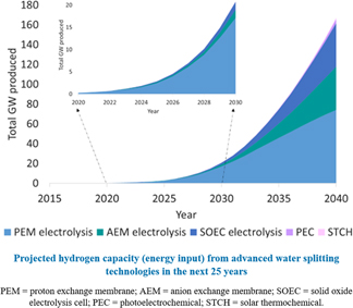
The cumulative capacity realized by these assumptions is shown in Fig. 6. Through 2030, even with very optimistic and aggressive growth assumptions on all other technologies, the existing commercial electrolysis technology is the only one that makes any significant impact. Even by 2040, low temperature electrolysis represents close to three-quarters of the total water splitting capacity.

Figure 6. Projections for hydrogen capacity based on maturity and growth assumptions above.
This conclusion is not designed to imply that other advanced technologies should not be part of a complete research portfolio but that investment in long term research that seems to provide a breakthrough to a key obstacle should not be at the complete expense of nearer term technologies that can still be significantly improved and can make larger impact sooner. In addition, technology is a constantly moving target, where game-changing developments can alter the goals and requirements. As an example, the cost reductions in wind and solar installations reduce the electricity cost to the point that electrochemical devices can compete on a lifecycle cost with hydrogen from steam methane reforming, which may not have been true 10 or even 5 years ago.
Technology and manufacturing readiness
The reasons that product development and commercialization takes so long are multi-faceted. First, there is significant understanding needed to translate an idealized system in the lab which may be useful for determining the inherent performance of materials to fabricating components that can be used in a device. For example, the rotating disk electrode (RDE), a common method for determining catalyst activity, is operated in liquid electrolyte, with forced convection, and catalyst loadings of micrograms/cm2. The catalyst is well distributed and the surface has easy access to free ions in the solution. However, the current densities are very low, typically 10’s of mA/cm2 or less, while commercial electrolyzers operate at current densities two orders of magnitude higher. The catalyst layer in a working device is also much more complex, containing binders and ionomers, forming a 3-dimensional electrode on a porous surface with tortuous flow paths (Fig. 7). This electrode is much more difficult to characterize, including understanding of ion transport at the interfaces, variation in the structure as a function of deposition parameters, and degradation over long operating times.

Figure 7. Magnified schematic of RDE (a) versus actual electrode surface (b).
There is a significant science in optimizing these architectures for cost and performance. In addition, there are silos between basic and applied researchers, meaning that they often work in isolation from each other, with little cross-disciplinary communication. For example, there has been an increased focus in academia on catalyst discovery for oxygen evolution in the basic media, since non-noble metal catalysts are more likely to be stable at a high pH. However, this work often ignores the long history of liquid KOH electrolyzer development, where nickel-based catalysts have already shown high activity for many years. At the same time, most of the academic studies are performed in liquid electrolyte, which is not always a good predictor of performance in solid electrolyte systems. Comparing a new catalyst in alkaline solution to a catalyst that performs well in a polymer electrolyte system is comparing apples and oranges. Finally, low overpotential is not sufficient for a practical device, if the catalyst cannot be made in a high surface area format. Catalysts that perform well in RDE but have surface areas of 0.1 m2/g cannot be fabricated in sufficiently high loadings for practical current densities.
Scale up efforts also can result in unexpected behavior and interactions, such as differences in a catalyst morphology or composition due to less uniform thermal gradients at a larger scale. Once the technology is proven in the lab, there is still a long development effort to understand manufacturability and process variables. Many processes for catalyst synthesis depend on the local environment such as concentration and temperature to achieve desired morphologies, stoichiometric selectivity, and particle size. Scaling up reactors can result in larger thermal and concentration gradients that change the output. Similarly, translating hand fabrication of a 5 cm2 electrode developed by a university lab to a process that can coat 500 cm2 areas and larger in an industrial setting requires significant understanding of the parameters and close collaboration between the initial research team and the process team.
Finally, translating a working prototype cell to commercial production is not trivial. Significant engineering is required to develop a system around an electrochemical cell or stack. Flow calculations, thermal management, ventilation, hazard analysis, and control schemes have to be developed to ensure safe operation under a defined range of conditions. In addition, packaging the components into a compact but service-accessible solution that is compliant with relevant codes and standards requires time and investment. Figure 8 below shows examples of a packaged electrolyzer system and a skid-mounted system that might be installed in a plant (top), in comparison to a breadboard test system and an electrochemical cell prototype (bottom). The latter may be able to meet all of the performance targets for the electrode materials but is still far from a commercially viable solution.

Figure 8. Examples of products versus functional prototypes.
Typically, once the research is finalized for the first generation technology, it takes another 10 years to begin market penetration. Reference Stolten10 Fuel cell hybrid electric vehicles (FCEVs) are a relevant example. Automotive developers were interested in fuel cell vehicles in the 1990’s, based on the technology demonstrated in space applications such as the Space Shuttle. Early prototype vehicles from several manufacturers were on the roads by 2001–2005, Reference Nied11,Reference Kurtz, Sprik, Ainscough and Saur12 which already had to pass certain safety standards and were based on vehicle models that had already been basically developed. For example, Proton OnSite had several Toyota prototype FCEVs based on the Highlander model from 2010 to 2016 for demonstration and testing onsite. Commercial vehicles were not released until 2014–2016 (Hyundai, Toyota, and Honda to date), a decade after the start of limited consumer testing and two decades after the beginning of vehicle development based on a known technology used in outerspace. The basic technology had to be reconfigured to meet the specific cost and performance requirements of automotive applications.
Electrolysis status and near term outlook
While electrolysis is an established commercial technology, much of the product development has focused on scale and assembly, with less focus on specific material and process development optimized for electrolysis. Reference Danilovic, Ayers, Capuano, Renner, Wiles and Pertoso13 The companies and component suppliers in this technology area are also primarily smaller, with limited resources, which extend commercialization timelines even further. Electrolysis, therefore, lags far behind fuel cells in material optimization, though lab and subscale experiments have shown an enormous potential for cost and performance improvements. Electrolysis can also leverage learnings from both fuel cells and solar fuel research to guide the design of materials and advanced manufacturing processes. 14
It is important to note that electrolyzers were initially developed for oxygen generation in closed environments, such as manned space missions and submarines. Proton OnSite’s founders came from Hamilton Sundstrand (now United Technologies Aerospace Systems), one of the suppliers of these oxygen generators. This design legacy and associated requirements drove the initial product characteristics. Due to the critical application being served, cost and efficiency were not primary considerations; reliability including resilience to shock and vibration military specifications was the overriding factor. For commercial applications, while long lifetimes are still important, the requirements are not as stringent, and at least in some cases, the required pressure is lower. While one opportunity is in reduction of platinum group metal catalysts, which are currently at very high loadings compared to fuel cells, there are many other areas for cost reduction; the catalyst currently represents less than 10% of the total system cost even at a megawatt scale. This reality is partly because the manufacturing methods are used at low production volumes, which both drive the higher catalyst loadings and are labor and cost intensive themselves. Other areas for cost reduction and performance improvement include membrane development, coatings for oxidative corrosion protection, porous transport layers, and advanced manufacturing methods.
Many of these areas are also considerations for solar fuel research and direct photoelectrochemical water splitting. Alternative catalysts and benchmarking methods for photoelectrochemical systems can be directly applied to “dark” water splitting. Understanding of hydrogen permeation in membranes and behavior under fully flooded conditions are also critical parameters for photoelectrochemical systems. While the conductivity requirements for electrolysis are higher due to the higher current densities, understanding the structure -property relationships that control hydrogen permeation and mechanical strength when fully hydrated can accelerate the electrolyzer membrane development. Similarly, while support structures for electrolyzers do not need the photoactive component required for PEC, designing conductive, three-dimensional structures that are stable at high potentials, particularly in acids, is a challenge common to both devices. Characterization methods to understand the impact of synthesis on the structure as well as in situ methods to determine and mitigate degradation mechanisms are also highly valuable.
At the same time, applied research at the industrial level can inform the basic research. Understanding the actual cost structure and both device and system level limitations help to prevent “solving the wrong problem”. Designing materials which miss key elements of current operational characteristics do not advance the field, unless a simultaneous change in operating parameters can be coordinated. The latter option also requires a close collaboration with the industry and understanding of what changes may be simple versus what changes are much more complex. Returning to the catalyst example, a key advantage of membrane-based systems is the ability to use deionized water as a circulating fluid rather than a strong acid or base. Only testing catalysts in liquid electrolyte with no understanding of how the material performs with solid electrolyte does not drive progress. Also, designing catalysts for a basic solution where there are no stable ionomers and membranes, without solving that problem, does not provide device manufacturers a viable product pathway. Understanding of the context of existing technology can also drive subtle changes in the research direction even at the materials level that can increase the end value of the work. For example, understanding that catalyst loadings higher than a few milligrams/cm2 are detrimental for device performance might drive focus on higher surface area materials earlier.
In summary, the road from technology to product and large scale is long and circuitous. There are scientific and engineering challenges in complex mixtures and multicomponent devices, and idealized systems can only inform part of the issues. Understanding both fundamental and applied perspectives accelerates the technical progress because long term research can be leveraged into short term improvements, while the existing technology provides perspective, stepping stones, and infrastructure for the new technology. Collaborations and synergies between fundamental and applied researchers, and more specifically between academics, national labs, and industry, need to be cultivated from early on in the material discovery process, to guide eventual integration. In addition, better mutual knowledge of the underlying fundamental challenges in existing technologies can result in large breakthroughs through fundamental research. Figure 9 below demonstrates the feedback loop between technology and fundamental research and how understanding of the parameters in the top row can inform the fundamental direction, while the same research can create information that can be leveraged ahead of the end goal.

Figure 9. Schematic representation of how fundamental research directed toward an end goal can be both informed by existing technology and make advancements to nearer-term technologies related to the end goal.
The center row represents basic research elements driving toward a long-term end goal, such as direct photoelectrochemical water splitting. The outer rows represent related technologies of relevance to the industry on a shorter time scale, such as electrolysis. At the top, background knowledge from applied researchers can inform the critical needs for fundamental research as well as point out considerations that can change the results of material testing. At the same time, the capabilities being developed in pursuit of a long term technology can be leveraged earlier for nearer term impact in related technologies, as shown at the bottom. This feedback loop thus benefits both fundamental and applied researchers and helps to accelerate development and shorten the timeline from materials discovery to commercial application. These types of interactions are increasingly important to address global challenges such as energy storage and sustainable manufacturing processes.
Within the U.S., there are many mechanisms for supporting these collaborations, for researchers on both sides of the basic-applied spectrum who are willing to work on pursuing them. They often work best when the university has a unique measurement capability, material knowledge, or synthesis capability, while the industrial company can perform integration of components, design appropriate test cells, provide guidance on and carry out realistic conditions, and perform process development, as examples. Some agencies are highly supportive of multipartner projects that incorporate a mixture of fundamental understandings and practical applications. For example, several divisions of the Department of Energy within the Office of Energy Efficiency and Renewable Energy fund university-industry-government lab projects. ARPA-E (Advanced Research Projects Agency—Energy) also funds a variety of teams, from university-led projects with industrial partners to industrially-led projects with government labs and universities. Similarly, Small Business Innovation Research and Small Business Technology Transfer (STTR) grants across all the agencies allow subcontract agreements with research institutions, and STTRs require them. From the fundamental side, the National Science Foundation has a GOALI (Grant Opportunities for Academic Liaison with Industry) program to promote university-industry partnerships. Including industrial researchers on the scientific advisory boards for research consortia is another way to inject applied perspective and seed follow up opportunities. Internationally, it can be more difficult to form formal partnerships due to the preference for each government to fund research in their own country and few programs are sufficiently aligned to allow for synchronous funding for each partner. Still, seeding small efforts to test materials or co-develop protocols can result in valuable cross-pollination and lead to prototyping through procurement contracts or by other means. Proton has successfully navigated all of these pathways and there are undoubtedly others that are possible.
Acknowledgments
The author gratefully acknowledges Dr. Bryan Pivovar for valuable discussions. The author also acknowledges ARPA-E grant DE-AR0000688 for MRS conference travel at which the original talk was presented.


