


Introduction
Many modern alloys consist of at least two different phases, such as ferrite and cementite in steel, or a layered architecture, such as in TiAl. Their combination in an ordered microstructure results in outstanding mechanical properties. While the mechanical characterization of the system can be easily done at the macroscale, the contribution of the individual phases is hard to determine. For this purpose, microscale setups were developed to measure their tensile,[Reference Kiener, Grosinger, Dehm and Pippan1] compressive,[Reference Uchic and Dimiduk2] or fracture behavior.[Reference Matoy, Schönherr, Detzel, Schöberl, Pippan, Motz and Dehm3,Reference Halford, Rudinal, Takashima and Higo4] However, there are only limited possibilities to characterize the fatigue behavior at the small scale.[Reference Lavenstein and El-Awady5–Reference Alsem, Pierron, Stach, Muhlstein and Ritchie7]
Reliable cyclic methods are available for thin film testing[Reference Merle and Göken8–Reference Putz, Völker, Semprimoschnig and Cordill10] or for custom MEMS (micro-electro-mechanical systems),[Reference Sadeghi-Tohidi and Pierron11] but the knowledge obtained from these specific objects cannot be extrapolated to any 3D structure. Small-scale mechanical testing on other objects typically relies on nanoindentation approaches. Classical pyramidal geometries are poorly suited for accessing the local cyclic behavior[Reference Li and Bhushan12] due to the complex stress state introduced in the sample. Methods with defined stress states should be preferred, such as micropillar compression tests[Reference Schamel, Wheeler, Niederberger, Michler, Sologubenko and Spolenak13,Reference Schwiedrzik, Raghavan, Bürki, LeNader, Wolfram, Michler and Zysset14] and microcantilever bending.[Reference Massl, Thomma, Keckes and Pippan15,Reference Iqbal, Ast, Göken and Durst16] However, there are only few implementations reported and most of the time they are limited to low-cycle fatigue (LCF) testing.[Reference Wimmer, Heinz, Detzel, Robl, Nellessen, Kirchlechner and Dehm17–Reference Eisenhut, Schaefer, Gruenewald, Weiter, Marx and Motz19] Merle et al.,[Reference Merle and Höppel20] as well as Lavenstein et al.,[Reference Lavenstein, Crawford, Sim, Shade, Woodward and El-Awady21] pioneered a new approach to extend small-scale testing to the high-cycle fatigue (HCF) range based on the use of the continuous stiffness measurement (CSM) method.[Reference Merle, Maier-Kiener and Pharr22] The CSM is widely used in nanoindentation systems for monitoring the variation of the hardness and Young's modulus during indentation.[Reference Oliver and Pethica23] Independently from each other, Merle and Höppel[Reference Merle and Höppel20] and Lavenstein et al.[Reference Lavenstein, Crawford, Sim, Shade, Woodward and El-Awady21] pioneered its use as a fast actuation technique for cyclically loading focused ion beam (FIB)-structured samples. Mohanty et al.[Reference Mohanty, Schwiedrzik, Polyakov, Petho, Breguet and Michler24] further extended the testing range by introducing a piezo-based actuator.
Experimental
Ultrafine-grained copper was chosen for the experiments, as its mean grain size of 157 nm is less than a tenth the size of the intended microcantilevers; hence, sampling effects are suppressed. The sample was produced by severe plastic deformation of pure copper (99.99 at.-%) in eight cycles of equal channel angular pressing (ECAP) using the Bc route. The production was done by the group of Prof. Wagner at TU Chemnitz (Chemnitz, Germany). The sample was subsequently ground and electropolished. Microcantilevers were cut out using a Helios Nanolab 600i from FEI (Hilsboro, OR, USA). Gallium currents between 21 nA and 790 pA were used to fabricate cantilevers with an aspect ratio of 25:5:5 μm (L:W:T), similar to.[Reference Ast, Przybilla, Maier, Durst and Göken25]
The microcantilevers were deflected in a G200 Nanoindenter (KLA, Milpitas, CA, USA) with a 20 μm long wedge indenter (Synton MDP, Nidau, Switzerland). The cyclic micropillar method of Merle and Höppel[Reference Merle and Höppel20] was adapted to the testing of bending beams in fatigue. The engineering stress σ and strain ε at the surface of the beam (see Fig. 1) are thereby calculated from the load P and displacement h recorded during the test using the classical elastic bending theory.[Reference Matoy, Schönherr, Detzel, Schöberl, Pippan, Motz and Dehm3] In a second step, the fatigue-specific parameters stress range Δσ max and strain range Δε at the surface of the beam are calculated from the cyclic load ΔP and cyclic displacement Δh:
 $${\rm \Delta }\sigma _{{\rm max}} = \displaystyle{{6{P}L} \over {T\,W^2}}$$
 $${\rm \Delta }\varepsilon = \displaystyle{{3\,{W}\,{\Delta h}} \over {2\,L^2}}$$
where T is the thickness, W is the width, and L is the span length between the contact point of the indenter and the root of the cantilever. Strictly speaking, the strain formula is only correct for elastic bending. It holds true as an approximation as long as only little plasticity has been accumulated.
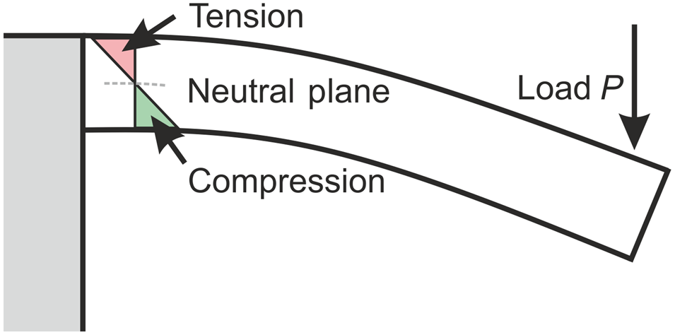
Figure 1. Schematics of the stress distribution inside a microcantilever under bending.
The test method consists of four steps: (i) tip approach to the surface, during which the spring constant calibration of the instrument is refined. (ii) Pre-loading of the cantilever to a stress of σ pre, which is subsequently held constant throughout the test. This pre-compression is necessary to avoid a loss of contact between the tip and the beam during the oscillations. (iii) Ramp-up of the 40 Hz CSM oscillation up to a constant harmonic load ΔP, which is calculated from the user-defined Δσ. (iv) Cyclic testing until failure of the samples, or interruption after 3 ×10⁶ cycles, whichever occurs first. Failure is defined as a 20% decrease of the contact stiffness compared to its initial value. To correct displacement and stiffness effects by the penetration of the indenter into the surface, reference calibrations were made as shown in the Supplementary Material.
The top surface of the cantilevers remains in pure tension during cyclic testing, while a stress gradient reaching from tension to compression develops throughout their thickness, see Fig. 1. The extension of the plastic zone is limited to dimensions even smaller than the diameter of the cantilevers due to the presence of a neutral plane.
The presented investigations are based on approximately 30 cyclic cantilever tests. The observed behavior can be divided between three categories corresponding to low, medium, and high stress amplitudes. For comparison purposes, three cantilevers were chosen, which failed after approximately 1.8 × 10⁶, 5.8 × 10⁵, and 1.6 × 10⁵ cycles.
Results and discussion
Monotonic testing
The quasi-static deformation behavior of the cantilevers was investigated prior to cyclic testing. Figure 2 shows the engineering stress versus the engineering strain, which is calculated by Eq. (2). The yield strength is approximatively 850 MPa, and the cantilever can accumulate more than 6% deformation before failing. The low strain-hardening trend is consistent with the literature on ECAP copper.[Reference Herbert, Oliver and Pharr26,Reference Volkert and Lilleodden27] The postmortem micrographs [Fig. 2(c)] show that the deformation is localized at the root of the cantilever, as the highest stresses are present there [see Eq. (1)]. However, the microstructure remains largely unaltered, without either grain growth or the formation of shear bands.

Figure 2. Monotonic microbeam bending: (a) stress–strain curve. (b,c) Electron micrographs of the specimen prior to and post testing.
Morphology after cyclic testing
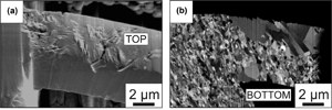
The fatigue specimens were imaged prior to cyclic testing and after the end of the test, i.e. when their stiffness had decreased by 20%. Postmortem images corresponding to three different deformation behaviors are shown in Fig. 3. The cantilever tested with the lowest stress range [Fig. 3(a)] reveals large areas of grain coarsening at the top and the bottom of the microantilever. The cantilever tested at medium stress range [Figs. 3(c) and 3(d)] shows less grain coarsening in the cross-section and extrusions on both the upper and lower sides of the cantilever. The cantilever tested at the highest stress range is characterized by deep extrusions on its surface and very little grain coarsening in the cross-section, see [Figs. 3(e) and 3(f)]. It can be seen that the extrusions on the upper, tensile side of the cantilever coalesced and started to form a micro-crack. This corresponds to the first stage in crack growth, which would ultimately lead to the initiation of a full crack. In contrast, it seems that at lower stress amplitudes, the stresses acting upon dislocations are not sufficient for their transmission through grain boundaries, so grain coarsening needs to take place before persistent slip bands and extrusions can be formed. Such extrusions are seen when the mean grain size reaches a threshold.[Reference Kraft, Schwaiger and Wellner28,Reference Cordill, Glushko, Kleinbichler, Putz, Többens and Kirchlechner29] Grain coarsening is therefore the limiting stage that dominates the lifetime of the samples at medium and low stress amplitude.

Figure 3. Electron micrographs of three representative microcantilevers after testing with different stress ranges Δσ in (a, c, e) inclined view and (b, d, f) cross-section.
Note that for most tested stress amplitudes, grain coarsening and extrusion formation are observed on both top and bottom surfaces of the cantilever. This is because their formation depends on the availability of mobile dislocations, which can be found in either of these highly stressed regions. The presence of extrusions leads to the formation of micro-cracks only at the upper surface, though, because the compressive stress found at the bottom opposes crack opening.[Reference Cottrell, Hull and Mott30,Reference Paris31]
Evolution of cyclic parameters
The cyclic parameters, calculated using Eqs. (1) and (2), were monitored throughout the tests and provide useful information on the fatigue mechanisms. The cyclic stress data confirmed the accuracy of the stress control by the nanoindenter: after the initial ramp-up, the stress range Δσ remained constant throughout the tests. For each test, the evolution of the strain range data Δε hints at three successive stages, see [Fig. 4(a)]. At the beginning of testing, Δε decreases smoothly due to cyclic hardening. This region is followed by a second stage after a minimum in strain range. There, the cyclic hardening behavior of the material is changed into cyclic softening — as visible from the smooth increase of Δε. In the last stage, the strain range increases faster due to accelerated failure. Keeping the logarithmic scale in mind, the cyclic softening stage clearly dominates the lifetime of the cantilevers. These three successive stages are observed for all tested stress ranges Δσ, their main difference being the offset between the Δε curves.

Figure 4. (a) Evolution of the strain amplitude Δε/2 for microcantilevers tested at different stress amplitudes, corresponding to R ratios of 0.029–0.061. (b) S–N curves. The failure criterion was defined as a strain range increase of 20%. The results are compared to previous micropillar compression–compression fatigue tests on the same material.[Reference Merle and Höppel20]
S–N curves were obtained by considering the previously introduced failure criterion (20% increase of Δε). In [Fig. 4(b)], the new results are compared to a previous investigation on the same material by Merle and Höppel[Reference Merle and Höppel20] using cyclic micropillar compression. The slopes of both curves yield a similar fatigue strength exponent of approximately −0.1. However, the microcantilever data show higher scatter and longer fatigue lives. The latter can be accounted for by different R ratios during testing as well as different definitions of the failure criterion. The reasons for the higher scatter will be discussed later.
Microstructural evolution
The cyclic hardening observed at the beginning of the tests [Fig. 4(a)] corresponds to dislocation multiplication.[Reference Vinogradov, Kaneko, Kitagawa, Hashimoto, Stolyarov and Valiev32] The subsequent cyclic softening stage corresponds to microstructural coarsening of the top and bottom regions of the cantilever. On the postmortem cross-sections shown in Fig. 3, it can be seen that some grains grew in size by an order of magnitude. This is consistent with previous observations on ultrafine-grained materials.[Reference Kraft, Schwaiger and Wellner28,Reference Glushko and Dehm33,Reference Sim, Lee, Lee and Vlassak34] Once a saturation size is reached, dislocations are free to glide on such large distances that strain coarsening is replaced by the formation of slip bands and surface extrusions.
In the last stage of cyclic testing, the extrusions grow to small cracks, which lead to a strong reduction in the beam cross-section. However, the transition from the extrusion formation to a failure by pure crack growth in crack mode I was not observed, as the experiments were stopped before this happened, due to the failure criterion on stiffness being reached. The cyclic behavior and the grain coarsening mechanism observed in this study are consistent with previous fatigue tests on high-purity ECAP copper, either on the macroscale[Reference Höppel, Kautz, Xu, Murashkin, Langdon, Valiev and Mughrabi35,Reference Mughrabi, Höppel and Kautz36] or on the microscale by cyclic pillar compression,[Reference Merle and Höppel20] freestanding thin films,[Reference Merle and Göken8] or nanoindentation on bulk samples.[Reference Cordill, Lund, Parker, Leighton, Nair, Farkas, Moody and Gerberich37]
Reliability of the dynamic microcantilever method
The evidenced cyclic behavior is consistent with literature data on high-purity ECAP copper. However, unlike in bulk data, the microcantilever experiments were performed at positive R ratios, which brings along cyclic creep effects.[Reference Eckert, Laird and Bassani38] This, in theory, should shorten the lifetime of the samples, as the fatigue damage is increased by creep. However, our microscale tests should hardly be affected because they only capture the early stages of crack formation. Besides, the fatigue life of high-purity metals — such as investigated for the present study — is known to be dominated by the crack initiation stage.[Reference Paris31] Therefore, the failure criterion based on a stiffness drop by 20% seems to be a reasonable failure criterion at least for high-purity metals.
In comparison to cyclic micropillar testing,[Reference Merle and Höppel20] the cantilever experiments exhibit a larger scattering in S–N data. This is a consequence of the testing geometry. Only a limited volume close to the surface is subjected to the highest tensile stresses during bending, see Fig. 1. Therefore, the measured cyclic behavior depends on a small number of grains and their respective orientations. The cyclic micropillar tests are more reproducible because of the larger sampled volume.
Microbeams under bending are also characterized by a large stress gradient, which leads to the piling-up of an unusually large density of dislocations at the neutral axis. The back stress of the pile-up slows down the crack propagation.[Reference Sadeghi-Tohidi and Pierron11,Reference Eisenhut, Schaefer, Gruenewald, Weiter, Marx and Motz19] This contributes to increasing the lifetime of microbeam samples compared to micropillars. However, this effect is convoluted and worth further investigations, as the magnitude of the stress gradient depends upon the size of the sample.
The main advantages of the microcantilevers over the micropillars are the tensile loading as well as the more natural and realistic failure criterion. The purely compressive loading of the micropillars is detrimental to comparisons with macroscopic experiments, as it does not allow for the formation of cracks and crack growth, which is typically responsible for fatigue failure. In contrast, such damage mechanisms were clearly observable in the microcantilever experiments. In the micropillar compression method, the failure criterion rather quantifies the accumulation of damage in the sample. It is only because the fatigue life of the investigated material is dominated by its microstructural evolution that the S–N curves from cyclic micropillar and microbending agree so well, as discussed above. If the lifetime would mainly depend on the crack growth rate, the microcantilever method would be preferable for lifetime predicitions, as it better covers this stage of fatigue.
In comparison to the investigations of Lavenstein et al.,[Reference Lavenstein, Crawford, Sim, Shade, Woodward and El-Awady21] our method can be applied ex situ. This eases the experiment in two ways: it is faster, as no glue must be hardened by an electron beam and the tip can be reused immediately, without removing the fixed cantilever from it. Also, it is not limited to the vacuum conditions of an electron microscope and hence allows the fatigue characterization under different atmospheres, closer to possible application conditions.
Conclusions
The results show that the high cycle fatigue testing of FIB-milled structures can be extended, from pure compression to bending experiments, using the continuous stiffness method (CSM). A new failure criterion was defined based on the increase of the strain range during the experiment. This criterion allows the measurement of S–N diagrams for comparing the fatigue properties of different samples.
The cantilever testing geometry was used to investigate ultrafine-grained ECAP copper samples. During testing, the cantilevers exhibited early localization of the deformation at their root. Further stages consisted of cyclic softening, grain coarsening, as well as the formation of extrusions. The observed damages are consistent with previously reported macroscopic and microscale fatigue behavior of ECAP Cu.
Following the present validation of the method, it could be used in the future to characterize the fatigue behavior of microstructural constituents, such as individual phases and grain boundaries.
Supplementary material
The supplementary material for this article can be found at https://doi.org/10.1557/mrc.2020.31
Acknowledgments
The authors gratefully acknowledge the funding of the European Research Council (ERC) through the Consolidator grant “Micro-KIc”. The authors further acknowledge support by Martin Wagner and Kirstin Hockauf at Technical University Chemnitz for ECAP processing of the copper samples. B.M. acknowledges funding from the German Research Foundation (DFG) through grant ME-4368/8. This research used resources from the Center for Nanoanalysis and Electron Microscopy (CENEM) and the Interdisciplinary Center for Nanostructured Films (IZNF) at Friedrich-Alexander University Erlangen-Nürnberg (FAU).


 Open access