Introduction
This year marks the eighty-fifth anniversary of the discovery of electron diffraction [Reference Dobson1, Reference Goodman2]. In addition to its important role in materials characterization, electron diffraction contributed substantially to several Nobel Prizes, to foundations of quantum mechanics, and to the development of the theory of covalent bonding in organic chemistry. What follows is a personal narrative describing the development of this technique.
Prior Physics
It all began around 1869 with the invention of the cathode ray tube by William Crookes. His cathode ray tube consisted of a glass cylinder with a metal electrode sealed into each end. When the tube was evacuated to a pressure in the 10−5 torr range and a potential of several thousand volts was applied to the electrodes, the glass behind the anode would glow, casting a shadow of the anode. Johann Hittorf soon showed that this glow was produced by something traveling in straight lines from the cathode toward the anode, and in 1876 Eugen Goldstein proved that these entities originated in the cathode and named them cathode rays. The investigation of these cathode rays, and other phenomena observed in cathode ray tubes, provided an interesting and fruitful field of study for scientists for the next fifty years. For example, Wilhelm Roentgen discovered the emission of X rays from cathode ray tubes in 1895, for which he was awarded the first Nobel Prize in Physics (1901).
Discovery of electrons. Around 1890 Philipp Lenard discovered that if a very thin metal window was fixed to the anode end of the discharge tube, the cathode rays would pass through it and out into the laboratory, where they could be investigated apart from the other phenomena occurring inside the discharge tube. For this, and related discoveries, he was awarded the 1905 Nobel Prize in Physics. At about the same time, J. B. Perrin demonstrated, by capturing the rays in an electrometer cup placed inside the discharge tube, that the cathode rays carried a negative electrical charge. He also showed that they could be deflected by a magnetic field. G. Stoney introduced the name “electron” in 1891. In 1897 J. J. Thomson constructed an apparatus in which a cold cathode discharge tube was connected to a well-evacuated display tube by an anode with a small hole in it, as shown schematically in Figure 1. The opposite end of the display tube was coated with a phosphor, and electrostatically charged plates were installed between them. With this apparatus he demonstrated that cathode rays could be deflected by electrostatic fields in a manner expected for negatively charged particles. Then with the addition of a magnetic field perpendicular to the electrostatic field, he conducted his famous experiment in which he measured the charge-to-mass (e/m) ratio of the particles. He was awarded the Nobel Prize in Physics in 1906 for this and related work.

Figure 1: JJ Thomson's cold cathode discharge tube.
In 1897 J. J. Thomson, J. S. E. Townsend, and H. A. Wilson undertook studies to determine the charge on the electron by measuring the response of tiny electrically charged water droplets to gravity and an opposing electric field. In 1902 they published a value of −1 × 10⁻¹⁹ coulombs. There were several serious limitations to these experiments, so in 1906 R. A. Milliken, assisted by H. Fletcher, one of his graduate students, undertook the famous experiments in which they made similar measurements, under carefully controlled conditions, on electrostatically charged oil droplets. In 1913 Milliken published a value of −1.59 × 10⁻¹⁹ C, which is very close to the presently accepted value of −1.602 × 10⁻¹⁹ C. Largely because of this work, he was awarded the 1923 Nobel Prize in Physics.
Electron Diffraction and de Broglie's Hypothesis
The first electron diffraction experiments are generally considered to be those carried out by C. Davisson and L. H. Germer in 1927. The impetus for this work was the revolutionary theoretical proposal put forward in 1924 by Louis de Broglie (pronounced de Broi-lee) that moving particles should exhibit wave-like characteristics, with a wavelength equal to Planck's constant divided by their momentum (λ = h/mv). For this he was awarded the 1929 Nobel Prize in Physics. To provide an experimental test of this hypothesis, Davisson and Germer constructed an elaborate apparatus in which a beam of electrons, accelerated by potentials in the range from 65 to 600 volts, was directed at the (111) face of a nickel single crystal. Electrons scattered from this crystal were measured with a Faraday cylinder that was capable of being moved over a wide range of angles relative to the crystal normal. For electrons accelerated by these low voltages, de Broglie's equation predicts that the wavelength should be given by λ = (150/V)1/2 × 10−8 cm (that is about 0.1 nm or 1 Å). The exciting result of these experiments was the observation of intensity maxima in the scattered electrons at the angles expected for the diffraction of electrons with wavelengths predicted by this equation. These results provided direct experimental confirmation of de Broglie's revolutionary hypothesis, and so the very first electron diffraction experiment made an important and fundamental contribution to the then-newly-developing field of quantum mechanics.
In 1928 A. Reid passed a beam of electrons through a thin film of cellulose, using an apparatus similar to that of J. J. Thomson. The patterns obtained from the cellulose contained diffuse continuous rings having the main beam spot for their center. Analysis of these patterns suggested that these rings were formed by the diffraction of electrons from the organic molecules in the cellulose films and that the wavelength of the electrons was that predicted by the de Broglie equation. The problem with these experiments was that the structure of cellulose was not known, and so it was not possible to make accurate calculations based on them. To overcome this difficulty, G. P. Thomson (J. J. Thomson's son) conducted a series of experiments using as his specimens thin films of aluminum and gold whose crystal structures had been well established by X-ray diffraction. For this purpose he constructed an apparatus of the type shown schematically in Figure 2, which was perhaps the first dedicated electron diffraction instrument. In his experiments he used electron-accelerating voltages in the range from 15,000 to 60,000 volts, considerably greater than those used by Davisson and Germer. Patterns consisting of concentric continuous or spotty rings, centered about the main beam spot, were obtained in all cases. Because electrons accelerated by the voltages used here travel at a significant fraction of the speed of light, it was found necessary to take into account the relativistic change in mass predicted by Einstein, whereupon the de Broglie equation becomes λ = (149.9/V)1/2(1 + 9.782 × 10⁻⁷ V)−1/2(1.002 × 10−8) cm, giving, for example, a wavelength of 0.06 Å for electrons accelerated by 40,000 volts. When this was done, the patterns obtained from both metals at all accelerating voltages could be satisfactorily interpreted as being produced by diffraction of electrons having the wavelengths predicted by the de Broglie equation. Thus, these experiments not only provided additional experimental proof of the validity of de Broglie's hypothesis, but also gave support for Einstein's theory of relativity. These classic experiments are described in considerably greater detail in Chapter IV of the book written by Thomson and Chocrane [Reference Thomson and Cochrane3]. G. P. Thomson and C. Davisson shared the 1937 Nobel Prize in Physics for this work on electron diffraction.

Figure 2: GP Thomson's dedicated electron diffraction instrument.
Electron Diffraction by Gases
Molecular structures. In 1931, following a preliminary paper in 1930 with H. Mark, R. Wierl published a paper describing the use of the diffraction of electrons by free gas molecules to investigate the structure of more than twenty gaseous molecules, such as Br2, CO2, CS2, CCl4, and benzene. In these experiments he used an apparatus that was very similar to the one used by G. P. Thomson, with a fine gas jet serving as the specimen. A trap cooled with liquid air was placed opposite the jet to capture the admitted gas molecules, preventing a degradation of the vacuum in the display tube. In 1930 Linus Pauling visited Wierl's laboratory and became interested in his work. Upon returning to the California Institute of Technology, he persuaded one of his new graduate students, Lawrence O. Brockway, to undertake similar studies for his doctoral thesis. With guidance from another faculty member, Brockway completed the construction of an electron diffraction apparatus similar to that of G. P. Thomson and obtained patterns from CCl4 in only three months.
Bond lengths. Brockway then constructed a second, more substantial apparatus, which was made of metal and which used a heated tungsten filament as a source for the electron beam. Brockway completed his Ph.D. thesis research in 1933 and then remained on at Cal Tech for another four years, during which time he determined the structures of more than one hundred compounds. This work provided extensive data on characteristic bond lengths, bond angles, and the variations in these molecular parameters caused by chemical substitution. For example, the carbon-to-carbon single bond in linear compounds was found to have a characteristic length of 1.52 Å, whereas carbon-to-carbon double and triple bonds were found to have lengths of 1.30 Å and 1.24 Å, respectively. Another important early result was the finding that the benzene molecule is planar, with a carbon-to-carbon bond length of 1.39 Å. This value is intermediate between the values for the double and triple bonds in linear compounds and suggested a different type of bonding in cyclic compounds. Following the publication of Wierl's and Brockway's early results, a number of other scientists undertook similar studies.
By 1944 the structures of more than two hundred compounds had been investigated by electron diffraction methods. Pauling made extensive use of these data in developing his famous theory of chemical bonding, which is described in his book The Nature of the Chemical Bond [Reference Pauling4], and for which he received the 1954 Nobel Prize in Chemistry. Brockway received the 1940 Award in Pure Chemistry from the American Chemical Society.
Measurement difficulties. The determination of molecular structures was initially very difficult because the patterns produced by gaseous materials consisted of a few rather diffuse rings superimposed on a sloping background produced by incoherently scattered electrons that was quite intense near the center of the pattern. This made it impossible to accurately measure the broad diffracted peaks; all that could be done was to estimate the positions of maxima and minima, and relative peak intensities, by eye. To overcome this problem P. P. Debye and, independently, C. Finbak introduced the use of the rotating sector in the late 1930s. This device consists of a mask with an opening that increases radially outward from the center, which is placed just above the photographic plate and is rotated rapidly during the time the pattern is recorded. This modifies the level of exposure so that patterns with essentially level background can be obtained, permitting accurate measurements of diffraction intensities with microphotometers. In 1951 L. S. Bartell, one of Brockway's graduate students, constructed an instrument, shown in Figure 3, that was specifically designed to exploit the advantages offered by the use of a rotating sector. This instrument produced data of such high quality that Bartell was able to use it to determine the distribution of electrons in argon atoms. His results agreed closely with those calculated by the Hartree method, and once again electron diffraction provided experimental confirmation of the predictions of quantum mechanics.

Figure 3: LS Bartell's electron diffraction instrument for studies of gases.
Electron Diffraction by Solids
Immediately after the publication of G. P. Thomson's work, scientists around the world took up the study of solids by the electron diffraction method. The first studies using the reflection (grazing incidence) method were reported in 1928 by Nishikawa and Kikuchi in Japan, and this method was immediately taken up by others and applied to the study of a variety of different materials. In their book, Thomson and Cochran [Reference Thomson and Cochrane3] devote individual sections to describing the results of studies of crystal growth, metal oxides, the structure of polished surfaces, oils, greases and waxes, catalysts, minerals, rubber, and cellulose. In his excellent text Pinsker [Reference Pinsker, Spink and Feigl5] gives a more rigorous treatment of the theory underlying the electron diffraction methods and describes their application to several additional types of materials.
Early dedicated electron diffraction instruments. Initially most of these studies of solids were carried out in glass instruments which were essentially modifications of that used by G. P. Thomson in his pioneering work (Figure 2), with modifications to the specimen-holding device to accommodate the particular material being studied. Eventually, however, more substantial instruments constructed of metal, similar to Brockway's gas diffraction unit, began to appear. One of the most famous of these early instruments was that designed by G. I. Finch and A. G. Quarrell in 1933, whose structure is shown schematically in Figure 4. This instrument incorporated a magnetic electron lens to focus the electron beam to produce high-resolution patterns and contained multiple specimen ports to accommodate a variety of specimen-manipulating devices. The electron beam was produced by a gas discharge tube, which Finch whimsically insisted should be made from a wine bottle. Commercial versions of this instrument that had two lenses and a roll film camera, which allowed continuous recording of changes in the diffraction pattern as reactions were carried out, were produced by the Trub Tauber Company in Switzerland up into the 1960s.

Figure 4: Finch and Quarell's electron diffraction instrument with magnetic focusing.
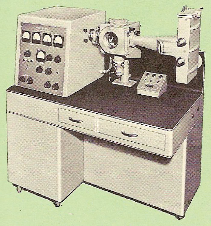
When I entered the University of Michigan in 1946 to undertake my graduate studies, Professor Brockway had just acquired an electron diffraction instrument, shown in Figure 5, manufactured by the General Electric Company. This instrument did not have a self-biased electron gun. Instead, the electron beam was produced by a heated tungsten filament that was located behind an anode with a pinhole in it. The electrons that emerged from this pinhole were focused to a fine spot on the photographic plate by a magnetic lens. Compared to later instruments with self-biased guns, this instrument's electron beam was relatively “gentle,” enough so that it allowed me to study the structure of fatty acid monolayers adsorbed on glass slides for my thesis. One of the many patterns I took with it is shown in Figure 6.

Figure 5: General Electric electron diffraction instrument.

Figure 6: Electron diffraction pattern taken on the GE instrument of Figure 5.
In 1948 The Radio Corporation of America introduced their model EMD-2 electron diffraction instrument, shown in Figure 7. This instrument incorporated the same self-biased electron gun, high-voltage power supply, and vacuum system as the RCA EMU-2 electron microscopes, but with a modified column that contained a moderately large specimen chamber with one magnetic lens above it and another below. With this arrangement it was possible to use the top lens to produce a finely focused beam and the lower lens to magnify the pattern, so that exceptionally good resolution could be achieved. Professor Brockway acquired one of these instruments shortly after they were introduced, and I used it for several years in studies of the carbide phases produced by heat treatment of several heat-resistant alloys. Figure 8 shows an electron micrograph of carbide particles exposed in relief by etching the surface of one of these alloys, and the electron diffraction pattern obtained from them by the reflection method. Using the specially designed comparator shown in Figure 9, it was possible to measure these patterns with sufficient accuracy to permit distinguishing between carbide phases whose unit cell size differed by less than 0.25 Å (for example, TiC with a0 = 4.31 Å from NbC with a0 = 4.40 Å; M23C6 with a0 = 10.63 Å from M6C with a0 = 10.87 Å). Both GE and RCA discontinued manufacturing their electron diffraction instruments in the mid 1960s.

Figure 7: RCA model EMD-2 electron diffraction instrument.

Figure 8: Electron diffraction pattern and micrograph of carbide particles in a heat-resistant alloy.

Figure 9: Device for measuring distances on films of electron diffraction patterns.
Modern electron diffraction. Since that time most routine electron diffraction studies have been carried out in transmission electron microscopes using the selected-area method or the reflection diffraction method (in the projection chamber of the microscope). The principle of the selected-area electron diffraction method was originally discovered in 1936 by J. Boersch, but it was not put into use until it was independently rediscovered in 1944 by J. B. Le Poole, who incorporated the capability into the design of the Philips EM100 electron microscope. I vividly remember an early demonstration of one of these instruments at a meeting of a local crystallographic society. Most of the attendees were amazed to see a diffraction pattern clearly displayed on the viewing screen (nothing like that was ever possible with X rays), and most hoped that it would be possible to use the method for convenient, rapid crystal structure determination. Unfortunately, electrons undergo multiple scattering and are subject to strong absorption, in even tiny crystals, so intensity data accurate enough to make this a generally useful approach cannot be obtained. However, several workers, but notably B. K. Vainshtein at the Russian Academy of Science, successfully applied electron diffraction methods to the determination of the crystal structures of materials such as the clay minerals and micas, which crystallize in thin sheets, and some organic compounds, such as salicylic acid, which crystallize as very thin flakes. For such materials, adsorption and multiple scattering of the diffracted electrons are negligible. This work is described in detail in Vainshtein's book [Reference Vainshtein, Feigl and Spink6].
Although the selected-area electron diffraction capability is a standard feature of all present-day electron microscopes, virtually none are provided with facilities for reflection electron diffraction. Many newer techniques have also been described in the literature in recent years, such as: convergent-beam electron diffraction (CBED), low-energy electron diffraction (LEED), high-energy electron diffraction (HEED), nano electron diffraction, electron channeling diffraction, and electron backscatter diffraction.
Concluding Remarks
In the years immediately following its inception in 1927, electron diffraction was one of the most important topics of study in the field of physics. During those years electron diffraction studies provided a wealth of new information about the structure and properties of a wide variety of materials. They also played an important role in the development of quantum mechanical theories and contributed substantially to the winning of several Nobel Prizes. In recent years electron diffraction methods have become standard tools in studies of the structure of materials. More than twenty books and extended review articles have been written on the subject of electron diffraction. Most of these are listed in a review article I wrote in 1960 [Reference Bigelow and Berl7]. Of course, Thomson and Cochrane's book [Reference Thomson and Cochrane3] is generally considered to give the most pleasant description of early work in the field. At the end of each chapter, Pinsker [Reference Pinsker, Spink and Feigl5] gives an extensive list of references, which, taken together, provide a very thorough coverage of studies undertaken up to the date of publication. Two important more-recent volumes, which discuss work on many more esoteric topics than are mentioned above, are references [Reference Dobson1] and [Reference Goodman2]. I hope that this rather short and somewhat sketchy review will give readers of Microscopy Today an appreciation of the important contributions made by early electron diffraction studies.