Introduction
Complex molecular fluids (CMFs), such as crude oil, surfactants, and liquid crystals, have tremendous impacts on the modern world and are the foundation of several major industries. Unlike simpler liquids, CMFs normally exhibit complex structures (for example, micelles, vesicles, and liquid crystal mesophases) in addition to basic molecular liquids and crystal phases. Figure 1 shows two main types of liquid crystals (LCs) between true liquids and true solids: nematic mesophases (with orientational order only) and smectic mesophases (with orientational order and 1- or 2-D positional order). Organic LCs include thermotropic (typically rod-like molecules with phase transitions driven by temperature) and lyotropic LCs (mixtures of organic molecules and a solvent with ordering transitions governed mainly by concentration) [Reference De Gennes and Prost1]. Because of their complicated structures and the lack of effective nanoscale structural probes for CMFs, detailed understanding of CMF behavior at the molecular level is often surprisingly limited.
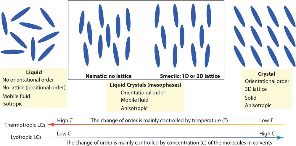
Figure 1 A simplified picture comparing nematic and smectic liquid crystal mesophases to molecular liquid and crystal phases. Low-temperature and high molecular concentration tend to enhance the degree of order in thermotropic and lyotropic liquid crystals, respectively.
Cryogenic transmission electron microscopy (cryo-TEM), recently in the Nobel Prize spotlight for its application in structural biology, has evolved into an essential technique for direct visualization of soft-matter materials at sub-nanometer scale. In cryo-TEM studies, native (often dynamic) structures are quenched into static structures using rapid freezing and observed with low-dose electron beams at cryogenic temperatures. To prepare a cryo-TEM specimen, plunge freezing of a partially electron-transparent thin film is normally the “go-to” technique, as shown in Figure 2a [2]. However, it has been shown that mechanical disturbance (for example, shear force) during the blotting process to remove excess liquid can alter sensitive CMF structures dramatically. For example, wormlike micelles could be modified into individual micelle particles [Reference Clausen3]. In addition, many CMFs including LCs are sensitive to surface and interface effects, making it challenging to preserve the native structure in electron-transparent thin films [Reference Gao4].
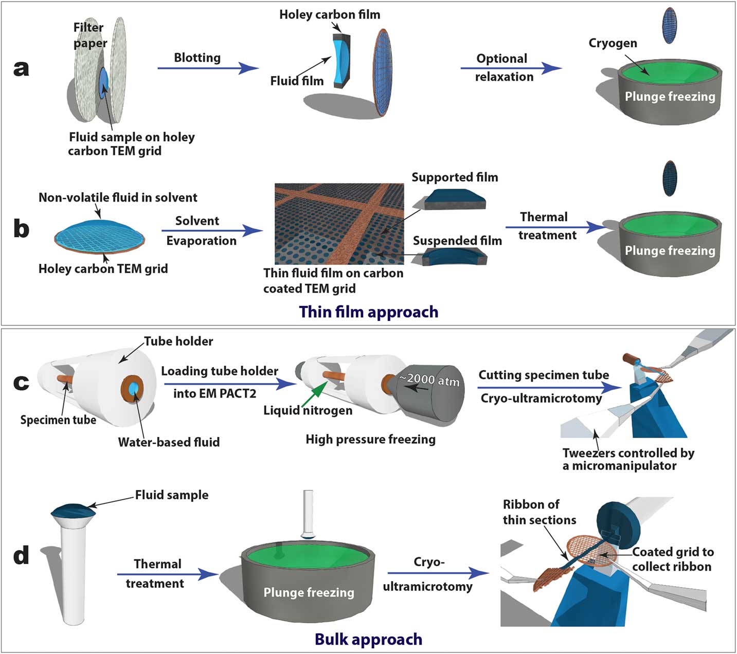
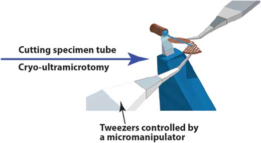
Figure 2 Schematics of “thin film” (a and b) and “bulk” (c and d) approaches to prepare cryo-TEM specimens of soft-matter materials. Procedures (a) and (b) are used to plunge freeze lyotropic LC (a) and thermotropic LC (b) thin films that are partially electron-transparent; (c) and (d) are applied to cryo-sectioning of high-pressure frozen lyotropic (c) and plunge frozen thermotropic (d) “bulk” LC samples using cryo-ultramicrotomy.
In this article, we focus on an alternative “bulk” approach where much thicker samples are rapidly frozen and sectioned by cryo-ultramicrotomy to obtain electron-transparent thin films. We use liquid crystals as a model CMF system and present the general procedures for applying cryo-ultramicrotomy in a variety of LC phases. Some of the better-known applications of cryo-ultramicrotomy can be found in rubber and polymer research and the Tokuyasu immunolabeling technique for sucrose-cryoprotected biological tissues. Very different from those semi-solid materials, LCs and other CMFs are aqueous solutions (lyotropic LCs) or loosely bound molecules (thermotropic LCs). Cryo-sectioning of these super-cooled viscous fluids is similar to that for vitrified aqueous biological samples in the challenging practice of cryo-electron microscopy of vitreous sections (CEMOVIS). The CEMOVIS method combines high-pressure freezing, cryo-ultramicrotomy, and cryo-TEM and makes possible the study of biological samples (such as tissues, cells, and bacteria) in their fully hydrated states [2]. Cryoprotectants are often added to improve vitrification and sectioning quality. High-pressure freezing has also been employed to vitrify lyotropic LCs so the present methods for this type of LC can be considered a part of CEMOVIS. Lyotropic LCs are normally homogeneous phases with high water contents, and additional cryoprotectants can have a greater impact on their structures than on biological samples.
Materials and Methods
Liquid crystals
The LCs examined in this article include thermotropic and lyotropic LCs of different viscosities and various compositions (single and multiple component molecules, chiral dopants, nanoparticles). Table 1 provides basic information about some common LCs presented in this article.
Table 1 Information of common LCs used in this article: names, molecular structures, LC types, and phases.

Thin film specimens
For comparative studies, LC thin film specimens were prepared on holey carbon-coated TEM grids and rapidly quenched in liquid ethane or liquid nitrogen (Figures 2a and 2b). For lyotropic LCs and low-viscosity thermotropic LCs (for example, 5CB), an automatic plunge freezer (FEI Mark IV Vitrobot) was employed to produce the thin film specimens by blotting and rapid plunge freezing. Electron-transparent thin films of thermotropic LCs can be prepared in several ways [Reference Voigt-Martin and Durst5]. Here we used a simple procedure (Figure 2b) consisting of the following steps: dissolving LC in volatile solvent, thin film formation through solvent evaporation, thin film thermal treatment (heating to isotropic phase and then cooling to achieve the desired phase), and manual rapid plunge freezing [Reference Gao4].
Bulk specimens
Our preferred freezing method for bulk specimens employed a Leica EM PACT 2 high-pressure unit to rapidly freeze “bulk” lyotropic LCs (Figure 2c). A high-pressure (~2000 atm) was applied briefly (~20 ms) to the specimen solution sealed in a copper capillary tube (~350 µm inner diameter) prior to the freezing process. This prevents volume expansion, and thus the crystallization of water, so vitrification of the aqueous sample can be achieved [2]. A short section (< 5 mm) was cut from the capillary tube using a special cutter to provide a block of frozen specimen for cryo-ultramicrotomy. For “bulk” thermotropic LCs , a drop of sample a few hundred micrometers thick was applied to a copper or aluminum pin, followed by thermal treatment and plunge freezing (Figure 2d).
Cryo-ultramicrotomy
Figures 2c and 2d also demonstrate how cryo-ultramicrotomy was performed on rapidly frozen “bulk” samples. In this study, we used a Leica UC7/FC7 cryo-ultramicrotome equipped with a micromanipulator and a Crion anti-static device. The cryo-chamber temperature (including knife and sample) should be below the glass transition temperature of the material and was normally between -120°C and -160°C. A cryo-trim diamond knife (Diatome) with a 45° cutting angle and a 20° side angle was used to trim the top of the block into a pyramid shape with a 50 µm height and a 50–200 µm width. Fine sectioning of electron-transparent slices was carried out using cryo-diamond knifes with 35° or 25° cutting angles. A slow cutting rate (typically 1 mm/sec or less), a small cutting width, and a thinner slice were used to achieve easier gliding of slices on the knife surface, which reduced damage. Continuous ribbons were obtained for all the samples described in this article, thanks to a modified procedure demonstrated by Mr. Helmut Gnägi. As illustrated in Figures 2c and 2d, a wedge section of a Cu TEM grid was held by tweezers controlled by the micromanipulator. The starting point of the ribbon was attached to the Cu wedge by an eyelash tool. The attachment was enhanced by the “charge” function of the anti-static device. The manipulator was adjusted to accommodate the growing length of the ribbon during the sectioning process. When the ribbon was comfortably longer than 3 mm, a C-flat holey carbon-coated TEM grid was placed under the ribbon to collect the ribbon. The “charge” function of the anti-static device was used again to enhance adhesion. It should be mentioned that all tools need to be cooled to the cryogenic temperature before touching the ribbons.
Cryo-TEM
The prepared cryo-TEM specimens were stored in liquid nitrogen. For cryo-TEM observation, the specimen was loaded onto a Gatan 626.DH cryo-holder. The cryo-holder with its liquid nitrogen dewar was then transferred into the TEM. Low-dose cryo-TEM observations were performed using an FEI Tecnai F20 TEM equipped with a Gatan Twin-blade anti-contaminator. A Gatan UltraScan 4K camera was used to record images [Reference Gao4]. During the TEM observation process, the specimen was kept below -170°C by liquid nitrogen in the dewar of the cryo-holder.
Results
Thin film approach
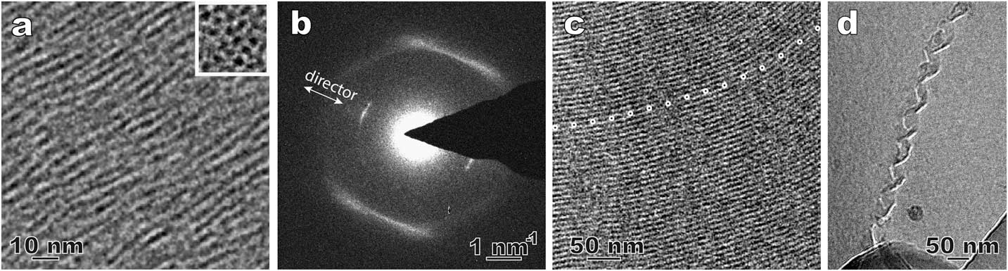
Figure 3 shows a few examples from our recent effort to revisit the method of direct imaging of rapidly frozen thin film specimens (see Figures 2a and 2b). Figure 3a shows the side and top views of the columnar aggregates in a novel lyotropic chromic LC of Ag-containing disk molecules [Reference Pucci6]. The top view of the aggregates (insert image) shows the nature of the nematic arrangement. In a thermotropic nematic LC, the molecules and their arrangement usually cannot be resolved by routine cryo-TEM imaging, but they can be detected by local electron diffraction (Figure 3b). The inner arcs match the long dimension of the bent-core LC molecules and are along the preferred molecular orientation (director). The weak intensity and the absence of higher-order diffraction indicate the lack of a well-defined long-range 1D lattice. The diffuse outer arcs correspond to the short-range order perpendicular to the bent-core molecules. Figures 3c and 3d are cryo-TEM images of a smectic phase [Reference Gao4] and a self-assembled double-twisted helical structure in a blue phase [Reference Gandhi7], respectively. Compared to the traditional freeze fracture replica TEM technique used in LC studies, the cryo-TEM observations in Figure 3 demonstrate certain advantages, such as higher image resolution, examination through the actual material, and the availability of additional TEM techniques (diffraction, spectroscopy, tomography, etc.).

Figure 3 Cryo-TEM results using plunge-frozen LC thin films. (a) Side-view and top-view (inset) of a Ag-containing nematic lyotropic chromonic LC. The dark dots in the top-view are corresponding to the elongated aggregates. (b) A select-area electron diffraction pattern of a bent-core nematic LC; (c) smectic structure in a bent-core thermotropic LC. The dotted line marks curved smectic layers that are parallel to the electron beam. (d) A double-twisted helix in a cholesteric blue phase LC.
Surface effects with thin film approach
The thin film approach (Figures 2a and 2b) is a relatively easy way to prepare cryo-TEM specimens of LCs. In this case, the LC molecular orientation is known to be largely controlled by surface/interface properties. The so-called surface anchoring effect has significant applications in the LCD screen industry, but it imposes challenges on the preparation of thin film specimens representing the LC bulk structure [Reference Gao4]. Figure 4a is a cryo-TEM image of a thin film lyotropic chromonic LC called DSCG (see Table 1), known also as an anti-asthmatic drug. The orientation of the columnar aggregates is strongly influenced by the hole shape and is roughly along the long direction of the hole. Figure 4c shows layered smectic nanoclusters in a bent-core thermotropic nematic LC [Reference Gao4]. The layer number and cluster width vary strongly as a function of the LC film thickness.
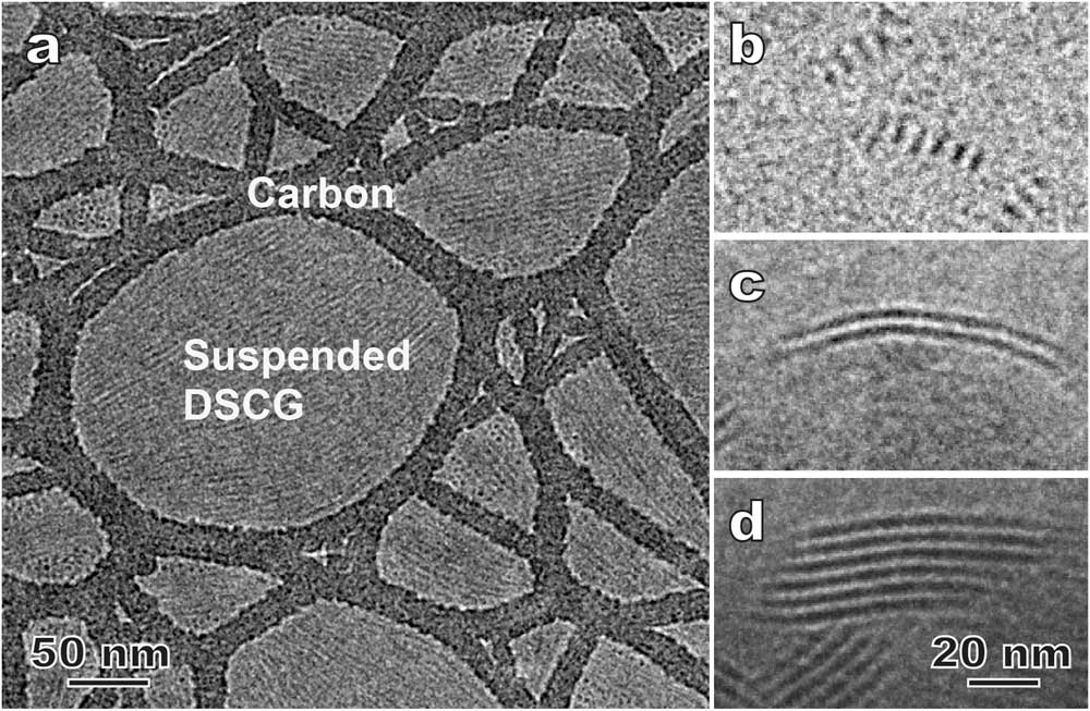
Figure 4 Examples showing the surface effect on cryo-TEM results in LC thin films. (a) Suspended lyotropic chromonic disodium cromoglycate (DSCG) thin film. The elongated aggregates are roughly aligned along the long direction of the holes in the supporting carbon film. (b–d) Morphology of smectic nanoclusters in a bent-core nematic LC varies with film thickness: <100 nm (b), ~150 nm (c), >200 nm (d), respectively.
CEMOVIS of lyotropic chromonic LCs
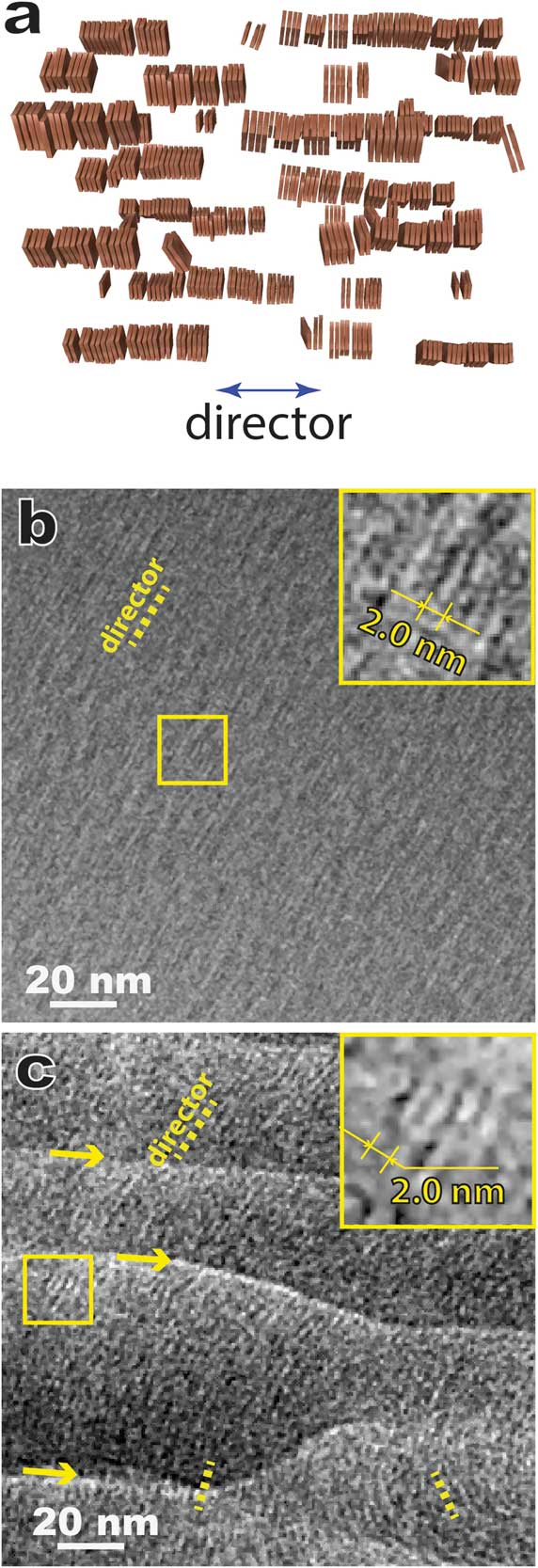
Figure 5 shows results for a model lyotropic chromonic LC, SSY (Table 1) also known as sunset yellow FCF (a food color dye), using the bulk approach of combining high-pressure freezing, cryo-ultramicrotomy, and cryo-TEM, that is, CEMOVIS. In a typical lyotropic chromic LC solution, disk-like molecules stack face-to-face and form columnar aggregates that are the assembly units of the LC structure (Figure 5a). Lyotropic chromonic LCs often feature close distances between aggregates and require high-resolution imaging techniques to resolve the aggregates. Figure 5b is a cryo-TEM image of a ~30 wt% SSY solution prepared by thin film plunge freezing, and Figure 5c shows the same structure prepared by cryo-ultramicrotomy. The viscous high-concentration solution made it challenging to achieve an electron-transparent thin film using the Vitrobot plunge freezer. But in some local regions, we could still observe the side-views of straight aggregates with ~2.0 nm spacing (Figure 5b insert). In general, cryo-sectioned specimens lead to sufficient image quality for identifying the side-view (Figure 5c) and top-view of the aggregates (not shown). Another intriguing feature revealed by CEMOVIS is the local orientation variation of the aggregates (Figure 5c), which is considered to be more realistic for the bulk material. But some pronounced specimen damage (crevasses, knife marks, compression, etc.) due to sample-knife interaction can often be seen (Figure 5c) and leads to a lower imaging quality at high resolution compared to the results from thin film plunge freezing. This current disadvantage of the bulk approach can be partially overcome by adding a cryoprotectant (for example, dextran) to the solution [2].

Figure 5 (a) A schematic of nematic lyotropic chromonic LC. (b) Cryo-TEM of plunge-frozen nematic 6-hydroxy-5-[(4-sulfophenyl)azo]-2-naphthalenesulfonic acid (SSY) thin film. The inset is a magnified image of the local area marked by the square. (c) CEMOVIS of the same nematic SSY solution, showing variation of the local orientation of the aggregates. The arrows indicate crevasses introduced by cryo-ultramicrotomy. The inset is a magnified image of the local area marked by the square. The dotted yellow lines in (b) and (c) indicate the orientations of local directors.
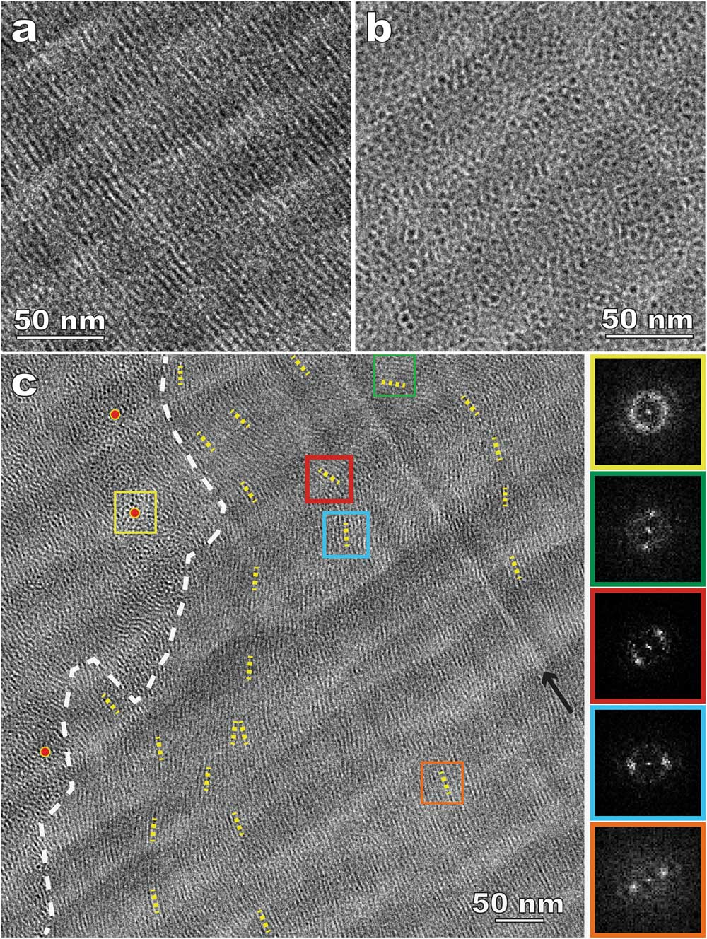
Figure 6 shows CEMOVIS images of 15% DSCG with 10% dextran. Dextran, a commonly used cryoprotectant to facilitate the vitrification process, was added to avoid water crystallization and to improve the cryo-sectioning quality. Columnar aggregates parallel (Figure 6a) and perpendicular (Figure 6b) to the specimen surface can be identified more easily because of considerably reduced sectioning damage compared to the results without dextran (Figure 5c). In addition, the improved imaging quality leads to better visibility of domains with random aggregate orientations and other detailed structures. Figure 6c shows bending and director variation in the aggregates, especially near domain boundaries. It should be mentioned that cryoprotectants act as depletion agents and compete for water. Polarized light microscopy (PLM) was employed to understand the impact of cryoprotectants on LC phase transition and to verify that the cryo-TEM results can still represent the native structure [Reference Gao4].

Figure 6 CEMOVIS of a nematic disodium cromoglycate (DSCG) solution with added dextran. (a) and (b) Side- and top-views of the columnar aggregates (dark lines and dots, respectively); (c) variations of aggregate orientation. The white dashed line indicates a domain boundary. The short yellow dotted lines track local aggregate orientations (directors). Red dots are placed in the areas where the aggregates are parallel to the electron beam. The FFT patterns on the right side correspond to the areas enclosed by squares in the same outline colors. The black arrow indicates a knife mark (bright line).
Liquid crystal–nanoparticle composites
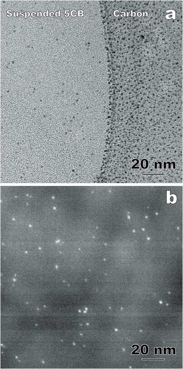
Nanoparticle-doped LCs is an emerging area generating both fundamental and application interest. The physical properties of LCs and nanoparticles, including LC molecular alignment and metal nanoparticle surface plasmon resonance, can be tuned through the interaction between the anisotropic LC fluids and doped nanoparticles [Reference Xue8]. One of the challenges in LC-nanoparticle composites is that nanoparticles often aggregate into clusters [Reference Gao4]. Recently, photoresponsive azo thiol was used to passivate Au nanoparticles in 4-Cyano-4’-pentylbiphenyl for a homogeneous dispersion [Reference Xue8]. Figures 7a and 7b show comparative cryo-TEM results of the composite using thin film and bulk approaches, respectively. In the suspended 5CB thin films (including the sectioned slice in Figure 7b), the doped Au nanoparticles (1–3 nm in diameter) are distributed randomly without agglomeration, which is a key determining factor for the composite properties including a stable reversible alignment control of 5CB molecules using light irradiation [Reference Xue8]. However, the carbon supporting film used in the thin film approach exhibits a strong attraction to the Au nanoparticles (Figure 7a). As a result, the distribution and concentration of Au nanoparticles in the suspended 5CB films can be modified during the blotting process.

Figure 7 Comparative cryo-TEM images of LC-nanoparticle composites with gold nanoparticles incorporated into 4-Cyano-4’-pentylbiphenyl (5CB). (a) Thin film approach (plunge freezing using the FEI Vitrobot) imaged in bright-field TEM mode. (b) Bulk approach (plunge-freezing and cryo-sectioning). Annular dark-field (Z-contrast) STEM imaging improves the visibility of the nanoparticles within the liquid crystal. The contrast variation in the background is corresponding to the imperfection caused by cryo-ultramicrotomy.
Cholesteric liquid crystals
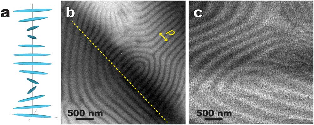
Cholesteric (that is, chiral nematic) LC molecules form 2-dimensional nematic-like thin layers. Molecules in each layer orient along a common preferred direction (director). The directors of different layers twist to form a helical pattern (Figure 8a). Figures 8b and 8c show typical cryo-TEM images of the “fingerprint” texture of a cholesteric LC, namely a chirally doped E7 (a LC mixture of several cyanobiphenyls with long aliphatic tails) [Reference Li9], prepared by thin film plunge freezing (Figure 2b) and bulk cryo-ultramicrotomy (Figure 2d), respectively. The distinct alternating contrast in Figure 8b corresponds to the helical twist. Figure 8b also indicates that the surface anchoring effect tends to have the helix axis lying on the supporting carbon film. This simple geometry makes it convenient to determine the pitch of the helical twist (roughly 2 times the periodicity of the distinct alternating pattern). In contrast, the sectioning direction is normally at an angle to the helical axis in the bulk approach without pre-alignment (Figure 8c), which often results in larger contrast periodicity.

Figure 8 Comparative cryo-TEM images of a thermotropic cholesteric (chiral nematic) LC (chirally doped E7). (a) A schematic showing the director twist in cholesteric LC; (b) plunge-frozen thin film supported by thin carbon film. The area on the right side of the dashed line is strongly influenced by the surface anchoring effect. A pitch (p) of the helical twist is illustrated. (c) Bulk approach using cryo-sectioning where the sectioning direction was at an angle with the helical axis.
Twist-bend nematic phase of liquid crystals
Figure 9 shows another interesting example: twist-bend nematic phase (Ntb) [Reference Borshch10]. This “new” nematic structure has been long predicated in addition to the earlier normal nematic (Figure 1) and chiral nematic (Figure 8a) LCs, but was only confirmed recently thanks to combined freeze fracture TEM and cryo-TEM [Reference Borshch10]. A major difference between chiral nematic and twist-bend nematic phases is that the former has a 90° angle between twist axis and the directors, whereas the latter has a smaller angle (Figure 9a). In addition, there is no modulated density but only a 1D modulation of orientation order [Reference Gao4,Reference Borshch10]. Liquid crystal molecules, typically rod-like or long bent molecules, tend to fracture along their long directions, so the orientational ordering can be revealed by the surface-sensitive freeze-fracture TEM as a clear 1D modulation of ~8 nm in periodicity in 1”,7”-bis(4-cyanobiphenyl-4’-yl)heptane (CB7CB) (Figure 9b). In contrast, cryo-TEM of cryo-sectioned specimens shows homogeneous contrast (Figure 9c). Note similar procedures (plunge freezing, sample dimensions, etc.) were used in the freezing process before both the fracture and the cryo-sectioning. The comparative result (Figures 9b and 9c) indicates that CB7CB has 1D orientational order, but no modulated density, which provides one of the strongest evidences of the existence of the Ntb phase so far [Reference Gao4, Reference Borshch10].
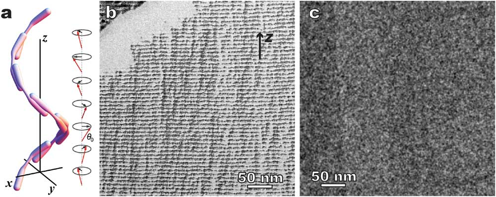
Figure 9 Twist-bend nematic phase - 1”,7”-bis(4-cyanobiphenyl-4’-yl)heptane (CB7CB). (a) A schematic of the twist-bend nematic structure. Comparative microscopy methods: (b) freeze fracture TEM showing well-defined 1D modulation, and (c) cryo-TEM of cryo-sectioned CB7CB showing no ordered structure. The arrow in (b) indicates the helical axis (z).
Discussion
Currently, there are two main challenges facing the recommended “bulk” approach specimen preparation method for cryo-TEM of LCs and other CMFs. First, the freezing of “bulk” samples may not be straightforward. The slower cooling rate further away from the sample surface may introduce undesired phase transitions, especially in thermotropic LCs. This is a lesser problem for lyotropic LCs since high-pressure freezing can be used. In addition to plunge freezing, other techniques are available to achieve faster cooling rates, for example, slam freezing and jet freezing [2]. But plunge freezing is the most convenient one, and it is often sufficient for thermotropic LCs because of the slower diffusion of the large molecules compared to water-containing solutions, especially for those samples possessing super-cooling properties. Second, the cryo-sectioning of frozen LCs or CMFs in general can be challenging at this point. The quality of the sectioned cryo-TEM specimens may depend to a large degree on the skill and experience of the operator. Cryo-ultramicrotomy of frozen CMFs is a dry-cutting process of a high-viscosity fluid using a sharp diamond knife. The sectioned thin slices need to glide on the knife surface. Also, the frozen fluids have no strong internal bonding and can flow and deform depending on external force. During cutting, the knife edge creates high local pressure, which introduces inevitable compression along the sectioning direction and thickness increases. Crevasses occur when the fracture limit of the sample is exceeded. In addition, many inhomogeneities exist including irregularities and damage at the knife edge, imperfections and irregular friction of the knife surface, and inhomogeneous sample, just to name a few [2]. These factors can contribute to various image artifacts (for example, knife marks and varying section thickness). As a result, the imaging quality from the sectioned specimens is normally not as good as that from the thin film approach. An optimized cryo-ultramicrtomy condition is a key for high-resolution imaging of cryo-sectioned LC specimens.
Recent instrumentation developments in several areas present a promising future for cryo-sectioning. For example, single/double manipulators [Reference Studer11], the anti-charging device, and improved diamond knives have helped the quality of cryo-ultramicrotomy. In addition, focused ion beam sectioning operating at cryo-temperatures (cryo-FIB) may be a promising alternative to cryo-ultramicrotomy. Cryo-FIB advantages may include less sectioning damage, more flexibility in sectioning direction, more accurate access to the different depths of the frozen sample, and better utilization of the surface layer [Reference Wang12].
We also demonstrated here that the thin film and bulk approaches to cryo specimen preparation can be complementary, as can cryo-TEM and replica freeze-fracture TEM. The advantages provided by the thin film approach (straightforward freezing, simple geometry, high imaging quality, etc.) and freeze fracture TEM (surface sensitivity, etc.) can be very useful when used properly. A combination of the above techniques is recommended for challenging systems.
Conclusion
In this article we present procedures and representative results on the “bulk” approach for studying nanoscale structures in a range of liquid crystals. The “bulk” approach, combining rapid freezing of complex molecular fluids, cryo-sectioning, and cryo-TEM, can effectively minimize the surface/interface effects that have been a major limitation of the more convenient thin film approach cryo-TEM. Thus, the bulk approach reveals more precisely the native structure. We believe that the bulk approach can become a powerful alternative to the thin film approach in CMF studies, especially with the continuous development of rapid freezing and cryo-sectioning techniques.
Acknowledgements
The TEM-related experiments were carried out at the cryo-TEM lab of the Liquid Crystal Institute, Kent State University. We thank Dr. Lu Zou, Mr. Helmut Gnägi, Dr. Liang-Chy Chien, Dr. Jeoung-Yeon Hwang, Dr. Antal Jákli, Dr. Cuiyu Zhang, Dr. Oleg D. Lavrentovich, Dr. Heung-Shik Park, Dr. Young-Ki Kim, Dr. Volodymyr Borshch, Dr. Shuang Zhou, Dr. Quan Li, Dr. Yannian Li, Dr. Chenming Xue, Dr. Daniela Pucci, Dr. Alessandra Crispini, Dr. Georg H. Mehl, and Dr. Wolfgang Weissflog for technical assistance, LC samples, and useful discussions.