


Introduction
The field of microscopy is currently experiencing a proliferation of novel designs and architectures that unlock improved imaging performance. However, such design efforts typically operate within a well-known trade-off space. For example, as the resolution of a microscope increases, the demands placed on the lens design become stricter, which leads to a smaller imaging field-of-view (FoV) and depth-of-field (DoF). Another drawback of conventional imaging techniques is the loss of phase information, which is crucial for observing unstained specimen material such as in vivo tissues and cells. These limitations (among many others) have been historically addressed in microscopy through various and oftentimes ingenious modifications. For example, gigapixel images can be obtained by adding a scanning sample stage, and transparent samples can be clearly observed with the addition of a phase ring inside the microscope objective lens.
Today, an increasingly popular way to address such shortcomings is by co-designing new image post-processing software with updated hardware, which can unlock unique performance enhancements within the modern digital microscope. In the first of this three-article series [Reference Zhou1], we introduced an example “computational imaging” technique termed Fourier ptychography (FP), which uses this co-design strategy to overcome a variety of limitations faced by standard microscopes. FP captures multiple images of a specimen or object under different angles of illumination. These images are then fused into a final image with a higher resolution than that of the native imaging system. As explained in Article 2 [Reference Loetgering2], since the phase of the incident light is not measured, FP employs a “phase-retrieval” algorithm that jointly estimates such unmeasured quantities during data post-processing. The result is a large-area, high-resolution image that also contains quantitative phase information at each resolved pixel.
In this article, we focus on the most salient practical benefits and applications of FP that we anticipate will eventually impact future microscope design and development. Empowered by computational algorithms, FP offers a unique solution to high-resolution image formation, where issues caused by a narrow FoV and shallow DoF are common. Through the combination of low numerical aperture (NA) lenses and digital refocusing, FP can maintain a high lateral resolution over a large FoV and DoF. Combined with digital correction of microscope imperfections (for example, optical aberrations), FP provides unprecedented imaging quality and digitally tunable illumination contrast mechanisms across extremely wide image areas. While FP is proving itself as a useful standalone light microscope imaging platform, its variable-illumination methods are now being coupled with new image post-processing tools, and it is also finding applications outside the visible light regime. In the rest of this article, we summarize these trends with an eye toward future practical use cases.
Gigapixel Imaging for Digital Pathology
Most microscope-centered tasks within a pathology lab require the ability to observe patient specimens at high resolution over a large area. As many pathologists begin to adopt a digital workflow, a growing number of “whole-slide scanning” microscopes are now available to sequentially acquire images of fixed tissue, blood smears, and cytological material via step-and-repeat acquisition. As high-magnification optics (20×–40×) are typically required for image production, scanning across a 1 cm2 area often requires several minutes. Given the shallow DoF of such objective lenses, constant refocusing is required during scanning, which adds to the cost and complexity of the imaging system.
In contrast, FP can obtain wide-FoV, high-resolution images, without the need of any moving parts or high-NA optics (Figure 1a). Compared to their high-resolution counterparts, the low-resolution microscope objective lenses utilized by a FP microscope provide the advantages of a long-working distance, large DoF, and significantly lower cost. Even if cost is not a problem, the same scanning principles can be applied to FP for extremely large sample imaging. Such features make FP well-suited for high-throughput imaging for digital pathology applications.

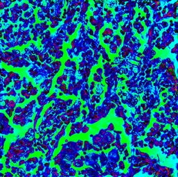
Figure 1: In FP, multiple low-resolution images are collected using angular illumination (a). Once the images are algorithmically combined into a sample spectrum, its Fourier transformation yields a wide-field, high-resolution image (b). Within the zoomed-in section in (c), both amplitude and quantitative phase information are reconstructed. Additionally, digital manipulation of the reconstructed spectrum provides other forms of contrast, such as darkfield or differential phase contrast.
Enhancing Image Contrast
A broad range of specimens lack sufficient contrast when viewed directly under a microscope. FP's use of light emitting diode (LED) array illumination offers multiple direct paths to improve image contrast (Figure 1). It is well known that illuminating a microscopic sample from different directions allows one to observe unique image contrast mechanisms, ranging from brightfield to darkfield. Unique contrast mechanisms may also be accessed via physical modifications within the microscope imaging path itself. Rather than changing illumination direction, a Zernike microscope uses a phase ring to retard part of the illumination to yield images with increased contrast, while light stops are routinely placed in the illumination path to achieve darkfield contrast.
While these various microscope enhancements seem surprisingly different, in essence all operate by modifying the scattered light passing through a microscope. In FP, such scattered information is accessed directly after its computational reconstruction. FP's reconstructed complex spectrum represents diffracted fields captured across a wide range of illumination angles. Hence, through selective spectrum filtering, as illustrated in Figure 1c, FP can digitally mimic various modes of contrast enhancement, ranging from direct phase information to differential phase contrast or arbitrarily selectable darkfield arrangements, all from the same acquired FP dataset and without any additional hardware. We note here that such contrast mechanisms can be unlocked at relatively high speeds (sub-Hz), despite FP's need for time-sequential illumination, by lighting up multiple LEDs in parallel during image acquisition [Reference Tian3].
Accurate Measurement of Thick Specimens
Many modern microscopes struggle with focusing issues caused by a shallow DoF, which scales inversely with the square of the objective lens numerical aperture. Hence, high-resolution optics are best suited for optically thin, flat samples, whose thickness approaches submicron scales for diffraction-limited imaging. Mechanical scanning along the optical axis is routinely used by many widefield microscopes to acquire in-focus images of non-flat specimens and to access 3D information. As noted above, the use of low-NA optics in FP microscopes circumvents many of the issues caused by a shallow DoF (Figure 2a), while the imaging procedure retains the high-axial resolution of high-NA optics (Figure 2b).

Figure 2: (a) Low-NA optics tend to have a significantly wider DoF compared to (b) high-NA optics. (c) Achieving both wide DoF and high resolution is typically achieved by mechanically scanning and through-focus image capture. (d) In contrast, the reconstructed image in FP has a narrow DoF, but with digital refocusing can access other slices within the low-NA lens DoF.
With FP, it is also possible to digitally refocus a single image reconstruction through multiple axial planes, which can mimic the effect of axially scanning a high-NA objective during acquisition of multiple images (Figure 2c). Although standard FP obtains a high-resolution complex-valued reconstruction at a single focal plane, it is possible to digitally propagate its reconstruction from one longitudinal plane to the next based on the theory of light diffraction, which provides access to a large DoF (Figure 2d). While both scanning microscopy and FP unlock the ability to obtain an extended DoF through time-sequential image capture, no moving parts are necessary in FP. The ability to maintain high-axial resolution within thick samples makes FP ideal for applications such as cytology, where cells tend to aggregate in large clusters, necessitating a wide DoF [Reference Liang4].
FP typically assumes that reconstructed samples are thin (that is, obey the projection approximation). Once the sample thickness exceeds the DoF, scattered light from out-of-focus features is also collected. While such light is often considered a nuisance in microscopy, it can carry important information about 3D sample structure. Several extensions of FP have been developed to utilize this information to produce 3D tomographic reconstructions of a specimen's index of refraction. One example is FP diffraction-tomography [Reference Konda5], while another approach models a thick sample as a sandwich of multiple thin slices (that is, a “multi-slice” approximation) for reconstruction [Reference Konda5]. Such methods do not require additional hardware (such as an axial translation stage) and instead rely purely on additional computational complexity.
Digital Correction of Hardware Imperfections
While the original reconstruction algorithms developed for FP required a well-calibrated microscope for effective image reconstruction, new extensions of the FP algorithm can now digitally address various hardware imperfections. Imaging aberrations are one of the most important imperfections that FP algorithms now routinely address. Specifically, thanks to the phase-sensitivity of the FP reconstruction process, spatially varying lens aberrations can now be directly characterized and removed from images during their reconstruction (Figure 3). As a result, image quality no longer has to suffer from the use of lower-cost optics, and the recovered aberrations can also be used for lens characterization purposes within lens metrology.

Figure 3: To computationally account for and remove spatially varying aberrations, FP methods first (a–b) divide the recorded image into many small segments; over each one, aberrations can be assumed constant. (c) For each segment, a guess is made for the object and pupil aberrations. (d) Once reconstructed, segments are gathered and stitched together into (e) a full reconstructed image composite. (f) Each segment across the full FoV maintains a uniquely corrected optical aberration map.
To avoid tedious instrumentation calibration, FP algorithms have also evolved to automatically deal with less-than-perfect imaging conditions and hardware misalignment issues. Algorithms are also available to account for the partial spatial and temporal coherence of the employed LEDs used for illumination. However, care must be taken when designing an imaging system to minimize the computational burden of such automated alignment and correction procedures and to ensure effective algorithm convergence. Coupled with the ability to digitally refocus (see above), FP's aberration and misalignment correction procedures provide a compelling means to relax the tight tolerances of objective lens and optical system manufacture.
Extracting Additional Information
So far, we have considered alteration of the amplitude and phase of light after passing through the specimen. However, light has other measurable properties, such as its polarization and wavelength, which can also be recovered within the FP framework. For example, anisotropic specimens are routinely viewed between crossed polarizers. As these polarizers are rotated, the specimen's interaction with polarized light can provide unique insights into its molecular composition. With FP, it is also possible to capture illuminated images of the polarization response of a specimen of interest and subsequently reconstruct its polarization properties, as well as polarization-dependent optical aberrations [Reference Dai6]. Compared to other approaches, FP provides such quantitative information without the use of interferometric equipment.
Fluorescence is another widely utilized microscope modality. As fluorescence is an incoherent emission process, it generally remains unchanged with respect to illumination angle and thus does not fall within the FP image formation model. Fortunately, fluorescence and FP can be used synergistically. For example, fluorescence images can be improved through deconvolution by the reconstructed spatially varying point spread function using FP. Additionally, patterned plane wave illumination has been shown to provide sufficient algorithmic constraints to reconstruct wide-field, high-resolution fluorescence images [Reference Dong7].
Finally, information extraction beyond the known imaging models is also possible with novel machine learning (ML) methods. To enhance low-quality images with ML, various supervised learning algorithms have been trained on high-resolution ground truth reference data. FP lends itself naturally to such methods, as its low-resolution images can be directly paired with high-resolution reconstructions and contain information regarding high-resolution specimen features. With digital refocusing, FP can also produce focal stacks, which have been used to achieve ML-driven in silico fluorescence staining of unstained specimens [Reference Waibel and Tetko8]. With its recent coupling with ML algorithms, FP has already benefited from faster image acquisition and improved reconstruction quality. Given the early stage of such research efforts, more applications of ML are expected to impact FP in the coming years.
Imaging Outside of the Visible Spectrum
FP is not limited to the visible light spectrum and can be used with other source wavelengths including infrared, ultraviolet, X-rays, and electrons. Imaging outside the visible spectrum comes with many challenges, such as lens manufacturing and the generation of suitable illumination. Poor lens quality and limited light coherence are commonly encountered in microscopy, making FP attractive for imaging at other wavelengths.
For example, X-rays tend to have high penetration depths in dense materials, including focusing optics, which is why low-NA optics are commonly utilized (Figure 4a). Given the difficulties of X-ray lens manufacturing, FP is ideal for applications involving low-quality optics. In the past decade, X-ray imaging with synchrotrons has widely adopted conventional ptychography, a predecessor of FP. Importantly, most high-resolution X-ray imaging applications with synchrotrons tend to avoid the use of imaging optics. However, compared to ptychography, FP tends to perform better when using lower-coherence light sources [Reference Horstmeyer and Yang9]. With the advances of table-top X-ray sources (for example, metal-jet and high harmonic generation), sufficient coherent flux is available for ptychographic imaging [Reference Loetgering10]. While table-top X-ray sources have only been used for conventional ptychography, they are ideally suited for FP. However, difficulties in generating angularly varying X-ray illumination may necessitate developments of efficient scanning by physically moving the lens and detector [Reference Wakonig11] as illustrated in Figure 4b and 4c.

Figure 4: Fourier ptychography with X-rays and electrons. (a) Accurate focusing of X-rays is difficult, which limits refractive X-ray lenses to low-NA imaging. (b-c) Precisely steering the direction of X-rays over a large angular range is difficult, which is why aperture scanning techniques are used. (d) Electromagnetic lenses are used for focusing and collection of electrons, making it possible to vary the illumination angle of the electron beam, (e) in principle allowing for FP reconstruction of EM data.
Within electron microscopy (EM), the combination of magnetic lens aberrations, experimental instabilities, and illumination coherence have provided an obstacle in achieving atomic resolution. With novel aberration correctors, the resolution of EM has improved significantly. Tilt-series reconstruction methods [Reference Haigh12], where angularly illuminated images (Figure 4d and 4e) were used to synthesize a wider Fourier space, have also led to resolution gains. Such tip-tilt illumination methods mirror the angular illumination used in FP, but without its modern algorithmic inversion techniques. By incorporating the aberration-correction procedures currently offered by FP, we anticipate that further enhancement of EM image quality may be on the horizon, which is still awaiting an experimental demonstration.
Summary
From the point of experimental implementation, FP is extremely simple. All that is required is an angular illumination source such as an LED array. Its complexity is instead hidden from the eyes of microscopists and placed onto extensively developed computational algorithms. While fields such as machine learning are also offering digital image enhancement by “guessing” what the correct output should be, FP is based upon correct and well-understood analytical image formation models. Inversion of such models by using captured images can produce gigapixel-sized images of both amplitude and phase, together with the removal of optical aberrations and the ability to acquire 3D information. In essence, FP offers a simple, cost-effective solution to unlock resolution-enhanced, wide-FoV imaging. Given the young age of the technique, it is still at its infancy regarding commercial use. As talented entrepreneurs notice its potential, we anticipate that various manifestations of FP's basic principles will emerge within future commercial imaging products.


