


1. Introduction
A helicon plasma (HP) source generates high-density plasma using a several kilowatt radio frequency (RF) power supply with an external magnetic field and a few Pascals of gas pressure. The external magnetic field ranges from a few milliTesla to hundreds of milliTesla under various configurations, such as uniform, divergent and convergent (Shinohara Reference Shinohara2023, p. 7). The antenna structure is another critical factor that affects the plasma generation and wave propagation characteristics, such as the generation of the high azimuthal mode (Shinohara, Tanikawa & Motomura Reference Shinohara, Tanikawa and Motomura2014). An HP source with a flat spiral antenna, which is one of the flat-type antennae, achieved plasma generation of 74 cm in diameter (Shinohara et al. Reference Shinohara, Motomura, Tanaka, Tanikawa and Shamrai2010). Because of its dense plasma and wide range of plasma and operational parameters, HP sources are used for various applications, for example, in plasma thrusters (Squire et al. Reference Squire, Chang Díaz, Glover, Jacobson, Chavers, Bengtson, Bering, Boswell, Goulding and Light2003; Takahashi Reference Takahashi2023), semiconductor processors (Tynan et al. Reference Tynan, Bailey, Campbell, Charatan, de Chambrier, Gibson, Hemker, Jones, Kuthi, Lee, Shoji and Wilcoxson1997), fundamental research devices (Kawachi et al. Reference Kawachi, Sasaki, Nishizawa, Kosuga, Terasaka, Inagaki, Yamada, Kasuya, Moon, Nagashima and Fujisawa2023) and nuclear fusion-related research, such as that on plasma–wall interaction (Zhang et al. Reference Zhang, Huang, Jin, Wu, Zhuge and Ji2018; Rapp et al. Reference Rapp, Lumsdaine, Beers, Biewer, Bigelow, Caneses, Caughman, Goulding, Kafle, Lau, Lindquist, Piotrowicz, Ray and Showers2019). Typical linear devices for nuclear fusion-related research generate plasma with electron density $n_{{e}}$ and temperature $T_{{e}}$
 of $10^{19}$
 m$^{-3}$
 and up to 10 eV (Ohno Reference Ohno2017). To advance this research, a new experimental platform is required that can generate higher electron densities of approximately $10^{20}$
 to $10^{21}$
 m$^{-3}$
 and electron and ion temperatures above 100 eV in the steady state (Ohno Reference Ohno2017). In addition, a large plasma diameter under a strong magnetic field is required to investigate real-scale commercial applications or a demonstration (DEMO) fusion reactor condition (Asakura et al. Reference Asakura, Hoshino, Kakudate, Subba, You, Wiesen, Rognlien, Ding and Kwon2023).
The pilot GAMMA PDX-SC, which is a superconducting magnetic mirror device, is under development at the plasma research centre of the University of Tsukuba. It aims to contribute to developing the critical component in the DEMO reactor called the divertor. The pilot GAMMA PDX-SC has three sections: the plasma generation, confinement-heating, and end-loss plasma regions. We focused on high-density ($10^{19}$ m$^{-3}$
 ) and large-diameter (approximately 10 cm) plasma generation. As a first step of development, we conducted a plasma generation experiment on a testbed device called the Compact Test Plasma (CTP) device using the same plasma source as that for the pilot device. A novel HP source with a two-turn flat-loop antenna was developed. This antenna has the same geometry as that of the flat spiral antenna and with it a large-diameter plasma is expected. In addition, the radiation pattern can be controlled by changing the RF high-voltage feeding and ground points of the antenna. The electron density profile is affected by the RF radiation (Shinohara et al. Reference Shinohara, Tanikawa and Motomura2014). The plasma diameter changes depending on whether outer or inner loops are used (Shinohara et al. Reference Shinohara, Tanikawa and Motomura2014), and the density changes depending on the feeding point (Shinohara & Tanikawa Reference Shinohara and Tanikawa2005). However, scientific and engineering problems should be overcome, such as density saturation phenomena owing to neutral particle depletion (Magee et al. Reference Magee, Galante, Carr, Lusk, McCarren and Scime2013), heat load problems in long-time steady-state discharge (Thakur et al. Reference Thakur, Simmonds, Caneses, Chang, Hollmann, Doerner, Goulding, Lumsdaine, Rapp and Tynan2021) and optimization of plasma generation in non-uniform magnetic fields (Mori et al. Reference Mori, Nakashima, Baity, Goulding, Carter and Sparks2004). In this paper, we report the plasma properties with various magnetic field configurations and discuss how to improve the performance and future development strategies.
2. Experimental set-up
An HP plasma source was developed on the CTP device, which successfully generated argon plasma (Seto et al. Reference Seto, Ezumi, Miyauchi, Shigematsu, Okamoto, Takahashi, Takanashi, Hirata, Togo, Sakamoto, Furukawa and Shinohara2023). Figure 1 shows a schematic of the CTP device. The CTP device has three vacuum gauges; one is a capacitance gauge in the generation region, and the other two are a capacitance gauge and cold cathode gauge in the diagnostics region. The background pressure is approximately $10^{-5}$ Pa.
Pa.
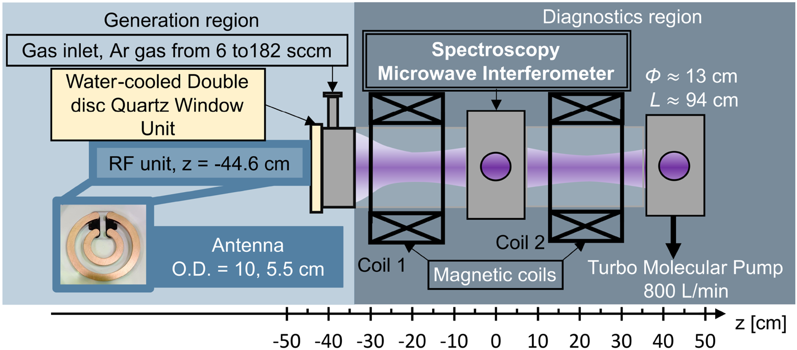
Figure 1. Schematic of the CTP device.
The diagnostics region comprises two magnetic field coils ($z=\pm {21}$ cm) and a measurement port ($z=0$
 cm). Each coil has 384 turns and the applied 65 A maximum current generates a static magnetic field. Figure 2 shows the magnetic field strength along the axis of the CTP device. The radial magnetic profile is almost constant throughout the vacuum vessel. We varied four conditions of coil currents to change the magnetic field configuration, as shown in figure 2. In this paper, ‘(i) 65 A-65 A’ refers to the case (i) with the coil current of coil1 ($z=-21$
 cm) equal to 65 A and that of coil2 ($z=+21$
 cm) equal to 65 A. The radial-line-integrated emission intensities were observed using a spectrometer (AvaSpec-ULS4096CL-EVO-UA-10) placed in the measurement port. At 90$^{\circ }$
 from the radial line observed using the spectrometer, the radial-line-averaged electron density $\overline {n_{{e}}}$
 was measured using a 17.5 GHz microwave interferometer. Figure 3 shows a schematic of the 17.5 GHz interferometer system with a cutoff density of $3.8\times 10^{18}$
 m$^{-3}$
 , which is a homodyne system using a phase-locked oscillator and an in-phase and quadrature mixer (IQ mixer) (direct conversion or zero-intermediate frequency receiving system) (Podolsky, Khomenko & Macheret Reference Podolsky, Khomenko and Macheret2018). Both the transmitting (Tx) and receiving (Rx) antennae are pyramidal horns without focusing elements. The 3 dB beamwidth of the Tx antenna is 20$^{\circ }$
 in the vertical direction. In the vertical direction at the centre of the plasma, the beam spot size is approximately 8 cm ($r\approx \pm 4$
 cm), and the most divergent ray (from the main beam) accepted by the receiving antenna crosses at $r\approx \pm 1$
 cm, neglecting the effect of refraction and scattering of the beam. The phase shift owing to the presence of plasma was determined employing a technique similar to that described in Podolsky et al. (Reference Podolsky, Khomenko and Macheret2018) using in-phase (I) and quadrature-phase (Q) signals from the IQ mixer.
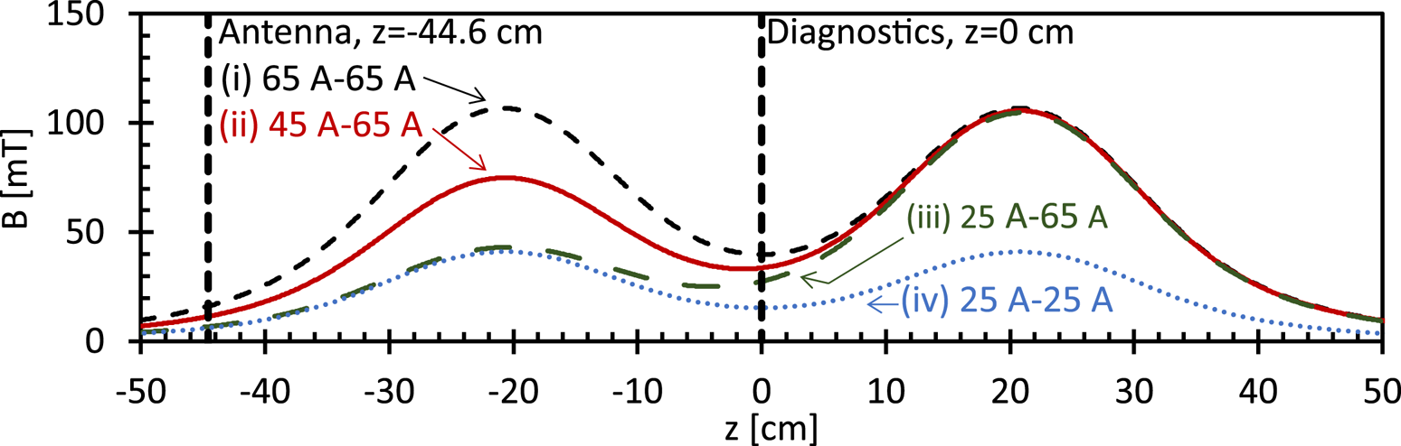
Figure 2. Magnetic field strength profiles on the $z$ -axis of the CTP. The Coil1 ($z=-21$
 cm) and Coil2 ($z=+21$
 cm) currents are (i) 65 A-65 A, (ii) 45 A-65 A, (iii) 25 A-65 A, (iv) 25-25 A.
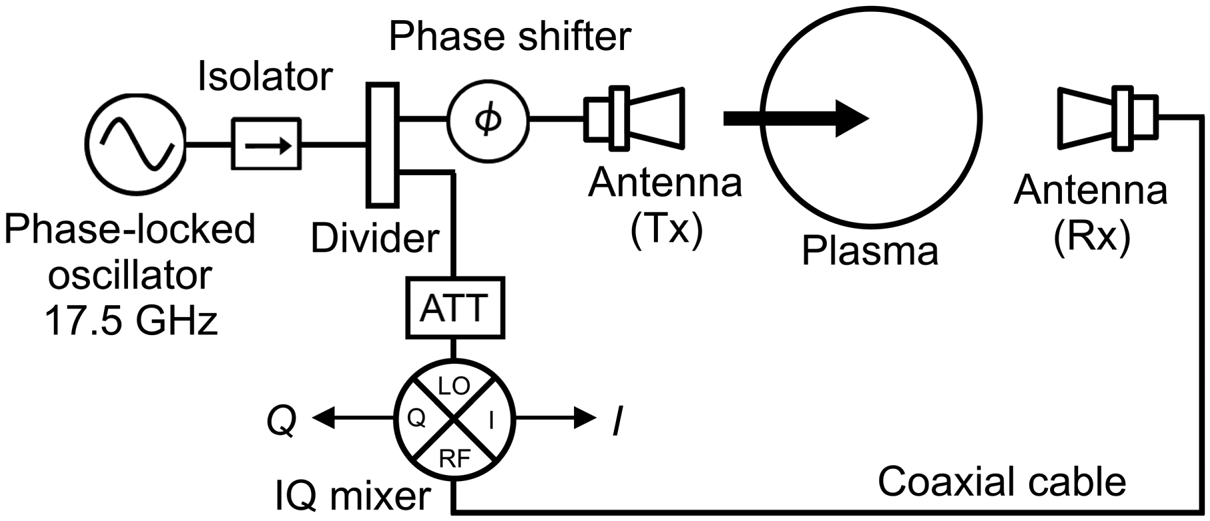
Figure 3. Schematic of the microwave interferometer system on the CTP device.
The generation region consists of a two-turn flat-loop antenna, gas inlet port and water-cooled double-disc quartz window unit (Seto et al. Reference Seto, Ezumi, Miyauchi, Shigematsu, Okamoto, Takahashi, Takanashi, Hirata, Togo, Sakamoto, Furukawa and Shinohara2023). The antenna was placed outside of the vacuum vessel at $z=-44.6$ cm. The outer and inner loops were connected, and the azimuthal mode number was 0. An RF power supply of 30 kW maximum, a 13.56 MHz continuous wave and a matching box were also included in the RF unit. The gas inlet flow was controlled by a mass flow controller connected to the gas supply system. In this experiment, we used a capacitance gauge at the measurement port to estimate the amount of gas inlet.
3. Experimental results
3.1. Argon plasma generation
Figures 4(a) and 4(b) show the argon plasma emission spectra before and after HP generation, respectively. In case (ii) 45 A-65 A and 3.2 Pa, argon ion (Ar II) emissions from 420.2 to 488 nm in the HP mode were stronger than those observed before the HP mode. The argon neutral emissions from 738.4 to 763 nm were also stronger. These results indicate an increase in $n_{{e}}$ while neutral argon exists in the plasma region. To further evaluate the relative $n_{{e}}$
 , we focused on the ArII emission intensity at 488 nm. The ArII emission intensity $I_{\rm {ArII}}$
 can be written as follows, assuming that the plasma is quasi-neutral and the electron temperature $T_{{e}}$
 is constant (Waseda et al. Reference Waseda, Fujitsuka, Shinohara, Kuwahara, Sakata and Akatsuka2014):

Figure 5 shows the RF power dependence of $\sqrt {I_{\rm {ArII}}}$ under various magnetic and gas pressure conditions. In the case of (ii) 45 A-65 A, 3.2 Pa, a jump in $n_{{e}}$
 jump of approximately 10 times is observed at approximately 4 kW. Even though $T_{{e}}$
 is assumed constant, it is considered to decrease with the progress of ionization; thus, the $n_{{e}}$
 value may be significantly high. This jump phenomenon is a typical characteristic of argon HP generation. In the case of (iii) 25 A-65 A, 3.0 Pa and 4.0 Pa, the value of $\sqrt {I_{\rm {ArII}}}$
 is sufficiently high to determine its HP mode. However, in the case of (I) 65 A-65 A, 3.2 Pa, an HP mode transition is not observed, and we consider it in § 3.2. Other cases, (i) 65 A-65 A, 0.3 Pa and (iv) 25 A-25 A, 0.3 Pa, are not considered to be the HP mode owing to the low gas pressure and low ionization rate. These results are consistent with the discharge properties in the previous experiment (Seto et al. Reference Seto, Ezumi, Miyauchi, Shigematsu, Okamoto, Takahashi, Takanashi, Hirata, Togo, Sakamoto, Furukawa and Shinohara2023). Note that the small density that oscillates at approximately 1.5-2 kW in the case of (i) 65 A-65 A, 3.2 Pa is considered to be the result of mode change from capacitively coupled plasma to inductively coupled plasma because the density is relatively low. Figure 6 shows $\overline {n_{{e}}}$
 measured by the microwave interferometer. We assumed a plasma diameter of 7.42 cm in calculating the magnetic field line. When the plasma moves with the magnetic field line perfectly, the magnetic field line starts from the vacuum vessel boundary at the antenna region and 3.71 cm in the radial direction at the diagnostics region in the (ii) 45 A-65 A case. The discharge condition in (ii) 45 A-65 A, 3.2 Pa was up to 3 kW. Compared with figure 5, we can consider that $n_{{e}}$
 reached $1.9\times 10^{17}$
 m$^{-3}$
 before the HP mode, and in the HP mode it is expected to reach $1.9\times 10^{18}$
 m$^{-3}$
 . Note that this measurement point is almost 45 cm away from the antenna region.

Figure 4. Emission spectrum of argon plasma in the CTP device with magnetic coil currents of 45 A-65 A and gas pressure at the measurement point of 3.2 Pa. (a) Before HP mode discharge at 0.5 kW, (b) under HP mode discharge at 5 kW.
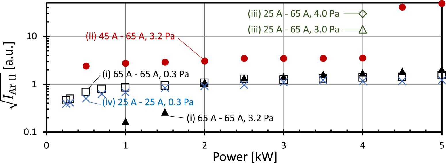
Figure 5. Power dependence of $\sqrt {I_{\rm {ArII}}}$ , which is proportional to $n_{{e}}$
 if $T_{{e}}$
 is constant; (i) 3.2 Pa, black closed triangles, (i) 0.3 Pa, black open squares, (ii) 3.2 Pa, red closed circles, (iii) 4.0 Pa, green open diamonds, (iii) 3.0 Pa, green open triangles, (iv) 0.3 Pa, blue crosses.

Figure 6. Power dependence of electron density measured by the microwave interferometer in the case of 45 A-65 A (3.2 Pa). The plasma diameter was assumed to be 10 cm.
3.2. Discussion
When the magnetic field in front of the antenna was relatively weak, a transition to helicon mode in argon plasma was observed. The HP dispersion relation under the assumption of the fundamental radial mode with the azimuthal mode number $m=0$ and homogeneous plasma is shown below (Shinohara Reference Shinohara2023)


Here, $\omega _{{0}}$ , $B_{{0}}$
 , $k_{{\parallel }}$
 , $k_{\perp 1}$
 , $\mu _{{0}}$
 and $e$
 denote the angular frequency, external magnetic field strength, wavenumber parallel to the external magnetic field, wavenumber perpendicular to the external magnetic field for the fundamental radial mode, permeability in vacuum and elementary charge, respectively. In (3.2) and (3.3), it is assumed that the boundary condition is insulating or conducting (Shinohara Reference Shinohara2018, Reference Shinohara2023).
According to (3.2) and (3.3), the $n_{{e}}$ value ranges from $4.4\times 10^{18}$
 to $6.6\times 10^{18}\ {\rm m}^{-3}$
 , when the $k_{\parallel }$
 value ranges from 21 to 31 $\rm {m}^{-1}$
 with $B_0 =32$
 mT at the diagnostics region based on case (ii) 45 A-65 A and a plasma radius of 3.71 cm. $k_{\parallel }$
 was assumed based on a parallel wavelength $\lambda _{\parallel } = 2{\rm \pi} /k_{\parallel }$
 from 20 to 30 cm, which is commonly observed in experiments (Shinohara Reference Shinohara2023), as well as in the experimental result for a similar set-up (Shinohara et al. Reference Shinohara, Motomura, Tanaka, Tanikawa and Shamrai2010, figure 5).
This $n_{{e}}$ value is consistent with the range considering the experimental result by a factor of 2.3 to 3.5. This error occurs because the experimental results are derived from averaged density, and the actual density may be considerably higher. Therefore, we consider that this experiment achieved the generation of high-density plasma by helicon waves. The error arises also because (3.2) assumes a uniform magnetic field and electron density. In the case of (I) 65 A-65 A, 3.2 Pa, $n_{{e}}$
 ranges from $4.5\times 10^{18}$
 to $6.8\times 10^{18}$
 m$^{-3}$
 with the same calculation ($B = 38$
 mT, $r = 4.06$
 cm), and there is a slight difference from the calculated dispersion relation in the case of (ii) 45 A-65 A. The difference may originate from the magnetic field strength and shape of the magnetic field line, which is suggested to be an essential factor for HP generation in non-uniform magnetic fields. The angle between the antenna and the magnetic field lines has been studied (Virko et al. Reference Virko, Shamrai, Virko and Kirichenko2004), but in the present configuration, this angle only varies within 1 $\%$
 .
.
Furthermore, the magnetic coil2 ($z=+21$ cm) appears to have a minimal effect on argon discharges, as inferred from a comparison between case (i) and case (iv). For further investigation, Langmuir and magnetic (B-dot) probes should be introduced, especially to measure the axial density distribution and wavelength. In the future work, we aim to optimize the magnetic field configuration for the effective operation of the pilot GAMMA PDX-SC. Considering that we have confirmed the importance of the magnetic field strength near the antenna, the HP source may be directly installed, even in the pilot GAMMA PDX-SC, which has a stronger magnetic field of up to 1.5 T. We expect the electron density and wavelength to be of approximately the same order around the antenna because the plasma source will be set at the point at which the magnetic field is of approximately the same order. However, it becomes a strong convergent magnetic field, and the plasma parameters along the $z$
 -axis may experience a large change.
4. Conclusion
The effect of the magnetic field strength on the argon plasma performance using a two-turn flat loop antenna was investigated. Argon HP generation was observed for the first time in the CTP device in the discharge experiment with varying magnetic field strength. The dispersion relation was calculated assuming a parallel wavelength of 20 to 30 cm, and the $n_{{e}}$ value was in agreement with the experimental result by a factor of 2.3 to 3.5. In addition, the magnetic field structure near the antenna exerted a significant effect. Development of Langmuir and magnetic probes that can directly measure the $n_{{e}}$
 , $T_{{e}}$
 and RF magnetic field structures are underway to advance the plasma generation process. This plasma source was developed for the pilot GAMMA PDX-SC with the challenging aim of achieving high-density, large-diameter plasma generation as well as to clarify the HP generation process using a flat loop antenna.
Acknowledgements
The authors thank Professor M. Ichimura and Professor Y. Nakashima for valuable discussions.
Editor Cary Forest thanks the referees for their advice in evaluating this article.
Declaration of interest
The authors report no conflict of interest.
Funding
This work was performed with the support and under the auspices of the NIFS Collaboration Research program (NIFS20KUGM148, NIFS20KUGM150, and NIFS23KUGM174). This work was supported by JST, the establishment of university fellowships towards the creation of science technology innovation (Grant Number JPMJFS2106).
Data availability statement
The data that support the findings of this study are available from the corresponding author upon reasonable request.
Author contributions
T.S. designed the concept of the experiment. T.S., N.E., R.M., M.H. and J.K. conducted all experiments and took the data. S.S. and T.F. contributed to the discussion of the collisional radiative model. All authors contributed equally to analysing data and reaching conclusions. The manuscript was written by T.S. and edited by S.S., N.E., J.K., S.T., T.F.


