1. INTRODUCTION
During the search for MH370 information derived from the analysis of satellite signals was released over a period of weeks as the investigation progressed. In some cases this information may have appeared confusing or contradictory, however in a situation where time is critical the early release of preliminary results followed by more detailed refinements is generally more useful than waiting for the completion of a comprehensive analysis. Satellite navigation systems rely on multiple satellites which are designed for accurate navigation and positioning: in this case only a few data points from a single communication satellite were available and an approximate track and final position were determined using techniques developed after the loss of the aircraft. This paper aims to shed some light on the way the analysis progressed over time, narrowing down the target search area at each iteration.
2. SATELLITE SYSTEM OVERVIEW
MH370, a Boeing 777-200ER aircraft registration 9M-MRO, was equipped with a satellite communications terminal that used the Inmarsat Classic Aero system. This system has been operational since 1990 and provides voice and data services to both cockpit and cabin through a network of seven geostationary satellites. Each satellite communicates with aircraft terminals, or Aircraft Earth Stations (AESs), through a single ‘global coverage’ beam, which links to a Ground Earth Station (GES) where calls are connected to their destination. Because the Classic Aero system uses a global beam it is not necessary for the aircraft to report its position to the GES for the system to work: in contrast aircraft using Inmarsat's SwiftBroadband system use a number of smaller spot beams, and have to report their location regularly to allow the network to use the appropriate beam.
Each aircraft terminal must logon to the network before calls can be made or received; this tells the network which satellite the aircraft is connected to, allowing calls to be routed appropriately. Once logged on the terminal monitors a signalling channel that is used to alert it to incoming calls and messages. If a terminal does not send any data for an hour the network checks that it is still connected by sending it a ‘Log-on Interrogation’ (LOI) message asking for a response. If no response is received the network will assume that the terminal has been switched off, and remove it from its list of active terminals. This one hour timer has since been reduced to 15 minutes.
After contact with MH370 was lost at 17:22 UTC, its satellite terminal continued to exchange signalling messages with the GES and it is these messages that were analysed to determine the likely location of the aircraft. Two key parameters associated with these messages were used in the analysis: the Burst Timing Offset (BTO) and the Burst Frequency Offset (BFO).
The aircraft satellite communication system operates at L Band, transmitting signals to the satellite at 1·6 GHz and receiving signals from the satellite at 1·5 GHz. The GES to satellite link uses C Band, transmitting at 6 GHz and receiving at 4 GHz. Several channels are used within these bands for message transmissions. One of the channels is called the P-Channel, which the aircraft continually listens to and is used for signalling and data transmissions from the ground to the aircraft. The R-Channel is used for signalling and short data transmissions from the aircraft to the ground.
For system efficiency and for the satellite communication to remain reliable, aircraft R-Channel transmissions are in time slots referenced to the P-Channel as received by the aircraft using the slotted aloha protocol. The BTO is a measure of how long from the start of that time slot the transmission is received. This is essentially the delay between when the transmission was expected (given a nominal position of the aircraft) and when it actually arrives, and is a measure of twice the distance of the aircraft from the satellite. This is illustrated in Figure 1. The BTO was only a relatively recent addition to the ground stations' data set, being added following the Air France 447 accident in 2009 to assist in geo-locating an aircraft.

Figure 1. Burst Time Offset Principle.
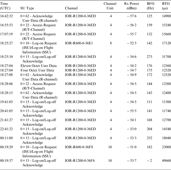
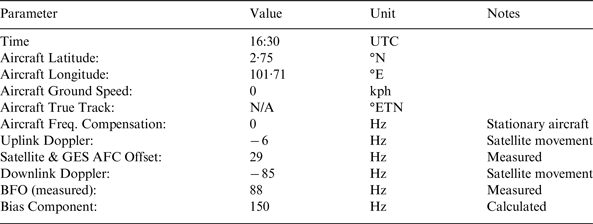
There is a limit to the number of aircraft that are able to share a single frequency, and so the Classic Aero system uses several different frequencies to carry traffic. The spacing between these frequencies is determined by the data rate plus an allowance for frequency errors due to aircraft oscillator and other tolerances. The BFO is the recorded value of the difference between the received signal frequency and the nominal frequency at the GES. It is determined by several factors including the aircraft's location and ground velocity, providing us with additional information in our search for MH370. This is further explained in Section 4. Table 1 presents these measurements for the MH370 flight.
Table 1. Signalling Message Parameters from Flight MH370 (Malaysian Government, 2014).

3. ARCS AND PROBABLE TRACKS
The first deduction that can be made from the signalling data is that the aircraft remained operational for at least seven hours after the loss of contact, as the satellite terminal continued to transmit messages during this period. It may further be deduced that the aircraft navigation system was operational, since the terminal needs information on location and track to keep its antenna pointing towards the satellite. Finally the varying BTO measurements indicate that the aircraft was moving (at speed) during this period. The terminal did not respond to the LOI message at 01:16 UTC on 8 March.
3.1. Initial BTO Analysis
The initial analysis related BTO measurement to the elevation angle from the aircraft to the satellite, based on work performed following the Air France 447 investigation. This achieved an approximate elevation angle accuracy of 1°, and showed the aircraft to lie close to the 40° elevation angle contour at 00:11 UTC (Figure 2). BTO measurements at 18:25 and 00:19 were excluded from the initial analysis as they gave anomalous results: these anomalies were subsequently resolved and will be covered later in this paper

Figure 2. Initial BTO Analysis (00:11 UTC Arc Highlighted).
.
3.2. Refined BTO Analysis
While the initial BTO analysis provided a rapid and reasonably accurate assessment of the aircraft location at specific measurement times it made the approximation that the satellite was at its nominal orbital location above the equator. In fact the satellite orbit is slightly inclined, resulting in a north-south movement of 2,412 km each day. To correct for this a more precise analysis was performed taking account of the actual location of the satellite at each measurement point.
The BTO measurement comprises two components: a bias component caused by fixed delays in the system, plus a variable component caused by the time taken for the outbound radio wave to pass from the GES to the aircraft and the inbound radio wave to make the return journey. This allows a simple equation to be developed relating satellite to aircraft distance to timing delay.
where bias is a fixed (and constant) delay due to GES and AES processing and c is the speed of light.
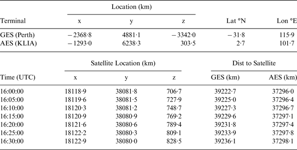
To determine the bias value, and obtain an indication of the accuracy of the technique, signals exchanged between the GES and aircraft in the 30 minutes prior to take off were processed. During this 30 minute period the satellite moved 122 km. Table 2 shows the location of the satellite, aircraft and GES over this period, expressed in an Earth Centred Earth Fixed (ECEF) coordinate system where the centre of the earth is the origin, the z-axis is due North and the x and y axes are in the equatorial plane with 0° and 90° longitude respectively (note: throughout this paper we use an ellipsoid Earth model).
Table 2. BTO Calibration Geometry.

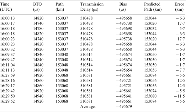
Seventeen measurements were taken during this 30 minute period, and these were processed to estimate the fixed timing bias. The mean bias of −495,679 μs was then used to predict the path length from the measured data (Table 3 right hand columns), showing a high degree of consistency. The peak error out of all 17 measurements is 17·7 km in the distance from GES to AES and back, equivalent to less than 9 km in the distance between the satellite and the AES.
Table 3. BTO Calibration (Kuala Lumpur International Airport).

With the bias value determined from the ground measurements, the in-flight measurements were processed to determine the satellite to aircraft distance at each measurement point. The locus of points on the earth of constant distance to the satellite is a ring (for a spherical earth these would be circles) centred on the sub-satellite point. These results were then converted to a set of rings at an assumed cruising altitude of 10,000 m, where the distance from the satellite matched the measurement. The rings were then reduced to arcs by excluding locations that were too far away from the original location for the aircraft to reach at its highest speed. Figure 3 shows the first three arcs produced by this technique, with the true aircraft location (as reported by the Mode S transponder) overlaid, illustrating the accuracy achieved.

Figure 3. 16:42, 16:56 and 17:07 Arcs with Mode S Positions Shown.
3.3. Log-on Sequence BTO Measurements
The BTO readings for the signals at 18:25:27 and 00:19:37 UTC are much larger than the other readings, and were not included in the original analysis. However the final signal has special significance as it appears to have been triggered by the aircraft terminal being power cycled, and may indicate the aircraft running out of fuel. The signals at 18:25:27 and 00:19:37 were both generated as part of a logon sequence, contrasting with the other messages which were generated as part of a standard LOI exchange. Each power up sequence starts with a Logon Request message that has been found to have a fixed offset of 4600 μs relative to the LOI message exchange by inspecting historical data for this aircraft terminal. The subsequent messages during the logon sequence were found to have unreliable delay and are believed to be an artefact of the terminal switching channel and frequency during logon and so are not used in this analysis. This means that the BTO data for 18:25:34 and 00:19:37 should be ignored, but that corrected BTO values of 12520 and 18400 μs may be derived from the Logon Request messages at 18:25:27 and 00:19:29 UTC respectively. This results in the rings shown in Figure 4 for the later stages of the flight.

Figure 4. BTO Rings during Later Stages of Flight (ATSB, 2014).
3.4. Initial Flight Path Reconstruction
The BTO analysis provides us with a series of arcs that the aircraft must cross at specific times. Combining this with the last known location and the viable aircraft speeds allows us to identify a number of flight paths. Each path must cross the arcs at the appropriate time, and it must be possible to travel from one arc crossing point to the next in the available time as illustrated in Figure 5. However we do not know the track or speed of the aircraft, nor whether these are going to change with time, which results in a large number of potential flight paths. While the aircraft could have flown in a relatively straight line travelling as far north as Kazakhstan or deep into the southern Indian Ocean, it could also have flown around in circles and ended up almost anywhere on the final arc.

Figure 5. Flight Path Reconstruction Technique.
Initial flight path reconstruction attempts were based on the aircraft flying at a steady speed on a relatively constant track consistent with an aircraft operating without human control. It was initially thought that for the fuel to have lasted until 00:19 UTC the aircraft would have needed to be flying at high altitude, where the air is thinner and drag is reduced, which would have resulted in its flying at close to its maximum speed of just over 500 knots (926 kph). This gave two solutions, one in a northerly and the other in a southerly direction, as illustrated in Figure 6, where the red lines indicate the flight paths prior to 00:19 UTC and the green lines indicate the potential additional flight paths between the last signal at 00:19 UTC and the failure to respond to the LOI message sent by the GES at 01:15 UTC.

Figure 6. Initial Flight Path Reconstructions.
It is important to remember that these initial flight paths, while consistent with the BTO timing data and the aircraft performance, were based on a number of assumptions: that the aircraft travelled at a steady and high speed and did not make any manoeuvres beyond a turn to the north or south shortly after its last radar detection.
4. FREQUENCY CALCULATION
While the timing work derived a series of high-resolution location arcs, these gave many different flight path solutions resulting in an extremely large search area. Even discriminating between southern and northern routes was impossible, although the northern route appeared less likely given the large number of civil and military radar installations it passed over. The possibility also remained of a circular flight path ending in China, Vietnam, Borneo or Indonesia. To try and resolve this ambiguity an analysis of the BFO data was undertaken, in the hope that the Doppler components of the two routes would be sufficiently different to discriminate between them.
4.1. Theory
Unlike the timing calculation, which predicts the location of the aircraft relative to the satellite from the BTO measurement, the frequency calculation works backwards, taking the aircraft location and velocity at a given time and calculating the BFO that this would generate. This enables the likelihood of potential flight paths to be evaluated, depending on how well the calculated BFO values align with the measured values during the flight.
The BFO may be calculated by combining the contributions of several factors illustrated in Figure 7:
where ΔF up is the Doppler on the signal passing from the aircraft to the satellite, ΔF down is the Doppler on the signal passing from the satellite to the GES, δf comp is the frequency compensation applied by the aircraft, δf sat is the variation in satellite translation frequency, δf AFC is the frequency compensation applied by the GES receive chain and δf bias is a fixed offset due to errors in the aircraft and satellite oscillators.

Figure 7. Basis of Frequency Calculation.
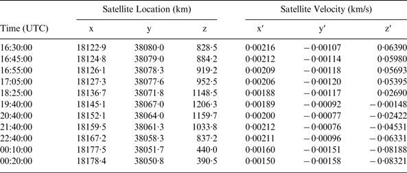
The uplink and downlink Doppler may be calculated from the relative movement of the aircraft, satellite and GES using the signal frequencies of 1646·6525 MHz (uplink) and 3615·1525 MHz (downlink). The satellite location and velocity are accurately determined by Inmarsat for satellite station keeping and collision avoidance activities, and are shown in Table 4 for the key times used in the analysis. For the purpose of illustration Figure 8 shows the locus of the sub-satellite point (the point on the earth's surface directly below the satellite) highlighting the location at key times during the MH370 flight.

Figure 8. 3F1 Sub-Satellite Point Locations during MH370 Flight.
Table 4. Satellite Location and Velocity (ECEF).

The aircraft terminal adjusts its transmit frequency to compensate for the Doppler induced on the uplink signals by the aircraft velocity. Aircraft latitude, longitude, track and ground speed are used to calculate the Doppler shift the signal would experience if the satellite was at its nominal location over the equator. This only partially compensates for the Doppler associated with the aircraft's velocity as it does not allow for vertical movement (which introduces discrepancies when the aircraft is climbing/descending) and the satellite is rarely at its nominal location: these small errors are immaterial to the communications performance, but do affect the BFO. This is δf comp in Equation (2).
Signals received by the satellite are translated in frequency, amplified and relayed to the GES. The satellite translation frequency is derived from an oscillator that is maintained in a temperature-controlled enclosure to improve its stability. During eclipse periods when the satellite passes through the earth's shadow, the satellite temperature drops resulting in a small variation in translation frequency. Such an eclipse occurred during the flight of MH370 starting at 19:19 UTC and ending at 20:26 UTC, affecting the 19:40 and 20:40 measurements. The temperature of the oscillator is also affected by the rotation of the satellite relative to the sun every 24 hours which gives a regular daily temperature variation to the equipment, further complicated by heaters which are switched on if the equipment drops out of pre-defined temperature limits. All of these thermal effects impact on the satellite translation frequency. This is δf sat in Equation (2).
The GES translates the frequencies it receives from the satellite to an Intermediate Frequency (IF) before passing them to the equipment that demodulates and processes them. The translation frequency applied is controlled by an Automatic Frequency Control (AFC) loop to compensate for the downlink Doppler. The AFC loop works by monitoring the absolute frequency of a reference signal transmitted through the satellite, and using these measurements to determine the appropriate translation frequency to apply over a 24-hour period. For operational reasons associated with the hardware used to implement this AFC loop in the Perth GES it only partially compensates for the downlink Doppler. This is δf AFC in Equation (2).
The final component in the frequency calculation is a fixed bias component related to the aircraft and satellite oscillator errors such as those associated with long term drift and ageing. While manufactured to high tolerances, the oscillators on the aircraft and the satellite exhibit small fixed frequency errors that result in a bias value appearing in the BFO associated with any particular terminal. As the value is constant it can be determined through calibration measurements when the aircraft location and velocity are known. This is δf bias in Equation (2). Table 5 shows how the frequency bias for flight MH370 was determined, based on measurements taken prior to take off.
Table 5. Frequency Bias Calibration.

4.2. Initial Results
Applying the BFO calculation to the original northern and southern routes produced the curves shown in Figure 9, which were published by the Malaysian authorities on 25 March 2014 and used to justify the southern route and the loss of the aircraft. It is noted that the discrepancies in the early measurements were (correctly) ascribed to the effect of the aircraft climbing. The spike in the measured data at 18:28 is not fully understood and was originally ascribed to a possible manoeuvre of the aircraft: although it could be related to frequency changes during the logon sequence described in Section 3.3.

Figure 9. Initial BFO Results indicating Southern Route.
While not providing an exact match, the measured BFO data much more closely resembled the southern route after 18:30 UTC, indicating that the aircraft was most likely to have been travelling in a southerly direction. This information was double checked, validated against flights made by other aircraft and reported to the authorities to assist in the on-going search. Work then continued on identifying a southern route that better matched both timing arcs and BFO curve and on refining the BFO model which (at this stage) did not include second order effects associated with satellite eclipse or accurate measurements of the GES frequency compensation loop.
5. REFINED FREQUENCY CALCULATION
Following the initial work considerable effort went into refining the BFO model and characterising the various components within it. At the same time improvements were made in the understanding of the measurement data and identifying which points were reliable and which were not.
5.1. GES AFC Compensation
The Perth GES partially compensates for C Band Doppler effects by adjusting the translation frequency it applies to receive signals. This frequency adjustment is controlled by an AFC receiver, which measures the absolute downlink frequency of a constant uplink frequency (Pilot) signal that is transmitted to the satellite from Inmarsat's Burum facility in the Netherlands. The receiver maintains a moving average of the received frequency over 24 hours and treats the difference between the received frequency and this average as being due to Doppler. Based on knowledge of the Pilot transmitter location and frequency and the GES location it determines the component of this Doppler attributable to the C Band downlink and adjusts the receive translation frequency to correct for this.
The AFC receiver was not designed to handle a GES located south of the equator, and so to make it work it was configured with a positive GES latitude rather than a negative one. This means that the receiver did not behave as intended, and that its Doppler compensation algorithm did not accurately remove the C Band component of Doppler present in the signal. Fortunately Inmarsat monitors the received frequency of the Pilot signal after it has passed through the frequency conversion at the GES and it is possible to calculate the frequency conversion applied by the receive chain so that it can be calibrated out in the BFO calculation.
Figure 10 shows the calculated Doppler induced frequency shift on the Pilot signal for 7 March 2014. The L Band uplink component is smaller than the C Band downlink component as Doppler shift is proportional to signal frequency. It is interesting to note that when the C Band value is positive the L Band value is negative, as the Pilot is transmitted from north and received from south of the equator, so when the satellite is moving towards the GES it is moving away from the Pilot transmitter.

Figure 10. Calculated Pilot Frequency Doppler Offset.
After AFC controlled frequency conversion the Pilot frequency should lose the Doppler variation attributable to the C Band downlink, but retain the contribution due to the L Band uplink. That is to say the output signal should exhibit a 24 hour frequency variation of ±52 Hz with the highest frequency occurring at around 14:00 UTC. However the output frequency actually exhibits a 24 hour variation of±20 Hz, with the lowest frequency occurring around 14:00. It also shows a distinct kink between 19:30 and 22:30, as illustrated in Figure 11.

Figure 11. Measured Pilot Frequency Error (After Conversion).
This difference in the measured frequency can be explained by the fact that the AFC receiver expects the L Band and C Band Doppler components to add, and so interprets the ±60 Hz input signal variation as being due to the sum, rather than the difference, of the L and C Band components and so removes two thirds of the variation which would be the C Band contribution in such a case.
5.2. Satellite Thermal Modelling
The kink in the measured Pilot frequency characteristic was unexplained until it was noticed that it coincided with the satellite eclipse which took place between 19:19 and 20:26 UTC, and so was probably due to satellite oscillator errors due to thermal variations caused by the eclipse. However if we see such marked variations in translation frequency during the satellite eclipse period, it is likely that we will see smaller level variations due to thermal cycling of the satellite oscillator throughout the day that would reduce the accuracy of the BFO calculation.
By modelling the performance of the AFC receiver over several days it is possible to deduce the input signal frequency that it receives and compare the frequency variations of this reconstructed signal with the calculated Doppler to determine the frequency variations due to the satellite oscillator. These are shown in Figure 12 for the day of the MH370 flight, and align well with the temperature of the oscillator that is monitored through routine satellite telemetry (see Figure 13).

Figure 12. Satellite Translation Frequency Variation.

Figure 13. Satellite Oscillator External Temperature Variation.
While the agreement between satellite thermal effects and residual Pilot frequency error demonstrates the physical source of the variation, it is not necessary to separate the AFC and satellite effects when performing the BFO calculation as their combined effect is directly determined by subtracting the output signal frequency variation shown in Figure 11 with the signal frequency variation due to Doppler shown in Figure 10.
5.3. Refinement of BFO Samples
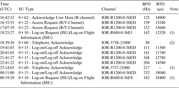
Detailed analysis of BFO samples taken from other flights showed a high degree of consistency for the signalling message frequencies, with the exception of those that were performed immediately after the initial logon process. This called into question the BFO measurements after the log-on sequences at 18:25 and 00:19. However it was also determined (by the same method) that the first message transmitted by the aircraft in the logon sequence, the Logon Request message, did provide a consistent and accurate BFO measurement. This means that we can use the Logon Request message information from 18:25:27 and 00:19:29, but it is prudent to discount the measurements between 18:25:34 and 18:28:15 inclusive, and the one at 00:19:37.
In addition to the LOI related signals presented in Table 1, MH370 also exchanged signalling messages with the Perth GES at 18:40 and 23:14 UTC related to unanswered ground to air telephone calls. The signalling associated with these calls does not result in a BTO measurement, but did give BFO measurements of 88 and 217 Hz respectively which may be used. This results in a refined set of BTO/BFO measurement data presented in Table 6 for the flight path reconstruction work.
Table 6. Refined Signalling Message Parameters from Flight MH370.

(1) Modified value, determined by subtracting 4600 μs from measured
(2) Average of 51 values ranging from 86 to 90 Hz. No BTO value available for voice channels
(3) Average of 29 values ranging from 216 to 222 Hz. No BTO value available for voice channels
The fit to the originally postulated northern and southern paths is illustrated in Figure 14 that fits the northern path until 18:25, but switches to the southern path by 18:40. The divergence between the measured data and the southern path suggest that a better match may be possible if we make some minor adjustments to the flight path.

Figure 14. BFO Results using Refined Model.
5.4. Validation of BFO Equation
The technique was validated by applying it to measurements taken from other aircraft whose location and velocity were known, and was found to work well. Validation was performed against several aircraft that were in flight at the same time as MH370, and for the MH370 aircraft in the days leading up to the accident, and good agreement between predicted and measured BFO was seen. Figure 15 shows the measured BFO for flight MH21 that travelled from Kuala Lumpur to Amsterdam at the same time as the MH370's final flight, overlaid with the upper and lower BFO predictions (±7 Hz) using the refined BFO model. This suggests that ±7Hz is a conservative estimate of the typical accuracy BFO calculation achieves, as well as illustrating the BFO versus time characteristics for a flight moving along a path close to the Northern route. While the validation demonstrates the general accuracy of the BFO technique, it is important to note that agreement is only achieved with ±7 Hz accuracy during this flight, and to assume better accuracy for the measurements taken on MH370 would be unrealistic.

Figure 15. Burst Frequency Offset Validation (Amsterdam Flight).
5.5. BFO Calculation Sensitivity
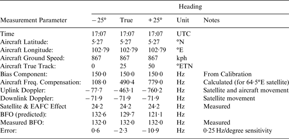
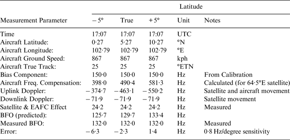
Tables 7 and 8 present the BFO calculation during the early phase of flight MH370 when the aircraft location, ground speed and track are known. They illustrate the sensitivity of the BFO frequency calculation to track and latitude errors, showing that the calculation works and that it is reasonably sensitive to errors in aircraft location and track.
Table 7. BFO Sensitivity to Aircraft Track Errors.

Table 8. BFO Sensitivity to Aircraft Latitude Errors.

Combining the sensitivity data with the measurement accuracy of ±7 Hz indicates that inaccuracy in each individual BFO measurement would correspond to ±28° heading uncertainty and ±9° of latitude uncertainty.
6. HYPOTHETICAL FLIGHT PATH RECONSTRUCTION
Many techniques may be used to generate an aircraft flight path consistent with the BTO and BFO measurements, bounded by the physical capabilities of the aircraft and its assumed operating mode. Several different agencies worked on this issue in parallel, both independently and collaboratively. What we present here is a simplified flight path reconstruction technique to illustrate how the measurements may be transformed into a reasonable flight path. It should be emphasised that other members of the international investigation team developed far more sophisticated models factoring in aircraft and avionics performance characteristics to determine the final underwater search area.
6.1. Early Flight Path
The last published primary radar location of the aircraft was at 18:22 UTC when it passed close to the MEKAR waypoint at N06 30, E096 30. Five minutes later it crossed the 18:27 arc generating a BFO of 142 Hz. Due to the close proximity of the arc crossing to the last radar fix we have limited uncertainty in the arc crossing points and so the main variables we have to align the predicted BFO with the measured value are the aircraft ground speed and track. Trial and error shows that we obtain the best BFO match for an aircraft track of 300°, which is consistent with the aircraft travelling along airway N571 towards the IGOGU waypoint at N07 31, E094 25 at a ground speed of 480 knots. Such a flight path would be consistent with the route determined by radar prior to 18:22 UTC where the aircraft appears to be moving between waypoints.
6.2. Late Flight Path
The technique presented here to reconstruct the end of the flight path uses a constant ground speed model. Constant ground speed is capable of being programmed into an autopilot, and flight paths consistent with these are relatively straightforward to generate and evaluate.
At some time between 18:27 and 19:41 MH370 turned south, however rather than trying to predict when (and where) the aircraft turned this analysis takes the 19:41 arc as its starting point. It models a large number of routes that started on the 19:41 arc between 6°N and 4°S, travelled at ground speeds ranging from 375 to 500 knots and crossed the timing arcs at the appropriate times. The track of each route was allowed to change as it crossed each arc, with the mean of the approach and departure tracks being used to calculate the BFO. Each route was analysed and the error between predicted and measured BFO evaluated to identify the route with the best match.
The ±7 Hz tolerance between measured and predicted BFO (see Figure 15) results in many candidate routes meeting the BFO constraints, giving a probability distribution of locations for the 00:19 arc crossing. The BFO predictions for one example route are plotted in Figure 16 between the upper and lower BFO measurement bounds. This route crossed the 19:41 arc at 0°N and travelled south at a constant ground speed of 450 knots, matching the BFO measurements to within 2 Hz at each of the five signalling data points between 19:41 and 00:11 UTC and within 6 Hz of the two voice call data points at 18:39 and 23:14. While the route is no more valid than many other potential routes it is interesting as it gives a good match to the measured data at a relatively constant track and ground speed.

Figure 16. BFO Results for Example Flight Path.
6.3. Consolidated Flight Path
It is possible to join the early and late flight paths of the previous two sections to generate a hypothetical route that is consistent with the measured data, by assuming that MH370 flew from the last primary radar fix to the IGOGU air waypoint from where it turned south towards the ISBIX waypoint (N00 22, E093 40·5) and then continued in a southerly direction with its true track drifting from the initial 186° (IGOGU to ISBIX) to 180° by the end of the flight.
Table 9 presents the results of the BFO calculation for the reconstructed flight path, breaking out the different contributors to the frequency offset. The uplink Doppler contribution (ΔF up) is split into two components: aircraft velocity in the direction of the satellite and satellite velocity in the direction of the aircraft. The errors at 16:42, 16:55 and 00:19 are thought to be due to vertical movement of the aircraft that is not included in this model. The values at 18:39 and 23:14 are based on the telephone call attempts, where BFO is recorded but BTO is not: the values in the table are the average of all the measurements associated with the call attempts, which spanned from 86 to 90 Hz at 18:39 and from 216 to 222 Hz at 23:14. Figure 17 illustrates the route.

Figure 17. Example Flight Path.
Table 9. Example Reconstructed Flight Path Results.

7. CONCLUSIONS
The analysis presented in this paper indicates that MH370 changed course shortly after it passed the Northern tip of Sumatra and travelled in a southerly direction until it ran out of fuel in the southern Indian Ocean west of Australia. A potential flight path has been reconstructed that is consistent with the satellite data, indicating a last contact location of 34·7°S and 93·0°E, but it is stressed that the sensitivity of the reconstructed flight path to frequency errors is such that there remains significant uncertainty in the final location.
ACKNOWLEDGEMENTS
This material is based on work performed by Inmarsat in its role as Technical Advisor to the UK Air Accidents Investigation Branch (AAIB). We would like to thank our colleagues in the wider Flight Path Reconstruction group including Thales, the US National Transportation Safety Board (NTSB), Boeing and Australia's Defence Science and Technology Organisation (DSTO), who all independently verified and calibrated the frequency model, Thales and Honeywell who provided expert knowledge on the AES terminal performance, and SED and Square Peg Communications who provided expert knowledge on the GES equipment. The group has been expertly led by the Australian Transport Safety Bureau (ATSB) along with Malaysia's Department of Civil Aviation (DCA).
Inmarsat and the Flight Path Reconstruction group are committed in their continued support in the search for MH370 to help find closure for the families involved.


