1. INTRODUCTION
Pedestrian navigation based on Micro-Electro-Mechanical Systems (MEMS) inertial sensors has been emerging in the inertial technology field in recent years (Abdulrahim et al., Reference Abdulrahim, Hide, Moore and Hill2012; Jiménez et al., Reference Jiménez, Seco, Zampella, Prieto and Guevara2011; Reference Jiménez, Granja, Prieto Honorato and Guevara Rosas2012). Pedestrian navigation and positioning systems based on body-worn Inertial Measurement Units (IMU) fall into two main categories; foot-mounted systems and waist-worn systems (Lan and Shih, Reference Lan and Shih2012). Step detection accuracy is the basis of the two positioning systems above and it can directly affect the ultimate positioning accuracy. In a foot-mounted pedestrian inertial navigation system, flat zone detection can commonly detect steps through zero velocity information generated by the foot (Jiménez et al., Reference Jiménez, Seco, Prieto and Guevara2010; Abdulrahim et al., Reference Abdulrahim, Hide, Moore and Hill2011). The error rate for this method has proved to be as low as 0·1% (Jiménez et al., Reference Jiménez, Seco, Prieto and Guevara2009). However, a waist-worn pedestrian inertial navigation system is more convenient and comfortable for users. However, the flat zone detection method is not suitable for detecting steps with the sensors positioned in this way (Shin et al., Reference Shin, Lee and Park2010). In a waist-worn pedestrian inertial navigation system, the peak detection method and the zero-crossing detection method (Kappi et al., Reference Kappi, Syrjarinne and Saarinen2001; Lepakoski et al., Reference Leppakoski, Kappi, Syrjarinne and Takala2002; Shin et al., Reference Shin, Park, Kim and Lee2007) are mainly applied to detect steps and the former is more widely used (Tumkur and Subbiah, Reference Tumkur and Subbiah2012; Schindhelm, Reference Schindhelm2012; Susi et al., Reference Susi, Renaudin and Lachpelle2013).
Many researchers have studied the peak detection method. The vertical acceleration peak is detected by a sliding window with fixed length and some constraints determine its presence in detecting steps (Levi and Judd, Reference Levi and Judd1996). Vertical acceleration signals are also smoothed by wavelet transformation; then the peak signal is identified by a fixed length window (Sun et al., Reference Sun, Mao, Tian and Zhang2009; Gusenbauer et al., Reference Gusenbauer, Isert and Krösche2010). Additionally, to improve the robustness for complex motion, a fixed length window detects steps by combining forward acceleration peak signals with vertical acceleration peak signals (Lee and Mase, Reference Lee and Mase2001). Some researchers have demonstrated that peak signals of roll angle can detect steps; a low-pass filter can process most multiple peak signals in the course of an ordinary stride (Jirawimut et al., Reference Jirawimut, Ptasinski, Garaj, Cecelja and Balachandran2001). But some multiple peak signals cannot be filtered because of the frequency of vibration. Also, waist shaking interference signals are very close to the frequency of signals during walking (Sun et al., Reference Sun, Mao, Tian and Zhang2009). Recently, an adaptive threshold algorithm has been proposed and used to determine peaks for detecting steps (Ryu et al., Reference Ryu, Ahn, Kim, Kim, Kim, Woo and Chang2013).
In actual walking, the motion law of the waist hip bone is complex. For a waist-worn pedestrian inertial navigation system, a waist-worn accelerometer measuring vertical acceleration will produce false peak signals under interference from vibration and waist shaking (Ladetto, Reference Ladetto2000). This interference reduces the accuracy of step detection and position (Cho and Park, Reference Cho and Park2006). To solve this problem, this work analyses the relationship between periodic acceleration at the pedestrian's centre of gravity and walking stance during walking. Then an adaptive dual-window step detection method is proposed. A dual-window detects peak signals of vertical acceleration and the window length is adjusted based on the change in step frequency, namely, the steps walked in one second. This method is able to reduce step detection errors resulting from vibration and waist shaking. More importantly, steps can still be accurately detected with changing step frequency. On this basis, this method can effectively improve the positioning accuracy.
2. PERIODIC ACCELERATION OF PEDESTRIAN CENTRE OF GRAVITY
While walking, a pedestrian's centre of gravity experiences a periodic (approximately sinusoidal) change in vertical acceleration, which corresponds to the pedestrian's continuously changing stance. Regardless of the interference from vibration and waist shaking, the walking stance has the approximate relationship with the vertical acceleration at the body centre of gravity as shown in Figure 1. T is the time interval over one step.

Figure 1. The approximate relationship between vertical acceleration and walking stance.
Figure 1 shows that when the distance between two feet is the greatest, the vertical acceleration reaches the crest peak (the maximum peak in one step) and body centre of gravity is at the lowest position. As the pedestrian continues to step forward, vertical acceleration begins to decrease; the position of the body centre of gravity moves up. When the body centre of gravity reaches the highest position, vertical acceleration reaches the valley peak (the minimum peak in the step). Then the body centre of gravity sequentially moves from the highest position to the lowest position with changing walking stance. Meanwhile, the vertical acceleration begins to increase until the pedestrian walks one step forward.
From the above analysis and Figure 1, vertical acceleration correspondingly appears as one crest peak and one valley peak in the time interval T while walking one step. Therefore times of crest peak and valley peak in vertical acceleration can be applied to detect steps.
3. ADAPTIVE DUAL-WINDOW STEP DETECTION METHOD
The IMU is positioned at the waist back because this position is close to the body centre of gravity. The Z-axis accelerometer measures the vertical acceleration. az is the specific force signal measured by the Z-axis accelerometer and it is composed of the component of gravitational acceleration and motion acceleration. The vibration from the impact between feet and ground and waist shaking during the actual walking is always present. These interferences result in false peaks as arrow marks shown in Figure 2. The circular marks are the peaks of signals az including crest peaks and valley peaks in every step.
Figure 2. The actual collected signals.
It is difficult to completely filter false peaks in signals az by signal processing methods. Hence the false peak will reduce step detection accuracy by the peak detection method. For this problem, this paper proposes an adaptive dual-window step detection method. The peak of signal az is detected by dual-windows and step frequency adjusts the window length. Then the false peak signals can be rejected and thus improve step detection accuracy.
3.1. The Principle of Dual-Window Peak Detection
To restrain interference from vibration and waist shaking and effectively detect the peak of signals az including crest peak and valley peak, this paper proposes a method to detect the peak of signals az with two overlapping sliding windows. In this paper, the window is a single-dimensional array to extract the peak of the signals. Window length L is the array length and also the sampling number in one window.
The basic principle of dual-window peak detection method is shown in Figure 3. Two windows overlap only one signal sampling point; if the only overlapping signal sampling point is the maximum or minimum peak in the dual-window, then the overlapping sampling point is the corresponding crest or valley peak of signals az in one step.
Figure 3. Principle of dual-window peak detection.
In particular, the array X is the first window and the array Y is the second; the length of array X and Y is L. When the sample number is i, signal az(i) is processed through a low-pass filter to eliminate noise and the filtered signal is A(i). The array X and Y are determined through Equations (1).
 $$\hskip-4pt \left\{ \!\!{\matrix{ {X = [A(i - 2L + 2),A(i - 2L + 3),A(i - 2L + 4), \cdots, A(i - L),A(i - L + 1)]} \cr {\hskip-13pt Y = [A(i - L + 1),A(i - L + 2),A(i - L + 3), \cdots, A(i - 2),A(i - 1),A(i)]} \cr}} \right.$$
Equations (1) show that the length of the two windows is L and the only overlapping sampling point is A(i – L + 1). According to the principle of dual-window peak detection, if A(i – L + 1) is the maximum or minimum peak in the dual-window, A(i – L + 1) is the corresponding crest or valley peak of signals az in one step.
3.2. The Adaptive Adjustment Rules for Window Length
When a pedestrian walks at a different step frequency, step period T is changing, which is the time between two vertical acceleration peaks in the two adjacent steps. Under such circumstances a fixed length window (Levi and Judd, Reference Levi and Judd1996) will be prone to step detection errors. If the window is too short compared to the stepping period, signal peaks due to vibration and waist shaking may be erroneously detected as extra steps; if the window is too long, the method may fail to detect some real steps. Analogously, the loss of step detection accuracy may occur when the window length L is too long or short in the dual-window peak detection method proposed in this paper. So in the actual application, it is necessary to adjust the window length L on the basis of the measured step period. The window length L and step period T are chosen for detecting the peak accurately according to Equation (2), in which the symbol fs is the sampling frequency of system.
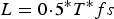 $$L = 0 \!\cdot\! 5{^\ast}T{^\ast}fs$$
In fact, the variation ΔT of step period T cannot change suddenly over a short period of time. Considering the practical small variation ΔT between two adjacent step periods, two overlapping windows are adopted. The window length L in the current T is determined by the last step period T according to Equation (2). The peak of vertical acceleration can only be obtained in the overlap of two windows. The window length L can be adaptively adjusted according to Equation (2) when the pedestrian walks with changing step frequency. The analysis of data collected from pedestrians walking with different speeds and stride lengths shows that step frequency is typically not greater than five steps per second. The step frequency (five steps per second) corresponds to the step period T = 0·2s. The first window length L of ordinary people can be determined as shown in Equation (3).
 $$L = 0 \!\cdot\! 1{^\ast}fs$$
For example, when the sampling frequency of system fs is 100 Hz, the first window length L is 10 according to Equation (3). Arrays X and Y corresponding to the two windows are determined as Equations (4).
 $$\left\{\!\!\! {\matrix{ {X = [A(i - 18),A(i - 17),A(i - 16), \cdots, A(i - 10),A(i - 9)]} \cr {Y = [A(i - 9),A(i - 8),A(i - 7), \cdots, A(i - 2),A(i - 1),A(i)]} \cr}} \right.$$
At the beginning, step period T can be set to 0·2 s for ordinary people and the first window length L is determined according to Equation (3). In the course of walking, the window length L can be adjusted based on corresponding step frequency. The step period T should be updated for adjusting window length L. According to the principle of dual-window peak detection, the method can detect the peak of signals az including crest peak and valley peak in every step. On this basis, the sample number j corresponding to the peak is obtained. The product of sample number j and sampling period of the system is the real time peak occurring. When the peak occurs at the sampling point A(i – L + 1), the corresponding sample number j is determined by Equation (5).
 $$j = i - L + 1$$
When the sample number is j, the period T_crest, T_valley of crest peak and valley peak is the time interval between the adjacent two crests or valley peaks. And T_crest(N1)/T_valley(N2) can be determined by Equations (6) and (7) respectively.
 $$\!\!\!\!\!\!\!\!\!\!\left\{ \!\!{\matrix{ {crest\_\!\_time(N1) = j} \cr {T\_\!\_crest(N1) = (crest\_\!\_time(N1) - crest\_\!\_time(N1 - 1)){^\ast}(1/{fs})} \cr}} \right.$$
 $$\left\{ {\matrix{ {valley\_\!\_time(N2) = j} \cr {T\_\!\_valley(N2) = (valley\_\!\_time(N2) - valley\_\!\_time(N2 - 1)){^\ast}(1/fs)} \cr}} \right.$$
Among them, crest_time(N1)/valley_time(N2) records the sample number j corresponding to the crest/valley peak. N1/N2 is the number of crest/valley peaks of signals az in Equations (6) and (7) that occurred. From Section 2, the step period T, T_crest and T_valley should be equivalent in theory. When one crest peak and one valley peak of vertical acceleration appear in succession, the pedestrian walks forward a step. The step period T can be determined by Equation (8).
 $$T(N) = 0 \!\cdot\! 5 \times (T\_\!\_crest(N1) + T\_\!\_valley(N2))$$
In Equation (8), N is a whole number of steps. The step period T is updated based on the step frequency for realising the online adjustment of window length L in real time. Thereby a dual-window whose length can be adaptively adjusted can detect the crest peak and valley peak of signals az. This will lay the foundation for the subsequent step detection method proposed.
3.3. Adaptive Dual-Window Step Detection Method
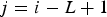
Based on the relationship between periodic acceleration of the pedestrian centre of gravity and walking stance in Section 2, a step should occur when one crest peak and one valley peak in vertical acceleration appear in succession. To improve the accuracy of step detection, we combine the crest peak and the valley peak to detect steps and adopt the dual-window peak detection method to implement it. Particularly, when it appears one time for the crest or valley peak of signals az, step number Step will be increased by 0·5 (or adding a half step). Therefore N is the largest integer less than or equal to Step. In this way, it can reduce the step detection error. The condition C = 1 denotes the appearance of crest or valley peak, and the condition C = 0 is contrary. Step(i) is the number of steps walked at the sample number i. Thus a step detection method is shown in Equations (9).
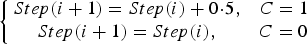 $$\left\{ {\matrix{ {Step(i + 1) = Step(i) + 0\! \cdot \!5,} & {C = 1} \cr {Step(i + 1) = Step(i),} & {C = 0} \cr}} \right.$$
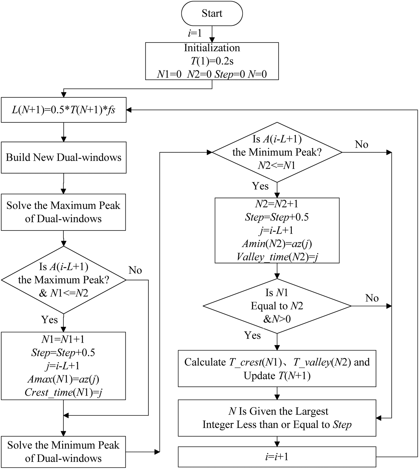
For detecting steps walked, firstly, the first window length L(1) is determined according to Equation (3). Then two arrays X and Y corresponding to the dual-window are created based on Equations (1). Equations (5)–(8) are used to update the step period T and the window length L is adjusted adaptively through Equation (2). Then the crest peak and valley peak of signals az in every step are detected by the dual-windows peak detection method. Finally, the actual steps are determined by Equations (9). The detailed algorithm flowchart is shown in Figure 4.
Figure 4. Flowchart of adaptive dual-window step detection algorithm.
In Figure 4, symbol i is the sequence of sampling points to control the running of the algorithm and the first step period T(1) is set as 0·2 s. Additionally, N1/N2 record the crest/valley peak number of signals az. The symbol ‘Step’ denotes the steps walked with half step and N denotes the integer steps walked. T(N) is the step period and L(N) is the window length when the step count is N. fs is the sampling frequency of system. The sample number corresponding to the crest/valley peak of vertical acceleration is recorded by the symbol j and stored in the variables crest_time(N1)/valley_time(N2). Amax(N1)/Amin(N2) records the crest/valley peaks. T_crest(N1)/T_valley(N2) is the time interval between adjacent two crest/valley peaks.
4. EXPERIMENT AND ANALYSIS
To test the step detection method proposed in this paper, firstly the step detection experiments were performed to directly test the accuracy of the method. Then pedestrian navigation positioning experiments were conducted to indirectly test the validity of the method. When a pedestrian walks on a two dimensional plane, the positioning accuracy of the dead reckoning method is directly related to the accuracies of the step count, step length and heading measurements. An accurate step count is therefore vital in order to enable accurate determination of the pedestrian's overall position.
4.1. Equipment and Experimental Scheme
For all experiments, an MTi-G-700 IMU from the XSens company was used which has typical technical specifications of a low cost IMU grade and dimensions of 56·5 mm × 40·9 mm × 21·3 mm. The accelerometer bias stability is 40 µg and the gyro zero-bias stability is 10°/h. In addition, a laptop and a wearable device were used in all experiments. The equipment used is shown in Figure 5.
Figure 5. Equipment.
In all experiments, the IMU was worn at the waist back and a laptop collected raw data of the inertial sensors when the pedestrian was walking. In the step detection experiments, the pedestrian walked fixed steps. Then the method proposed by the paper and the traditional peak detection method (Levi and Judd, Reference Levi and Judd1996) were used to detect steps respectively and the two results were compared. In the positioning experiment, the pedestrian followed a pre-defined path, starting and finishing at a coordinate position of (0,0). Ideally, then, a positioning system with zero error should report that the pedestrian has returned to the starting position at the end of the experiment. The distance between the position (X end,Yend) calculated by the proposed method and the actual terminal point (0,0) was defined as the positioning error. To some degree, the positioning error can be used to judge the validity and accuracy of the step detection method proposed in this paper; however, it should be noted that the positioning error also includes contributions from step length and heading errors.
4.2. Step Detection Experiment and Analysis
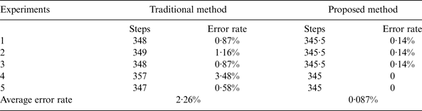
The step detection experiments were conducted in the New Main Building of Beihang University and the experimental scene is shown in Figure 6. The pedestrian walked along the designed straight path and walked one step across a floor tile. The total number of floor tiles was 345. Therefore the actual total number of steps was 345. Five repeat experiments were performed and the detailed results of the proposed step detection method and traditional method (Levi and Judd, Reference Levi and Judd1996) are shown in Table 1.
Figure 6. Experimental scene.
Table 1. Experimental results.
In all experiments conducted except the fourth one, the error rate of the traditional step detection method was around 1%. In Experiment 4 the pedestrian walked with deliberate forcefulness and a different step frequency in order to generate multiple false peaks in the accelerometer signal. Under these circumstances, the traditional method, with its fixed window length, erroneously detected several of these false peaks as steps, resulting in a higher error rate of 3·5%. One false peak marked by the arrow mark was detected as shown in Figure 7. In contrast, the adaptive dual-window step detection method was found to be capable of accurately counting steps (error rate ≤ 0·14%) regardless of the pedestrian's walking intensity. On coming to a stop the pedestrian brings both feet together, producing a final impact between the trailing foot and the ground. When the intensity of this final impact is sufficiently high, the vertical acceleration recorded by the IMU can be mistakenly identified as an extra peak by the proposed step detection algorithm (see Figure 8), resulting in a half- step being added to the total count. This effect can be seen in the step count results for the proposed method in Experiments 1 to 3 (see Table 1). Nevertheless, the repeated experiments have shown the overall step detection accuracy to be excellent.
Figure 7. One detected false peak.
Figure 8. Last detected mistakenly false peak.
4.3. Pedestrian Navigation Experiment and Analysis
The pedestrian navigation experiments were conducted in the New Main Building of Beihang University and the wearable model is shown in Figure 9. The IMU was worn at the waist back and it was worn as the pedestrian walked around a circular route as shown in Figure 9. The starting point was chosen on the sixth floor. Firstly, the pedestrian walked around the inside aisles and then went back to the starting point around the outside aisles. The pedestrian walked through buildings A, B, C, D, E, F, G and eventually returned to the starting point in building B. The sampling frequency of the system is 100 Hz and the first window length can be determined based on Equation (2).
Figure 9. Wearable equipment.
Additionally, in all positioning experiments, initial heading was determined by magnetometers and accelerometers on board the MTi-G-700. Gyros were used to real-time update heading during walking and heading was compensated with building heading (Abdulrahim et al., Reference Abdulrahim, Hide, Moore and Hill2011). Meanwhile, step length was determined by a nonlinear model of step length (Jahn et al., Reference Jahn, Batzer, Seitz, Patino-Studencka and Boronat2010; Weinberg, Reference Weinberg2002) and it required knowledge of previous measurements. Steps were detected by the method proposed in this paper.
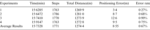
Figure 10 shows the positioning track calculated using output from the proposed step detection method. The calculated track was found to be very close to the pre-defined path, the final positioning error in this particular case being 3·4 m after a total journey of almost 1·3 km.
Figure 10. Positioning track.
Several experiments were performed and the starting point of all experiments was the same. The pedestrian walked back to the starting points in these experiments and the walked tracks were similar. All experimental results are shown in Table 2.
Table 2. Experimental results.
The values shown for each of the experiments are quite similar, as was expected, given that the pedestrian followed approximately the same circuital path in each case. The number of steps detected by the dual-window algorithm was roughly the same in each of the four experiments, ranging from 1763 to 1786, while the total distance travelled was also reasonably consistent. The slight differences between results can be understood as being due to variations in walking speeds, stride lengths and the actual path followed by the pedestrian in each of the experiments. Crucially the positioning error was relatively small – typically less than 10 m – after each walk lasting roughly 16 minutes. These results add support to our conclusion that the adaptive dual-window step detection method provides accurate and repeatable step count results for a pedestrian waist-worn INS (Inertial Navigation System).
5. CONCLUSION
This paper proposes an adaptive dual-window step detection method to restrain the interference from vibration and waist shaking. The method uses the relationship between periodic acceleration at a pedestrian's centre of gravity and walking stance while walking. Steps can be detected accurately by a dual-window peak detection method. The window length can be adjusted based on the change of step frequency, which improves the robustness of peak detection and eliminates false peaks. Step detection experiments and pedestrian navigation positioning experiments were performed. The experiment results demonstrate the proposed step detection method has high accuracy, good repeatability and improves the accuracy of step detection and pedestrian navigation positioning. Additionally, due to its simplistic algorithm, this simple yet very effective solution is appealing for a promising future autonomous low cost waist-worn INS.
ACKNOWLEDGEMENT
This work is supported by National Natural Science Foundation (NNSF) of China under Grant (61473019, 11202010, 61273033). The authors would like to thank the anonymous reviewers for their beneficial revision work in this paper.