


1. Introduction
A small object partially submerged in a liquid can create interfacial deformations due to surface tension. The deformed interface will result in capillary forces acting on the small object. This phenomenon is common in nature and is also important in practical applications, such as the behaviour of colloidal particles attached to liquid surfaces (Binks Reference Binks2002; Bormashenko Reference Bormashenko2011), the formation of liquid lenses (Aveyard & Clint Reference Aveyard and Clint1997), the mutual interaction (attraction or repulsion) between floating bodies (Bhatnagar & Finn Reference Bhatnagar and Finn2013; Ho, Pucci & Harris Reference Ho, Pucci and Harris2019) and the motion of water striders (Gao & Jiang Reference Gao and Jiang2004) and interfacial machines/robots (Barbot et al. Reference Barbot, Tan, Power, Seichepine and Yang2019; Basualdo et al. Reference Basualdo, Bolopion, Gauthier and Lambert2021). These examples can be classified into two groups according to the Bond number  $Bo$ (which measures the importance of gravity compared to surface tension): (i) for microscale bodies ( $Bo\to 0$), the interfacial deformations result from imposed contact angle or contact line conditions; and (ii) for mesoscale bodies ( $Bo\sim 1$), the interfacial deformations mainly result from the weight and buoyancy of the bodies (Kralchevsky & Nagayama Reference Kralchevsky and Nagayama2000). The former focuses mainly on the equilibrium positions and orientations of (anisotropic) particles at liquid interfaces, while the latter focuses on how capillary forces balance the weight of the bodies.
Many static configurations have been investigated for understanding how surface tension allows heavier-than-liquid particles to float (see Vella (Reference Vella2015a) for a review). One typical example is a floating cylinder with a circular cross-section, which is usually used for explaining the huge restoring forces provided by the superhydrophobic legs of water striders (Gao & Jiang Reference Gao and Jiang2004; Liu, Feng & Wang Reference Liu, Feng and Wang2007). It is easy to derive the force condition of the floating circular cylinder in analytical form through force analysis (Rapacchietta, Neumann & Omenyi Reference Rapacchietta, Neumann and Omenyi1977; Bhatnagar & Finn Reference Bhatnagar and Finn2006; Vella, Lee & Kim Reference Vella, Lee and Kim2006). Neglecting the weight in the force condition gives the restoring force as the cylinder changes its vertical location, and also determines the maximal restoring force corresponding to the largest density of the cylinder that can float in equilibrium. However, the maximal restoring force of a hydrophobic cylinder is insensitive to its contact angle, which implies that the load-bearing capacity of the strider's legs does not significantly benefit from its superhydrophobic property (Vella et al. Reference Vella, Lee and Kim2006; Liu et al. Reference Liu, Feng and Wang2007). Instead, the superhydrophobicity of the cylinder can dramatically reduce the detachment work (i.e. the energy required to lift the cylinder off the liquid surface) to promote the detachment of the cylinder (Lee & Kim Reference Lee and Kim2009).
Another important feature derived from the force condition is that there are two possible equilibrium positions of a floating cylinder (Bhatnagar & Finn Reference Bhatnagar and Finn2006). Assuming that two equilibria exist, their stabilities can be examined either by force analysis or by energy analysis (see e.g. Rapacchietta et al. Reference Rapacchietta, Neumann and Omenyi1977; Bhatnagar & Finn Reference Bhatnagar and Finn2006; Chen & Siegel Reference Chen and Siegel2018). The former provides a more intuitive but less rigorous interpretation of the stability. For example, as the cylinder sinks further into the liquid, the decrease of the vertical force will eventually cause the cylinder to sink, which corresponds to an unstable equilibrium. The latter predicts the stability by the variation of the total energy of the system in the context of the principle of virtual work. The two methods are equivalent to each other and provide the same stability criterion.
Regarding a non-circular cylinder, its irregular shape can influence not only the force condition, but also the moment condition, leading to a rotational stability problem. Liu et al. (Reference Liu, Feng and Wang2007) studied the force conditions of cylinders with elliptical and polygonal cross-sections, and showed that the strider's non-circular legs induced by elastic deformations create a greater restoring force than circular ones. For a free-floating non-circular cylinder, its equilibrium orientations also play a significant role in the maximal restoring force. For example, the load-bearing capacity of a lying elliptical cylinder (i.e. its major axis is parallel to the water line) is stronger than that of a standing cylinder (i.e. its minor axis is parallel to the water line) with the same shape. However, the rotational equilibrium of the standing cylinder is unstable, while the lying cylinder is rotationally stable (Zhang, Zhou & Zhu Reference Zhang, Zhou and Zhu2018). This implies that the floating elliptical cylinder will automatically adjust its orientation due to the total moment, and therefore its load-bearing capacity is evaluated based on the configuration of the lying cylinder. More generally, the rotational equilibria and their stabilities of a cylinder with an arbitrary convex cross-section are investigated without gravity (Raphaël et al. Reference Raphaël, Di Meglio, Berger and Calabi1992; Kemp & Siegel Reference Kemp and Siegel2011).
Zhang et al. (Reference Zhang, Zhou and Zhu2018) also studied cylinders with more irregular shapes by developing a mathematical model for calculating the force profile and the moment profile of a cylinder with an arbitrary cross-section. In this model, it is assumed that the cross-section of the cylinder is non-concave to fluids so that the meniscus (if it exists) can be determined uniquely by the cylinder's position. Conversely, a concave cylinder may permit multiple menisci. A concave part can lead to a jump (i.e. a discontinuous change) of contact line (Jansons Reference Jansons1985, Reference Jansons1986). In reality, whether the body is convex or not has a crucial influence on many floating phenomena. For instance, a hollow boat ( $Bo \gg 1$) that has a concave shape can float on water even though the density of its material is significantly larger than that of water, whereas a convex body ( $Bo \gg 1$) of the same material will sink into the water as predicted by Archimedes’ principle. For mesoscale cylinders ( $Bo\sim 1$), the concave shape may cause the instability of the meniscus on the concave part because the concave solid support weakens the meniscus stability (see e.g. Bostwick & Steen Reference Bostwick and Steen2015). Based on the above observations, one may suspect that the menisci around a cylinder with a concave shape may be multiple and some of them may be unstable.
Concave bodies at the fluid–fluid interfaces are common in nature, including some drift ices, seeds, leaves, branches, etc. Dumbbell particles may be fabricated due to the oriented assembly of anisotropic particles by capillary interactions (Lewandowski et al. Reference Lewandowski, Bernate, Tseng, Searson and Stebe2009). A soft solid can deform to concave shape with creasing patterns driven by capillarity (Mora et al. Reference Mora, Phou, Fromental, Pismen and Pomeau2010). Hegemann, Boltz & Kierfeld (Reference Hegemann, Boltz and Kierfeld2018) claimed that an elastic microcapsule with two liquids coexisting inside it can be compressed into a dumbbell shape due to the effect of liquid–liquid interfacial tension, but no further work on concave capsules at liquid–liquid interfaces has been conducted. The equilibrium configurations of Janus dumbbell and Janus spherocylinder or Janus ellipsoid at a fluid–fluid interface were investigated based on energy minimization (Park & Lee Reference Park and Lee2012; Anzivino et al. Reference Anzivino, Chang, Soligno, van Roij, Kegel and Dijkstra2019). The dynamics of two fused equal spheres driven along an interface between two immiscible fluids has been investigated asymptotically (Dörr & Hardt Reference Dörr and Hardt2015). Furthermore, hysteresis phenomena are common in numerous physical, mechanical, ecological and biological systems. They reflect memory effects and process irreversibility. The question of how the concavity of the cross-section of a cylinder affects the force condition and hysteresis of the concave cylinder still remains unanswered.
The magnitude of the capillary force is an important factor determining the potential rebounding height of a drop or a solid body at a liquid–gas interface, besides determining the floating or sinking of a solid body (Vella Reference Vella2015b). Water striders can jump on water by a large enough restoring force, which is produced by initially lowering its superhydrophobic legs to form a dimple. A large restoring force is needed for the jump on water (Vella Reference Vella2015b). Koh et al. (Reference Koh, Yang, Jung, Jung, Son, Lee, Jablonski, Wood, Kim and Cho2015) experimentally investigated the take-off velocity and force of the strider's legs and built a robotic insect jumping on water with maximum momentum transfer. Yang et al. (Reference Yang, Son, Lee, Jablonski and Kim2017) found that water striders adjusted leg movement speed to optimize take-off velocity for their morphology. Kim et al. (Reference Kim, Amauger, Jeong, Lee, Yang and Jablonski2017) analysed the mechanics of jumping on water. Chen et al. (Reference Chen, Liu, Lu and Ding2018) numerically simulated the entrapping and rebounding of an impacting sphere at a liquid–gas interface. Galeano-Rios et al. (Reference Galeano-Rios, Cimpeanu, Bauman, MacEwen, Milewski and Harris2021) studied the rebounds of capillary-scale superhydrophobic spheres on water. Lowering a superhydrophobic solid body to form a dimple on a water surface, as done by a water strider for jumping on water, is to generate a large enough restoring force (corresponding to large enough restoring potential energy) for rebound of the solid body. However, the magnitude of the restoring force for rebounds is not certain to be equal to that of the restoring force during the lowering stage, especially for a solid body with a concave shape. Accordingly, the force magnitude for hoisting and lowering solid bodies is an important problem and should be studied to determine the rebounding potential energy (defined as the work done by the restoring force during the whole hoisting process of an object) determining the potential rebounding height. Will the cross-section of a solid body influence the rebounding potential energy? How does a concave shape change the restoring force as hoisted?
In physics dominated by surface tension, there is possibly an optimal shape of solid–liquid interface. De Souza et al. (Reference De Souza, Brinkmann, Mohrdieck and Arzt2008), based on numerical simulations, found that the adhesion force possibly is modestly enhanced by dividing a fixed volume of liquid bridge between flat plates into many bridges between flat plates. By theoretical modelling, Butler & Vella (Reference Butler and Vella2022) found that splitting a fixed volume of liquid bridge between rough surfaces into many liquid bridges can significantly enhances the adhesion force by an order of magnitude. Will an optimal shape of the cross-section of a cylinder be reached for the maximum rebounding potential energy with a fixed volume of the cylinder under the effect of surface tension?
In order to answer the above interesting questions, this paper conducts theoretical research to determine the force condition of two typical concave cylinders (figure 1) with concave cross-sections. Section 2 theoretically determines the multiple possible menisci on two representative concave cylinders, and analyses the stabilities of the menisci. Section 3 investigates the hysteresis during the processes of hoisting and lowering the cylinder and conducts an analysis of the forces on the cylinder. Section 4 studies the rebounding potential energy and determines the optimal shape of the cross-section of a cylinder for the maximum rebounding potential energy. Finally, § 5 draws the main conclusions.

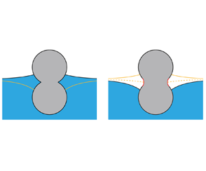
Figure 1. Schematics of horizontal cylinders with two representative concave cross-sections partly submerged into an unbounded liquid: (a) the boundary of the cross-section is always convex to fluids (the curvature of the solid boundary  $\bar {K}<0$) except at the two corners; and (b) the boundary has two concave parts ( $\bar {K}>0$) each lying between two inflection points. There are three types of forces acting on the cylinder: the surface tension force $\boldsymbol {F}_T$, the pressure force $\boldsymbol {F}_P$ due to pressure $p$, and the weight $\boldsymbol {F}_G$. In (a), the concave shape with a corner at an angle $\alpha \in (0,{\rm \pi} )$ is produced by overlapping two equal circular regions with a radius of R, with the distance D between the centre $O$ of the lower circle and the centre $O'$ of the upper circle; while in (b), the concave shape is produced by rounding the corners of the concave shape in (a) with two circles (red dashed curves) with a radius of r, where $\gamma$ is defined as the circular arc angle of the concave part and $\beta$ is the azimuthal angle at one junction of the concave and convex parts of the cylinder. In (a), the concave shape permits two possible menisci when the cylinder is positioned at a specific height $h$, and both of them are stable but only one can exist in reality. In (b), there are three possible menisci. The middle meniscus, which intersects the solid on the concave part, is unstable, whereas the other two menisci are stable. It should be noted that the coordinate system is fixed to the cylinder, and the water line (where the hydrostatic pressure $p=0$) is located at $y=-h$, so that the hydrostatic pressure is calculated by $p=-y-h$.
2. Multiple possible menisci and their stabilities
When a cylinder is at a given position, the multiple possible menisci on it means the existence of multiple solutions of the Young–Laplace equation. Among the multiple possible menisci, only the stable menisci can physically exist. In this section, we will investigate how concave shapes affect the number of menisci based on the two-dimensional Young–Laplace equation, and determine the stabilities of the menisci in terms of the geometrical arguments of the solid boundary.
2.1. Multiple possible menisci on concave cylinders
We consider a solid cylinder of density  $\rho _s$ with a concave cross-section partly submerged into an infinite liquid having density $\rho _l$ and surface tension $\sigma$ in a downward gravity field $g$. For the sake of simplicity, we choose to study the symmetric configurations in figure 1, because the menisci on the two sides of the cylinder are independent of each other. Here, two representative concave shapes are considered in this work: (i) the concavity of the region fused by two equal upper and lower circles is caused by a corner, which is a vertex of angle $\alpha \in (0,{\rm \pi} )$ where the slope of the boundary curve is discontinuous (figure 1a); and (ii) the concavity of the region fused by two equal upper and lower circles and rounded by another circle (its centre is located at the horizontal line of symmetry of the cross-section) is caused by a concave part (figure 1b). We exclude two special situations, i.e. bubble formation around the cylinder and drop attachment to the cylinder, when there are multiple intersection points of the solid and the menisci. We scale all lengths by the capillary length $l = \sqrt {\sigma /\rho g }$, pressure by $\rho gl$, areas by $l^{2}$, curvatures by $l^{-1}$, and forces by $\sigma$, where $\rho$ is the density difference $\rho =\rho _l-\rho _g$ between the liquid and the gas.
The origin of the Cartesian coordinates is located at the centre  $O$ of the lower circle before it is fused. As shown in figure 1, the concave cylinder positioned at a specific height $h$ (i.e. the distance from the water line to the origin of the Cartesian coordinates) may permit multiple possible menisci around itself. It is well known that all these menisci on the partially submerged cylinder satisfy the two-dimensional dimensionless Young–Laplace equation (Finn Reference Finn1986; Bhatnagar & Finn Reference Bhatnagar and Finn2016):
 \begin{equation} {\left( {\frac{{{u_x}}}{{\sqrt {1 + {u_x^{2}}} }}} \right)_x} = u, \end{equation}
where  $u(x)$ is the height of the meniscus from the water line located at $y=-h$ (i.e. the cylinder is positioned at height $h$ from the water line and $h$ is negative in the cases shown in figure 1), and the subscript $x$ refers to the derivative with respect to the coordinate $x$.
$x$.
Because the configuration is symmetric, we only consider its left side for simplicity. Integrating (2.1) with the condition of menisci at infinity,
 \begin{equation} u\to 0\quad\textrm{and} \quad u_x\to 0 \quad \textrm{as}\ x\to -\infty , \end{equation}
gives the meniscus shape (see e.g. Finn Reference Finn1986; Bhatnagar & Finn Reference Bhatnagar and Finn2006),
 \begin{equation} x-x_c=2\left(\cos{\psi\over 2}-\cos{\psi_c\over 2}\right)+ \ln\frac{\tan\dfrac{\psi}{4}}{\tan\dfrac{\psi_c}{4}}, \quad u = 2\sin \frac{\psi}{2}, \end{equation}
where the subscript  $c$ indicates the contact line (the contact point in two dimensions), and $\psi$ is the inclination angle of the meniscus measured anticlockwise.
The boundary of the concave cylinder is expressed by a parametric function  $\boldsymbol {r}(s)=(x(s),y(s))$, where $s$ denotes the arclength of the boundary. It is assumed that the parametrization is oriented clockwise so that the unit tangent vector of the boundary is $(\cos \varphi,\sin \varphi ) = (x'(s),y'(s))$, where the prime denotes the derivative with respect to $s$. Thus, the signed curvature of the solid boundary $\bar {K}={\mbox {d}\varphi }/{\mbox {d}s}<0$ for convex parts and $\bar {K}>0$ for concave parts (see figure 1b). Based on the Young–Dupré equation, all of the multiple possible menisci must yield the geometry constraint at the contact lines,
 \begin{equation} \psi_c + \theta =\varphi_c, \quad u_c - h =y_c, \end{equation}
where  $\varphi _c =\mbox {atan2}{(x'(s),y'(s))}$ is the inclination angle of the boundary of the cylinder at the contact lines and is measured anticlockwise. Here, $\mathrm {atan2}(X,Y)$ is a special kind of inverse tangent that takes into account the quadrant in which $(X,Y)$ lies and its range is $(-{\rm \pi},{\rm \pi} ]$.
Thus, from (2.3b) and (2.4), we can formulate the equation for determining the meniscus,
 \begin{equation} {\varphi(s)-\psi_c(s;h)-\theta=0}, \end{equation}
where
 \begin{equation} \varphi(s)=\mbox{atan2}{(x'(s),y'(s))}\quad\textrm{and} \quad \psi_c(s;h)=2\arcsin\frac{y(s)+h}{2}. \end{equation}
 When (2.5) has multiple solutions for a certain value of  $h$, there will be multiple possible menisci on the cylinder positioned at the height $h$. Zhang et al. (Reference Zhang, Zhou and Zhu2018) has shown that, when the cylinder has a convex shape, the meniscus can be determined uniquely by its height $h$. This conclusion can be easily explained by (2.5). When the cylinder has a non-concave shape (i.e. the curvature of the solid boundary $\bar {K}\leqslant 0$), the function $\varphi (s)$ is a non-increasing function, and it is also easy to see that the function $\psi _c(s;h)$ is a non-decreasing function with a fixed value of $h$. Therefore, the left-hand side of (2.5), $f(s;h)=\varphi (s)-\psi _c(s;h)-\theta$, is a non-increasing function, and then (2.5) has a unique solution (if it exists).
However, how the concavity of the cylinder leads to multiple possible menisci in the displacement process of the cylinder is not clear. To intuitively analyse the menisci on the concave cylinder in the displacement process, we will solve (2.5) with varying parameter  $h$ for two typical concave cylinders (see figure 2).

Figure 2. The inclination angle  $\varphi _c$ of the solid boundary at the contact line with respect to the height $h$ for (a) a concave cylinder with two corners and (b) each of concave cylinders with three different values of $r$. Here, $R=1$, $D=1.75$ and $\theta =5{\rm \pi} /9$. In (a), for some values of $h$, there are two possible menisci, respectively corresponding to two values of $\varphi _c$, where the upper (lower) meniscus corresponds to a higher (lower) value of $\varphi _c$. The inset in (b) shows an enlarged view of the $-1.055 \leqslant h \leqslant -1.045$ range. In (b), for $r=0.3613$ and $1.0112$, $\varphi _c(h)$ assumes multiple distinct values for some values of $h$, whereas for $r=1.5583$, $\varphi _c(h)$ has a unique value in its domain. Three typical configurations with different values of $r$ and $h=-1.047$ are shown by the insets, where the concave (convex) parts and the menisci meeting the concave (convex) parts are marked by red (black) solid lines.
2.1.1. Concave shapes with corners
Figure 1(a) shows a symmetric concave cylinder with two equal corners, which can be produced by gluing two equal truncated circular cylinders with a radius of  $R$, with the distance $D$ between the centres of the two truncated cylinders. Therefore, the configuration of the concave cylinder can be determined by the superposition of the configurations of the two truncated cylinders. The meniscus on a circular cylinder with the radius $R$ (figure 2c) has been well studied (see e.g. Chen & Siegel Reference Chen and Siegel2018), where the relationship between $\varphi _c$ and the height $h$ of the centre of the circular cylinder is given by
 \begin{equation} {h=2\sin \frac{{\varphi_c-\theta} }{2}-R\cos{\varphi_c}} \quad \textrm{for}\ \varphi_c\in[0,{\rm \pi}]. \end{equation}
It is noted that (2.7) is also derived from (2.3b) and the geometric constraint (2.4). Thus, (2.7) is equivalent to (2.5) for a circular cylinder. Because the right-hand side of (2.7),  $h(\varphi _c)$, is a strictly increasing function, its inverse function $\varphi _c(h)$ is also strictly increasing. Therefore, the meniscus on a circular cylinder can be determined uniquely by the height $h$.
$h$.
For the concave cylinder in figure 1(a), the relationship between  $\varphi _c$ and the height $h$ is given by
 $$\begin{gather} {h = 2\sin {{\varphi_c-\theta} \over 2}-R\cos{\varphi_c}} \quad \textrm{for}\ \varphi_c\in\left[\frac{\alpha}{2},{\rm \pi}\right], \end{gather}$$
 $$\begin{gather}{h = 2\sin {{\varphi_c-\theta} \over 2}-R\cos{\varphi_c}}-D \quad \textrm{for}\ \varphi_c\in\left[0,{\rm \pi}-\frac{\alpha}{2}\right], \end{gather}$$
where the angle of the corner is given by  $\alpha =2\arccos ({D}/(2R))$. Equation (2.8) is derived by considering the concave cylinder as two truncated circular cylinders, where (2.8a) and (2.8b) correspond to the lower and upper truncated cylinders, respectively.
With the aid of (2.8), we can plot the multivalued function  $\varphi _c(h)$ for $R=1$, $D=1.75$ and $\theta =5{\rm \pi} /9$, as shown in figure 2(a). The left and right curves in this panel are generated by (2.8b) and (2.8a), respectively. When the two curves have a common domain at some heights, the multivalued function $\varphi _c(h)$ assumes two distinct values of $\varphi _c$ in the common domain, which implies that there will be two possible menisci on the concave cylinder (see figure 2(a) for $h=-1.047$). To ensure the existence of the common domain, the angle $\alpha$ of the corner must satisfy $\alpha <{\rm \pi}$. In other words, the condition $\alpha <{\rm \pi}$ is a sufficient condition for multiple possible menisci. We note that the condition $\alpha <{\rm \pi}$ also leads to the concavity of the cylinder. Therefore, the concave cylinder in figure 2(a) must have two possible menisci for some values of $h$.
$h$.
2.1.2. Concave shapes with concave parts
Figure 1(b) shows a symmetric concave cylinder with two equal concave parts, produced by rounding the corners of the concave cylinder in figure 1(a) with two circles with a radius of  $r$. Therefore, when the menisci are on the convex parts of the cylinder, the relationship between $\varphi _c$ and the height $h$ has the same mathematical form as in the case of figure 1(a), given by
 $$\begin{gather} {h = 2\sin {{\varphi_c-\theta} \over 2}-R\cos{\varphi_c}} \quad \textrm{for}\ \varphi_c\in[\beta,{\rm \pi}], \end{gather}$$
 $$\begin{gather}{h = 2\sin {{\varphi_c-\theta} \over 2}-R\cos{\varphi_c}}-D \quad \textrm{for}\ \varphi_c\in[0,{\rm \pi}-\beta], \end{gather}$$
where the azimuthal angle at the lower junction of the concave and convex parts of the cylinder is given by  $\beta =\arccos ({D}/(2(R+r)))$. When the menisci are on the concave parts with a constant curvature $\bar {K}= 1/r$, from (2.3b) and (2.4b), we can obtain the relationship between $\varphi _c$ and $h$ for the concave parts as
 \begin{equation} {h=2\sin \frac{{\varphi_c-\theta} }{2}+r\cos{\varphi_c}}-\frac{D}{2} \quad \textrm{for}\ \varphi_c\in[\beta,{\rm \pi}-\beta]. \end{equation}
 With the aid of (2.9) and (2.10), we plot the function  $\varphi _c(h)$ for three different values of $r$ with $R=1$, $D=1.75$ and $\theta ={5{\rm \pi} /9}$, as shown in figure 2(b). In the three cases of $r = 0.3613$, $r =1.0112$ and $r =1.5583$, the changes in the number of menisci with changing cylinder height are qualitatively different from each other, represented by the function $\varphi _c(h)$. For $r =0.3613$, $\varphi _c(h)$ has three distinct values for each value of $h$ in some region, where the sub-function $\varphi _c(h)$ given by (2.10) is strictly increasing. For $r =1.5583$, $\varphi _c(h)$ is single-valued, where (2.10) defines a strictly decreasing function $\varphi _c(h)$. For an intermediate value $r =1.0112$, $\varphi _c(h)$ has up to five distinct values for some values of $h$, where (2.10) defines a multivalued function $\varphi _c(h)$. When the above cylinders are placed at a certain height $h$, each value of $\varphi _c$ corresponds to a possible meniscus. For instance, the concave cylinder with $r=1.0112$ positioned at $h=-1.047$ permits five possible menisci (see the middle inset of figure 2b), where three menisci are on the concave part.
The difference caused by different values of  $r$ mainly occurs in (2.10), which can be distinguished by the derivative $h'(\varphi _c )$. Consider $h$ as a function of $\varphi _c$ and then differentiating (2.10) with respect to $\varphi _c$ gives
 \begin{equation} h'(\varphi_c )={\cos \frac{{\varphi_c-\theta} } {2}-{r}\sin{\varphi_c}} \quad \textrm{for}\ \varphi_c\in[\beta,{\rm \pi}-\beta]. \end{equation}
When  $h'(\varphi _c ) < 0$ is always satisfied on the concave part, the function $\varphi _c(h)$ defined by (2.9) and (2.10) is single-valued. This implies that the meniscus on this cylinder can be determined uniquely by the cylinder height $h$, analogous to a convex cylinder. Therefore, $h'(\varphi _c ) \geqslant 0$ will be a criterion for determining whether the concave cylinder in figure 2(b) permits multiple possible menisci. When $h'(\varphi _c ) > 0$ is always satisfied, (2.9) and (2.10) will have a common domain, leading to multiple values of $\varphi _c$, though the sub-function $\varphi _c(h)$ given by (2.10) is single-valued. When $h'(\varphi _c )$ is allowed to change its sign on the concave part, the sub-function $\varphi _c(h)$ given by (2.10) is multiple-valued.
Based on the above observations, the critical radius of concave arc  $r^{*}$ (corresponding to the critical angle of the concave circular arc $\gamma ^{*}$, see figure 6a) for multiple possible menisci can be found by solving
 \begin{equation} \max(h'(\varphi_c ))=0. \end{equation}
For  $R=1$, $D=1.75$ and $\theta =5{\rm \pi} /9$, the critical value given by (2.12) is $r^{*}=1.0919$. This indicates that only the concave cylinders with $r < r^{*}$ in figure 1(b) can permit multiple possible menisci, consistent with the cases in figures 2(b) and 5.
It is interesting that, if  $h'=0$ always holds on an interval of $\psi _c$, the corresponding cylinder with an appropriate height will have infinitely many possible menisci on this interval. The property that there exists an entire continuum of distinct menisci on a special solid support has been exploited for several different configurations, e.g. the exotic container (Concus & Finn Reference Concus and Finn1991) and the exotic capillary tube (Wente Reference Wente2011). As the name suggests, the former is a container with a specific axisymmetric shape and with a certain volume of liquid that admits infinitely many possible menisci in it. By contrast, the latter is a specific axisymmetric capillary tube placed at an appropriate height in an infinite liquid that also has the above ‘exotic’ property with a pressure constraint. In our case, the boundary of the cylinder having the ‘exotic’ property can be seen as an exotic wall analogous to the exotic capillary tube, the curvature of which satisfies $h'=0$. Its shape can be obtained analytically (Zhang & Zhou Reference Zhang and Zhou2020).
Generally, there are different capillary forces on the surface of a Janus particle, which can cause the surface tension imbalance. The surface tension imbalance can induce the twisting of a Janus cylinder (Oratis, Farmer & Bird Reference Oratis, Farmer and Bird2017). The surface tension imbalance also can induce self-powered locomotion of a hydrogel water strider (Zhu et al. Reference Zhu, Xu, Wang, Pan, Qu and Mei2021) or an isotropic particle with different surface tension coefficients on its surface (for example, a partially submerged cylinder having surface tension imbalance; see Janssens, Chaurasia & Fried (Reference Janssens, Chaurasia and Fried2017)). Even if convex to the fluids, a Janus particle, half of which has a different contact angle from the other half, possibly has a jump of contact line at its surface when it moves through a fluid–fluid interface. We find that a jump of contact line occurs as a Janus cylinder is gradually lowered or hoisted by keeping the upper part hydrophilic and the lower part hydrophobic (figure 3a), which also should cause a change of rebounding capacity. We will compare the effects of concave shapes and Janus convex feature on the jump of contact lines and characteristics of multiple menisci (see figure 3).

Figure 3. Multiple menisci (the first column) on (a) a Janus (convex) circular cylinder, (b) a concave cylinder with corners, and (c,d) two concave cylinders with concave parts with different radii, (c)  $r=0.3613$ and (d) $r=1.0112$. For the Janus circular cylinder, $R=1.5$, and $\theta _u=4{\rm \pi} /9$ for the upper part and $\theta _l=5{\rm \pi} /9$ for the lower part; while for the three concave cylinders, $R=1$, $D=1.75$ and $\theta =5{\rm \pi} /9$. In the first column, the concave (convex) parts and the stable menisci meeting the concave (convex) parts are marked by red (black) solid lines, and the unstable menisci meeting the concave parts are marked by red dashed lines. The height dependence of the geometric parameters: the intersection angle $\omega$ between the meniscus and the solid (the second column), the difference ${\bar {K}}-{\bar {K}}^{*}$ (the third column), and the difference ${\bar \chi }_1-\chi _1^{*}$ (the last column), where the intersection angle $\omega$ is given by (2.15), ${\bar {K}}$ and ${\bar {K}}^{*}$ are the signed curvatures of the solid and the exotic cylinder given by (2.14) and (2.17), respectively, and ${\bar {\chi }}_1$ and $\chi _1^{*}$ are the new boundary parameter and the critical value given by (2.21) and (2.20), respectively. Grey solid (dashed) lines represent the segments for $\omega '(y)<0\ (\omega '(y)>0)$ corresponding to stable (unstable) menisci. Circles (solid points) are the unstable (stable) solutions. Remarkably, a Janus circular cylinder with hydrophobic upper part and hydrophilic lower part can only permit a unique meniscus for any value of $h$ and may be pinned at the joint edge, which is different from the case of (a) and similar to that of a uniform convex cylinder with sharp edge (Zhang et al. Reference Zhang, Zhou and Zhu2018). So the graphs for this case have not been given in this figure.
2.2. Stabilities of multiple menisci
As shown in figure 3, the menisci around the cylinder are not unique and only stable menisci can physically exist. The methods to determine the stability are generally based on minimizing the system's total energy functional: the equilibrium is stable when the minimum of the second variation of the total energy over all admissible perturbations is positive, and is unstable when it is negative (Slobozhanin & Alexander Reference Slobozhanin and Alexander2003). Two types of constraint on the bulk, i.e. volume constraint and pressure constraint, can influence the meniscus stability. The volume constraint means that the total volume (area in the two-dimensional case) of the liquid is fixed, corresponding to volume perturbations. The pressure constraint means that the reference pressure is held constant, corresponding to pressure perturbations. The volume perturbations with pinned contact line (contact point in the two-dimensional case) is the least dangerous for stability, while the pressure perturbations with free contact line is the most dangerous (Bostwick & Steen Reference Bostwick and Steen2015).
In this work, as the stability problem is two-dimensional, the only admissible perturbation is in the plane and the corresponding total energy functional is considered. Besides, the type of constraint is the pressure constraint (because of infinite liquid) with a free contact point. Thus, the stability of an equilibrium meniscus can be given by comparing the boundary parameter  $\chi _1$ and its critical value ${\chi _1}^{*}$, that is, the equilibrium meniscus will be stable if $\chi _1>{\chi _1}^{*}$, and unstable if $\chi _1<{\chi _1}^{*}$ (Myshkis et al. Reference Myshkis, Babskii, Kopachevskii, Slobozhanin, Tyuptsov and Wadhwa1987; Slobozhanin & Alexander Reference Slobozhanin and Alexander2003), which can be derived from the associated eigenvalue problem for the second variation of the total energy (see Appendix A). In the following, the parameters related to the meniscus are defined at the contact point, and the subscript $c$ of these parameters is omitted for convenience.
The boundary parameter  $\chi _1$ of the solid at the contact point is given by (see e.g. Slobozhanin & Alexander Reference Slobozhanin and Alexander2003)
 \begin{equation} {\chi_1=\frac{{K \cos{\theta}-\bar{K}} }{{\sin{\theta}}}}, \end{equation}
where  $K= 2\sin (\psi /2)$ is the curvature of the liquid at the contact point, and the curvature $\bar {K}$ of the solid boundary $x(y)$ can be written as
 \begin{equation} {\bar{K}} ={-}\frac{{x''(y)} }{{(1 + {({x'(y)})^{2}})^{3/2}}}, \end{equation}
where  ${\bar {K}} < 0$ $({\bar {K}} > 0)$ if the solid is convex (concave) to the liquid. The critical value ${\chi _1}^{*}$ can be determined based on the exotic cylinder whose boundary parameter $\chi _{e,1}$ is equal to ${\chi _1}^{*}$ (Zhang & Zhou Reference Zhang and Zhou2020), and the process of obtaining $\chi _{e,1}$ is presented as follows.
Giving the expression of the intersection angle  $\omega$ between the meniscus and the solid boundary as $\omega (y)=\varphi (y)-\psi (y)$, and substituting (2.6a,b) into it, we have
 \begin{align} {\omega(y)={\mathrm{atan2}}(1,x'(y))-2\arcsin \frac{y+h }{2}\quad \mbox{for}\ y \in [ \max({-}2,h-R) ,\min(2,h+D+R) ].} \end{align}
It is noted that the relation  $\omega (y)=\theta$ is satisfied at the contact point. The intersection points of the curve denoting the function $\omega (y)$ and the straight line $\omega = \theta$ are just the contact points that correspond to the equilibrium menisci (figure 3).
The exotic cylinder permits an entire continuum of equilibrium menisci on it, i.e.  $\omega (y)=\theta$ is always satisfied for an exotic cylinder. Differentiating $\omega (y)$ and setting $\omega '(y)=0$ for the exotic cylinder, we obtain
 \begin{equation} {\omega'(y) \equiv{-}\frac{{x''} }{{1 + {{x'}^{2}}}} - \frac{2 }{{\sqrt {4 - {(y+h)^{2}}} }}=0} \end{equation}
at the stationary points of  $\omega (y)$. Comparing (2.14) and (2.16) gives the curvature of the solid boundary at the stationary point,
 \begin{equation} {{\bar{K}}^{*} =\frac{2 }{{\sqrt {(1 + {{x'}^{2}})(4 - {(y+h)^{2}})} }}}, \end{equation}
which is also an expression for the curvature of the exotic cylinder in two dimensions. From (2.14), (2.16) and (2.17), we have
 \begin{equation} { \omega'(y)= { {\sqrt{1 + {{x'}^{2}}}}\,(\bar{K}-{\bar{K}}^{*}) }}. \end{equation}
Substituting  $x'=\cot \varphi$ and $y = 2\sin ({\psi }/{2})-h$ into (2.17), we obtain the curvature of the exotic cylinder in two dimensions expressed in terms of $\psi$ and $\theta$ as
 \begin{equation} {\bar{K}_e=\frac{\sin{(\psi + \theta)} }{{ \cos\dfrac{\psi }{2}}}}. \end{equation}
Substituting  $K= 2\sin ({\psi }/{2})$ and (2.19) into (2.13), the boundary parameter of the exotic cylinder $\chi _{e,1}$ (i.e. the critical value ${\chi _1}^{*}$) is obtained as
 \begin{equation} {{\chi_1}^{*}(y)={-}\frac{\cos{\psi} }{\cos\dfrac{\psi }{2}}=\frac{{{(y+h)^{2}}- 2} }{{\sqrt {4 - {(y+h)^{2}}} }}}, \end{equation}
which is independent of  $\theta$, only depending on $\psi$ (or $y$).
$y$).
We could directly determine the stability of equilibrium menisci by comparing  $\chi _1$ (calculated from (2.13)) and ${\chi _1}^{*}$ (calculated from (2.20)) at the position satisfying $\omega (y)=\theta$, but on account of the need for clarity of presentation, in this paper, we introduce a new boundary parameter of the solid (similar to (2.13)) as
 \begin{equation} {{\bar{\chi}_1(y)} = \frac{{K \cos{\omega}-\bar{K}}}{{\sin{\omega}}}}, \end{equation}
which is equal to  $\chi _1$ when $\omega (y)=\theta$. The new parameter $\bar {\chi }_1(y)$, which completely depends on the function of the solid boundary $x(y)$, can be calculated along the solid boundary. By comparing $\bar {\chi }_1$ and ${\chi _1}^{*}$, the stabilities of the menisci can be determined, and the solid boundary can be distinguished into different regions according to the stabilities of the menisci (see figure 3). Because the range of the contact angle considered in this problem is between $0$ and ${\rm \pi}$, only the range $\omega (y)\in (0,{\rm \pi} )$ needs to be investigated here. Therefore, from (2.15), (2.18), (2.20) and (2.21) we observe that ${\bar {\chi }_1}<{\chi _1}^{*}$ and $\omega '(y)>0$ if ${\bar {K}}>{\bar {K}}^{*}$, and that ${\bar \chi _1}>{\chi _1}^{*}$ and $\omega '(y)<0$ if ${\bar {K}}<{\bar {K}}^{*}$. Accordingly, the stabilities of the menisci also can be determined by comparing ${\bar {K}}$ and ${\bar {K}}^{*}$ or by comparing $\omega '(y)$ and $0$.
$0$.
As formulated above, the equilibria and stabilities of the menisci are given in terms of geometrical arguments. We also calculate directly the total energy of the system with the contact point gradually changing and relate the positions of the equilibria of the menisci and the stabilities of the equilibria to the energy. The positions of the minima and maxima of the curve of the total energy with the  $y$ value of the contact point coincide with the positions of the stable and unstable equilibria calculated by the method in terms of geometrical arguments, respectively (see Appendix B).
To illustrate how to determine the number and stability of the menisci on different concave cylinders by using the method based on geometrical arguments, let us consider representative simple examples: a concave cylinder with corners (the second inset in figure 2a), and two concave cylinders each having concave parts with different radii  $r = 0.3613$ (the first inset in figure 2b) and $r = 1.0112$ (the second inset in figure 2b) in comparison with a Janus (convex) circular cylinder with the hydrophilic upper part and hydrophobic lower part (see figure 3). Here, the cases (the first and third insets in figure 2a and the third inset in figure 2b) that only permit a unique meniscus (it must be stable) at a height $h$ have not been analysed.
Figure 3(c,d) shows that there are three (five) distinct menisci, all of which intersect the solid at the contact angle  $\theta ={5{\rm \pi} /9}$. As discussed above, the curvature ${\bar {K}}$ of the solid boundary $x(y)$ is compared to the critical curvature ${\bar {K}}^{*}$ for determining the sign of $\omega '(y)$ and the meniscus stability. In figure 3(b), the concave cylinder with corners permits two possible menisci when the cylinder is positioned at a specific height (e.g. $h=-1.047$), and both of them are stable because the solid boundary is convex to fluids, but only one can exist in reality. This concave case with corners is generally analogous to a Janus convex cylinder with hydrophilic upper part and hydrophobic lower part at $h=0$.
In figures 3(c) and 3(d), the parts with  $\omega '(y)>0$ and $\omega '(y)<0$ appear alternately. There is at most one stable (or unstable) meniscus on one segment with $\omega '(y)<0$ (or $\omega '(y)>0$) (i.e. between two neighbouring stationary points of $\omega (y)$). Thus, the stable and unstable menisci occur alternately. In this case, for a small value of $r$ (e.g. $r=0.3613$), there are two stable menisci meeting the convex part and one unstable meniscus meeting the concave part and staying between the two stable menisci, while for a large value of $r$ (e.g. $r=1.0112$), there are two stable menisci meeting the convex part, two unstable menisci meeting the concave part and lying between the two stable menisci, and one stable meniscus meeting the concave part and lying between the two unstable menisci.
The above findings for the cases in figure 3 seem to suggest the general fact that, when  $\omega (y)$ is smooth, the stable and unstable menisci appear alternately on the solid surface $x(y)$ containing a concave part if the menisci are multiple.
3. Hysteresis effect and force analysis on a concave cylinder
The stable menisci of the multiple possible menisci on a cylinder at a given position were determined in the previous section. However, only one of the stable menisci actually exists in reality when vertically moving the cylinder. Hysteresis (i.e. the dependence of the state of a system on its history) may exist when hoisting and lowering the cylinder. The hysteresis plays an important role in determining which stable meniscus actually exists during the processes of hoisting and lowering the cylinder. With the determination of the existing meniscus, the forces on the cylinder can be obtained. In this section, we will study the hysteresis effect to determine the existing meniscus and analyse the forces exerted on a concave cylinder during the processes of gradually hoisting and lowering the cylinder, and present the results in the form of bifurcation diagrams and force–distance curves representing the relation between the restoring force and the position of the cylinder.
3.1. Hysteresis effect and determination of existing meniscus
Motivated by Huh & Mason (Reference Huh and Mason1974), who investigated an axisymmetric floating body under surface tension effects, we consider an infinitesimal vertical displacement  $\delta h$ of the cylinder in figure 1 (in the coordinate system fixed to the liquid), and then the function for the solid surface is $x(y-\delta h)$ for $y \in [h-R+\delta h,h+R+D+\delta h]$. As suggested by Zhang et al. (Reference Zhang, Zhou and Zhu2018), considering the above configuration in the coordinate system fixed to the solid (i.e. setting $y=\tilde {y}+\delta h$ and $x=\tilde {x}$ so that the pressure in the liquid is $p=-\tilde {y}-\delta h$) is more conducive to analysis, because the function for the solid surface remains as $\tilde {x}(\tilde {y})$ for $\tilde {y} \in [h-R,h+R+D]$.
In the following, the configuration will be investigated in the coordinate system fixed to the solid and we will drop the tildes. In response to the infinitesimal displacement  $\delta h$, the meniscus will adjust itself slightly, and meanwhile the contact point $(x_c,y_c)$ will experience an infinitesimal displacement $(\delta x_c,\delta y_c)$. The linear relation between $(\delta x_c,\delta y_c)$ and $\delta h$ is given by (Zhang et al. Reference Zhang, Zhou and Zhu2018)
 $$\begin{gather} \left[ {\bar{K} \cos {\psi \over 2} - \sin (\psi + \theta )} \right]\delta y_c = \sin (\psi + \theta )\delta h, \end{gather}$$
 $$\begin{gather}\left[ {\bar{K} \cos {\psi \over 2} - \sin (\psi + \theta )} \right]\delta x_c = \cos (\psi + \theta )\delta h. \end{gather}$$
This relation tells us that, if we have determined a stable meniscus on a part of the solid boundary  $x(y)$ with ${\bar {K}}<{\bar {K}}^{*}$, after an infinitesimal displacement $\delta h$ the stable meniscus will adjust itself slightly (according to (3.1)) to accommodate the solid surface because of the pressure variation $-\delta h$. The same is true for an unstable meniscus on a solid part with ${\bar {K}}>{\bar {K}}^{*}$. Therefore, if the number of menisci does not change during the infinitesimal change, which meniscus exists after an infinitesimal change can be determined by the relation (3.1) and the former existing meniscus.
Then we investigate how the number of menisci changes with the cylinder height  $h$, which is related to the bifurcation theory (Seydel Reference Seydel2009). Considering a vertical displacement $-h$ of the water line in the coordinate system fixed to the solid, the pressure is $p=-y-h$. Thus, the function for determining the equilibrium menisci is
 \begin{equation} f(y,h)=\omega(y,h)-\theta. \end{equation}
The equilibria will be found when  $f=0$. Differentiating (3.2) with respect to $h$ gives
 \begin{equation} f_h(y,h)={-}(1 - (h + y)^{2} /4)^{{-}1/2}. \end{equation}
From here onwards, the subscripts ‘ $y$’ and ‘ $h$’ denote differentiation. From § 2.2, we recall that the meniscus is stable if $f_y<0$, and unstable if $f_y>0$. Similar to the dynamical system with a fold bifurcation, two solutions are born or annihilate each other at the bifurcation point $(y_b,h_b)$ where $f(y_b,h_b)=0$, $f_y(y_b,h_b)=0$, $f_h(y_b,h_b)\not =0$ and $f_{yy}(y_b,h_b)\not =0$ are satisfied (Seydel Reference Seydel2009). With the help of (3.3) it can be easily seen that the inequality $f_h(y_b,h_b)<0$ persists at any position on branches of extremals. Based on the properties of fold bifurcations and with the inequality $f_h(y_b,h_b)<0$, we can derive that, if $f_{yy}>0$, there are locally two solutions at the side, $h>h_b$, of a bifurcation point and there is no solution on the other side; and if $f_{yy}<0$, two solutions occur at the side $h< h_b$ (see figure 4a,b). Figure 4(a,b) also shows that the two solutions $y_1$ and $y_2$ are stable and unstable, respectively, with $y_1< y_b< y_2$ if $f_{yy}>0$ (with $y_1>y_b>y_2$ if $f_{yy}<0$). Moreover, we also observe that the lower branch of extremals in a fold opening to the right corresponding to $f_{yy}>0$ and the upper branch in a fold opening to the left corresponding to $f_{yy}<0$ are stable, while the other branches are unstable. Therefore, the shape of a fold in a bifurcation diagram can be used to predict the stabilities of the menisci.

Figure 4. Schematics of fold bifurcations of the contact points of menisci: (a,b) a simple fold and (c) two successive simple folds. The solid line and dashed line denote stable and unstable solutions, respectively. In (a,b), the solid points denote the bifurcation points  $(y_b,h_b)$. In (c), blue (green) arrows denote that a cylinder moves into (out from) the liquid, and dotted lines denotes the jump phenomena of menisci. The parts $h \in [h_2, h_3]$ of branches form a sharp hysteresis loop.

Figure 5. (a) All the phases for different values of r changing from 0 to  $\infty$, and (b–i) bifurcation diagrams corresponding to (2.14) for (b) the case $r = 0$ (the concave cylinder with two corners) and the cases (c) $r = 0.3613$, (d) $r = 1.0032$, (e) $r = 1.0112$, ( f) $r = 1.0199$, (g) $r = 1.0273$, (h) $r=1.0558$ and (i) $r = 1.5583$, respectively representing phases 1–7 for the cylinder with concave parts ( $R=1$, $D=1.75$ and $\theta =5{\rm \pi} /9$). Solid (dashed) lines denote that the menisci are stable (unstable). In (a), $\gamma ^{+}$ is determined by solving $\min (h'(\varphi _c ))=0$, and $\gamma ^{*}$ is determined by (2.12). In (b), there is not a fold bifurcation but jumping phenomena. In (c,h), there are two fold bifurcations so that a one-fold hysteresis loop $A$ can be formed and three menisci may exist at some heights. In (d–g), there is a two-fold hysteresis loop $B$ which consists of two one-fold hysteresis loops. However, during the lowering and hoisting processes of the cylinder, the middle two bifurcation points are bypassed in (d), and the lower one of the middle two bifurcation points is bypassed in (e). In (d–f) at most five menisci may exist at some heights, while in (g) at most three menisci may exist at some heights. In (i), there is not a fold bifurcation or jumping phenomenon because the large value of $r$ only permits a unique meniscus at all values of $h$, which is analogous to a convex cylinder (Zhang et al. Reference Zhang, Zhou and Zhu2018). A typical one-fold hysteresis loop $A$ is highlighted by a yellow box in (c) and a typical two-fold hysteresis loop $B$ is highlighted by a brown box in (e). We note that the heights of all the bifurcation points in each of (d–h) have very small difference, different from in (c). This is mainly attributed to too small horizontal domain of the concave part. By calculation, we find that changing the shape of the concave part to enlarge its horizontal domain (for example, using the cylinder cross-sectional shape with a given function of the solid boundary $x(y) = 0.15\cos (2{\rm \pi} y)$) can lead to a large difference in the heights of the bifurcation points as mentioned above. However, the change in the shape of the concave part never influences the findings of this paper.
For the configurations of the cylinders as shown in figure 1, there is a horizontal symmetry axis  $y = D/2$, and from (2.15), we obtain $\omega (y,h) = {\rm \pi}- \omega ( - y + D, - h - D)$. Then, the relation can be given by
 \begin{equation} f(y,h;\theta ) ={-} f( - y + D, - h - D;{\rm \pi} - \theta ), \end{equation}
which implies that, once an equilibrium meniscus on a cylinder with a contact angle  $\theta$ is found at a position ( $y,h$), there must be an equilibrium meniscus on the cylinder with the same geometry and the contact angle ${\rm \pi} - \theta$ at the position ( $-y+D, -h-D$) and the liquid–cylinder system is symmetrical to the liquid–cylinder system with the parameters ( $y,h;\theta$) over the undisturbed water line. The equilibria and stabilities of the menisci on a cylinder with the contact angle ${\rm \pi} - \theta$ can also be derived from those of the menisci on the cylinder with the contact angle $\theta$ that can be obtained with the bifurcation diagrams.
Fold bifurcations are usually associated with hysteresis effects. Characteristics for hysteresis effects are jump phenomena, which take place at bifurcation points (Seydel Reference Seydel2009). Suppose that there are multiple stable menisci when the cylinder rises to a certain height  $h\in (h_2,h_3)$; then the solutions of $f(y,h)=0$ for this configuration may form a sharp hysteresis loop which consists of two successive simple folds, as shown in figure 4(c). The jump phenomena of menisci can be explained as follows. Let us imagine two opposite processes: hoisting the cylinder from $h_1$ to $h_4$ (green arrows) and lowering the cylinder from $h_4$ to $h_1$ (blue arrows).
When the cylinder is placed at the height  $h_1$, the meniscus at the left side of the cylinder is unique, which corresponds to a stable solution on the upper branch. Hoisting the cylinder to $h_2$, the meniscus varying with $h$ adjusts itself according to (3.1). Then, a fold bifurcation occurs at $h_2$, and two solutions are born, one of which is unstable corresponding to the middle branch and the other is stable corresponding to the lower branch. From $h_2$ to $h_3$, the existing meniscus changes smoothly following the upper branch. Meanwhile, the upper branch and the middle branch gradually approach each other and merge eventually at $h_3$, which is the second fold bifurcation. If we continue to hoist the cylinder, the contact point of the meniscus will jump from the upper branch to the lower branch at the bifurcation point. The jump phenomenon of the meniscus can cause transient phenomena, including shock and oscillation. Discussions about transition phenomena are beyond the scope of this paper.
Considering lowering the cylinder from  $h_4$ to $h_1$, the change of the meniscus is similar to that from $h_1$ to $h_4$, while the meniscus changes following the lower branch for $h\in (h_2,h_3)$.
Therefore, the solutions for hoisting and lowering the cylinder form a sharp hysteresis loop with  $h\in [h_2,h_3]$ in figure 4(c). The jump phenomena of the meniscus are also observed for the capillary action in an ink bottle which has smaller radii at the neck portion and larger radii for the rest of the shape, known as the ‘ink-bottle’ effect (Aylmore Reference Aylmore1974).
3.2. Forces on a cylinder
After determining the existing menisci, the forces acting on the cylinder can be determined. There are three forces (see figure 1): the surface tension force  $\boldsymbol {F}_T$ exerted by the surface tension at the contact points, the pressure force $\boldsymbol {F}_P$ exerted by the pressure of the liquid, and the weight $\boldsymbol {F}_G$. Let $\boldsymbol {F}_S$ be the sum of $\boldsymbol {F}_T$, $\boldsymbol {F}_P$ and $\boldsymbol {F}_G$. Because the configuration considered is assumed to be symmetric, the horizontal components of $\boldsymbol {F}_T$ and $\boldsymbol {F}_P$ are zero. It is noted that the horizontal component of $\boldsymbol {F}_S$ is always zero whether the configuration is symmetric or not, because the sum of the horizontal components of $\boldsymbol {F}_T$ and $\boldsymbol {F}_P$ at one side is constant regardless of the meniscus shape (Mansfield, Sepangi & Eastwood Reference Mansfield, Sepangi and Eastwood1997; Keller Reference Keller1998; Finn Reference Finn2010). However, the horizontal resultant force will be non-zero if considering a surface tension imbalance on the cylinder (Janssens et al. Reference Janssens, Chaurasia and Fried2017).
Considering a vertical displacement  $-h$ of the water line for the configuration in figure 1, the surface tension force, the pressure force and the weight are given by
 \begin{equation} \boldsymbol{F}_T={-}2\sin\psi\,\boldsymbol{e}_y, \quad \boldsymbol{F}_P={-}\int_{{\varSigma _W}} {p\boldsymbol{n}\,{\mathrm{d}}S} \quad {\rm and} \quad \boldsymbol{F}_G={-}\frac{{\rho_s}}{\rho}\,|\varOmega|\boldsymbol{e}_y, \end{equation}
respectively, where  $\varSigma _W$ denotes the wetted surface of the cylinder, $\boldsymbol {n}$ is the unit normal to the surface of the cylinder, directed into the liquid, $\rho _s$ is the cylinder density and $|\varOmega |$ is the area of the cylinder cross-section $\varOmega$. Applying Green's theorem, the integral of pressure on the wetted surface can be rewritten as (Mansfield et al. Reference Mansfield, Sepangi and Eastwood1997; Keller Reference Keller1998)
 \begin{equation} {-\int_{{\varSigma_W}} {p\boldsymbol{n}\,{\mathrm{d}}S} =\int_{{\varSigma_W}}{(y+h)\boldsymbol{n}\,{\mathrm{d}}S} =|\varOmega_{W}|\boldsymbol{e}_y}, \end{equation}
where  $\varOmega _W$ is the domain bounded above by the undisturbed water line $y=-h$, below by $\varSigma _W$, and laterally by two vertical line segments between the contact points and $y=-h$. The above calculation of the pressure force is analogous to the buoyancy in Archimedes’ principle, which equals the weight of the displaced liquid.
Then, the vertical resultant force  ${F}_S^{v}$ is written as
 \begin{equation} {{F}_S^{v}={F}_R+{F}_G ={-}2\sin\psi+|\varOmega_W|-\frac{{\rho_s}}{\rho }|\varOmega|}, \end{equation}
where  ${F}_R=-2\sin \psi +| \varOmega _W |$ is the total restoring force arising from the surface tension on the contact points and the hydrostatic pressure acting on the wetted surface.
3.3. Bifurcation diagrams and force–distance loops
As shown in figure 3, the number and the stabilities of the menisci on concave cylinders and the conditions of the contact line jumping can be changed by varying the radius r. In the following, the general relations in §§ 3.1 and 3.2 will be illustrated by explicit calculations for concave cylinders with different cross-sectional shapes (see figure 5). Representative parameters of the concave cylinders  $R = 1$, $D = 1.75$ and $\theta = 5{\rm \pi} /9$ are selected, for which the maximum possible bifurcation phases of the cases $\theta \geqslant {\rm \pi}/2$ appear. As illuminated by (3.4), if an equilibrium meniscus exists on a cylinder with a contact angle $\theta$, there must be an equilibrium meniscus on the cylinder with the contact angle ${\rm \pi} - \theta$ and the liquid–cylinder system is symmetrical to the system with the contact angle $\theta$ over the undisturbed water line. Accordingly, the cases $\theta <{\rm \pi} /2$ will not be considered in this work. The range of the vertical displacement of the concave cylinders is $h\in [-4.276, 2.286]$ to ensure that the whole process of vertical translation (hoisting and lowering) of the cylinder is included.
By numerically solving  $f(y,h)=0$ with the solid boundary, we obtain the diagram of all the phases for different values of r changing from 0 (cross-section with two corners) to $\infty$ (laterally planed cross-section) and the bifurcation diagrams for the equilibrium menisci for several values of r representing different phases, as shown in figure 5. We note that a branch of bifurcation diagrams can also be obtained by integrating (3.1) with a solution on this branch as initial conditions. Considering that the number of phases is too many, we take the cases $r=0.3613$ and $r=1.0112$ as examples to analyse the one-fold hysteresis loop and the two-fold hysteresis loop, respectively.
Figure 5(c) shows that there is only one curve segment in the bifurcation diagram which has two fold bifurcations for the case  $r=0.3613$. The two fold bifurcations form a one-fold hysteresis loop (the loop $A$ is highlighted by the yellow box in figure 5c), where the two bifurcation points are located at $h=h_3$ and $h_2$ in the order that they appear on the curve. As discussed in § 3.1, the stabilities of menisci can be determined by the shape of the fold bifurcation. We can see that there are three branches of extremals divided by the bifurcation points, which take turns to be stable and unstable.
Different from the case  $r=0.3613$, for the case $r=1.0112$, there is a two-fold hysteresis loop $B$ (highlighted by the brown box in figure 5e) when lowering the cylinder, while there is a one-fold hysteresis loop when hoisting the cylinder. The two-fold hysteresis loop $B$ consists of two coupled one-fold hysteresis loops (see the yellow boxes in figure 5e), which have a common region with $h$ lying between $h_3$ and the height of the lower one of the middle two bifurcation points. In this region, there are at most five solutions of $f(y,h)=0$. Additionally, regardless of lowering or hoisting the cylinder, the lower one of the middle two bifurcation points is bypassed. From the above observations, it is not hard to see that, for the case $r=1.0112$, we can obtain arbitrary $n$-fold hysteresis loop by adjusting the shape of the concave domain of the solid boundary $x(y)$, for example, by using a shape of multiple successive concavities at one side because of the periodicity of concavity and convexity.
In contrast to a partially submerged cylinder with a convex cross-section, the force–distance curve for a concave cross-section may form loops because of the hysteresis loops in the bifurcation diagram. Figure 6 shows the total restoring forces  $F_R$ varying with $h$ for the three representative cases as shown in figure 5(b,c,e). It is found that the force–distance curves also have analogous hysteresis loops corresponding to the hysteresis loops in the bifurcation diagrams. These force–distance loops imply that the force profile of hoisting the cylinder (green arrows) is different from that of lowering the cylinder (blue arrows), where the jump phenomena of $F_R$ occur at the bifurcation points (vertical arrows). Thus, $F_R$ is not unique at the height within the loops because of multiple menisci (for example, the cases $h=-1.054$ in figure 6).

Figure 6. Force–distance curves for the concave cylinders ( $R=1$, $D=1.75$ and $\theta =5{\rm \pi} /9$) with (a) two corners ( $r= 0$) and with (b,c) different shapes of concave parts for (b) $r = 0.3613$ and (c) $r = 1.0112$, which correspond to figure 5(b,c,e), respectively. The force–distance curves also have hysteresis loops analogous to the curves in figure 5(b,c,e) because of multiple menisci (see figure 3). Therefore, the force profile of hoisting the cylinder (green arrows) is different from that of lowering the cylinder (blue arrows), where the jump phenomena of $F_R$ occur at the bifurcation points (vertical arrows). Black lines and red lines denote $F_R'(h) < 0$ and $F_R'(h) > 0$, respectively. The inset in (c) shows an enlarged view of the $-1.056 \leqslant h \leqslant -1.031$ range.
When the total restoring force  $F_R$ counteracts the weight $F_G$, the equilibrium position of the cylinder is found. The dimensionless density of the solid $\rho _s$ is chosen to be 0.56 in order to analyse the equilibrium positions. In our cases, the cylinder with two corners can float in equilibrium at two heights $h=-1.312$ and $h=-0.571$ at $F_R=-F_G=3.4270$ (figure 5b). For the case $r=0.3613$, $F_R=-F_G=3.4611$, and there are three equilibrium positions, $h_e\approx -1.303$ (on the upper branch of the hysteresis loop in figure 5c), $-1.001$ and $-0.5831$ (on the lower branch of the hysteresis loop in figure 5c), where the second one corresponding to an unstable meniscus cannot exist in reality. For the case $r = 1.0112$, $F_R=-F_G=3.5226$, there are three equilibrium positions, $h_e\approx -1.286$, $-1.051$ and $-$0.6048, and the equilibrium positions can be reached when lowering the cylinder.
After determining the equilibrium positions, their stabilities can be investigated by the sign of the slope of  $F_R(h)$: the equilibrium will be stable if the slope ${F_R}'(h)<0$, and unstable if ${F_R}'(h)>0$ (see e.g. Chen & Siegel Reference Chen and Siegel2018). In this case, all the equilibrium positions are stable at $F_R=-F_G=3.5226$. This case is the same as those for the solid density range $0.5530<\rho _s<0.5934 \ (3.4785<-F_g<3.7325)$; whereas, for the solid density range $0.5934<\rho _s<0.6825 (3.7325<-F_g<4.2933)$, the equilibrium positions are also stable but the middle equilibrium position is not reached when lowering or hoisting the cylinder. At larger $(0.6825<\rho _s<0.7454)$ or smaller $(0.4516<\rho _s<0.5530)$ value of solid density, the two lower and upper equilibria are stable but the middle equilibrium is unstable. The features of the other phases in figure 5(d, f–h) also can be discussed by using the above method.
4. Optimal cross-section for maximum rebounding potential energy
By initially lowering a superhydrophobic body at a liquid–gas interface to form a dimple, the rebounding of the body may happen as a water strider jumps on water. The restoring force during jumping is important to determine the rebounding height. We therefore define the rebounding potential energy as the work done by the restoring force during the process of hoisting the cylinder from the lowest position to the highest position. The lowest and the highest positions of the cylinder are determined when the menisci on the two sides of the cylinder just touch each other. For the highest (lowest) position of each of the cylinders shown in figure 1, the touching point of the two menisci coincides with the bottom (top) point of the cylinder in a hydrophobic (hydrophilic) case.
Finding the optimal shape of cylinder under the condition of a constant cross-sectional area causing the maximum rebounding potential energy is very useful for the design of hollow cylinders for the superhydrophobic legs of robots jumping on water, which can effectively help the enhancement of jumping capacity. In this work, a contact angle  $\theta =5 {\rm \pi}/9$ that is not too large is taken as an example to study the optimal shape of cross-section for the maximum rebounding potential energy, although larger contact angle can contribute to larger value of rebounding potential energy.
We study the rebounding potential energy as a function of the angle of the concave circular arc  $\gamma$ for different ratios $D/R$ by keeping a constant cross-sectional area (see figure 7a). For a fixed ratio $D/R$, with the angle of the concave circular arc $\gamma$ increasing, the rebounding potential energy initially increases, reaches a maximum and then decreases. The maximum rebounding potential energy decreases with a decrease of the ratio $D/R$. The angle $\gamma$ of the cases with concave parts only can increase to a limited value, which is nearly equal to the angle $\gamma$ of the case with two corners. In view of the higher rebounding potential energy, the concave cylinders studied here are much better than the convex circular cylinder (i.e. $D/R=0$), and the cases with concave parts have an advantage over a laterally planed cross-section with two upper and lower circular arcs and two approximate planes at the left and right two sides ( $\gamma \approx 0$) and a concave cross-section with two corners ( $\gamma =({\rm \pi} -\alpha )\times 180^{\circ }/{\rm \pi}$).

Figure 7. (a) Rebounding potential energy  $E_R$ as a function of the angle of the concave circular arc $\gamma$ at contact angle $\theta =5{\rm \pi} /9$ for different ratios $D/R$ by keeping a constant cross-sectional area $S=2{\rm \pi}$, and (b) force–distance curves for $\gamma =\gamma _{opt}$, $90^{\circ }$ and $180^{\circ }$. In (a), the dotted curve denotes the data corresponding to the maximum rebounding potential energy, the dashed curve denotes the data for the concave cylinder with two corners, and the dot-dashed line denotes the data for the circular cylinder. The inset compares the optimal angle of the concave circular arc $\gamma _{opt}$, at which the maximum rebounding potential energy is reached, and the critical angle of the concave circular arc $\gamma ^{*}$ (corresponding to the critical condition for the existence of multiple possible menisci), at which (2.12) is satisfied, for different ratios $D/R$. In (b), the inset shows an enlarged view of the $-1.164 \leqslant h \leqslant -1.124$ range, and $w_{opt}$, $w_{{\rm \pi} /2}$ and $w_{{\rm \pi} }$ denote the widths of the hysteresis loop for $\gamma =\gamma _{opt}$, $90^{\circ }$ and $180^{\circ }$, respectively.
Interestingly, as the ratio  $D/R$ increases, the curve of the optimal angle of the concave circular arc $\gamma _{opt}$, at which the maximum rebounding potential energy is reached, is in good agreement with the curve of the critical angle of the concave circular arc $\gamma ^{*}$ (corresponding to the critical condition of existence of multiple possible menisci), at which (2.12) is satisfied. This indicates that, when the angle of the concave circular arc $\gamma$ decreases to the critical value $\gamma ^{*}$ for the existence of multiple possible menisci, the approximate maximum rebounding potential energy is attained.
To explain why there is the largest rebounding potential energy at  $\gamma _{opt}$, we compare the $F_R$– $h$ curves for $\gamma =\gamma _{opt}$, $\gamma =90^{\circ }$ and $\gamma =180^{\circ }$ for $D/R=2$, as shown in figure 7(b). With $\gamma$ decreasing from $180^{\circ }$, through $90^{\circ }$ to the angle $\gamma _{opt}$, the jump phenomenon of the restoring force $F_R$ from a low value to a high value occurs earlier during the process of gradually hoisting the cylinder, corresponding to a narrower hysteresis loop ( $w_{opt}< w_{{\rm \pi} /2}< w_{{\rm \pi} }$). This leads to larger rebounding potential energy. Other factors, such as the changes of the lowest position and the highest position of the cylinder with $\gamma$ varying and the structure of the two-fold hysteresis loop (if it exists), could also play minor roles in the magnitude of the rebounding potential energy. The other factors may be the reasons why the maximum rebounding potential energy in this case for $D/R=2$ corresponds to phase 5 of bifurcation (see figures 5g and 7b) but does not correspond to one of the other phases with very small widths of hysteresis loops, although the difference of rebounding potential energy between them is small.
5. Conclusions
The equilibria and stabilities of the menisci on a horizontal cylinder with a concave cross-section partially submerged in a liquid have been theoretically studied. Two kinds of representative concave cylinders are considered: one with corners and another with concave parts. The concave cylinder is found to permit multiple equilibrium menisci at a height. For the concave cylinder with corners, a sufficient condition for the multiple possible menisci is that the angle of the corner is smaller than  ${\rm \pi}$, there are at most two menisci and all of the menisci are stable. While, for the concave cylinder with concave parts, multiple possible menisci are permitted when the radius of the concave arc is smaller than the critical value, and if they exist and the function of the intersection angle between the meniscus and the solid is smooth, the stable and unstable menisci will appear alternately on the solid surface. The equilibria and stabilities of the menisci on a concave cylinder during the processes of hoisting and lowering the cylinder have been explained by the bifurcation theory associated with the hysteresis effect. Two successive fold bifurcations form a sharp hysteresis loop, which indicates that the processes of hoisting the cylinder and lowering the cylinder are different. The menisci that exist during these processes are determined by the hysteresis effects. Different bifurcation phases are found which are dependent on the cross-sectional shapes of concave cylinders.
By explicit calculations, the force profiles of the hoisting and lowering processes are also different from each other and can form hysteresis loops. The concave cylinder can have different values of the restoring force at the same height due to multiple menisci while the restoring force of a convex cylinder completely depends on its height. Among the different shapes of cross-section of three types (convex, concave and laterally planed cross-sections) with a fixed area (corresponding to a fixed volume of the cylinder), the optimal shape of cross-section is determined for the maximum value of rebounding potential energy, and the optimal shape is found to be close to the shape with the critical concave arc angle for the existence of multiple possible menisci. The existence of the maximum value of the rebounding potential energy is attributed to much earlier upward jump of the restoring force or much narrower hysteresis loop. This provides an effective method of enhancing the restoring force and potential rebounding (jumping on water) height of a robotic water strider insect with several superhydrophobic legs of hollow cylinders and particles on the water surface.
Funding
This research was supported in part by the National Natural Science Foundation of China (No. 11972170).
Declaration of interests
The authors report no conflict of interest.
Appendix A
A method to determine the stability of a meniscus is to solve the eigenvalue problem for the second variation of the total energy functional of the system. For the case with pressure constraint and free contact point, the associated eigenvalue problem in two dimensions can be described as (Myshkis et al. Reference Myshkis, Babskii, Kopachevskii, Slobozhanin, Tyuptsov and Wadhwa1987; Zhang & Zhou Reference Zhang and Zhou2020)
 $$\begin{gather}
{-\phi _{0}^{\prime \prime}+(3\cos{\psi}-2)\phi
_{0}=\lambda \phi _{0}} \quad \mathrm{on} \ \mathrm{the} \
\mathrm{meniscus},
\end{gather}$$
$$\begin{gather}
{-\phi _{0}^{\prime \prime}+(3\cos{\psi}-2)\phi
_{0}=\lambda \phi _{0}} \quad \mathrm{on} \ \mathrm{the} \
\mathrm{meniscus},
\end{gather}$$ $$\begin{gather}{\phi
_{0}^{\prime}+\chi_1\phi _{0}=0 \quad \mathrm{at} \
\mathrm{the}\ \mathrm{contact} \ \mathrm{point}},
\end{gather}$$
$$\begin{gather}{\phi
_{0}^{\prime}+\chi_1\phi _{0}=0 \quad \mathrm{at} \
\mathrm{the}\ \mathrm{contact} \ \mathrm{point}},
\end{gather}$$
where  $\phi _{0}$ is a perturbation, $\lambda$ is the eigenvalue and the boundary parameter $\chi _1$ is given by (2.13). The eigenvalues of the Sturm–Liouville problem (A1) and (A2) are real and have the relation: $\lambda _1<\lambda _2<\lambda _3<\cdots < \lambda _n<\cdots \rightarrow \infty$. Here $\lambda _1$ corresponds to the minimum value of the second variation of the system's total energy, implying that the equilibrium of the meniscus will be stable if $\lambda _1>0$, and unstable if $\lambda _1<0$ (Myshkis et al. Reference Myshkis, Babskii, Kopachevskii, Slobozhanin, Tyuptsov and Wadhwa1987; Slobozhanin & Alexander Reference Slobozhanin and Alexander2003).
We can term a special boundary value  ${\chi _1}^{*}$ as the critical value satisfying $\lambda _1({\chi _1}^{*})=0$. As the eigenvalue $\lambda _n$ is of modal monotonicity (Myshkis et al. Reference Myshkis, Babskii, Kopachevskii, Slobozhanin, Tyuptsov and Wadhwa1987), i.e. $\lambda _n$ monotonically increases with $\chi _1$ for the fixed perturbation mode, it can be concluded that the equilibrium meniscus will be stable if $\chi _1>{\chi _1}^{*}$, and unstable if $\chi _1<{\chi _1}^{*}$ (Myshkis et al. Reference Myshkis, Babskii, Kopachevskii, Slobozhanin, Tyuptsov and Wadhwa1987; Slobozhanin & Alexander Reference Slobozhanin and Alexander2003).
Appendix B
Because of the symmetry of this system, we only consider the left side of the configuration for simplicity (see figure 8 $a$). Setting the meniscus coinciding with the undisturbed water line to be the reference configuration, we calculate the total energy change of the system as the liquid moves from the undisturbed water line to the current meniscus. The total energy change can be expressed in dimensionless form as
 \begin{equation} \Delta E = ( | {{\varGamma _m}} | - | {{\varGamma _{wl}}} | ) + \int_{| {\Delta \tilde\varOmega } |} u \,{\rm{d}}x\,{\rm{d}}u - {| \Delta \varSigma |} \cos \theta , \end{equation}
where  $|\varGamma _m |$ is the length of the meniscus that meets the solid at the contact point, $|\varGamma _{wl} |$ is the length of the reference meniscus that coincides with the undisturbed water line and meets the solid at the point $q$, and $| {\Delta \tilde {\varOmega }} |$ and $| \Delta \varSigma |$ are the changes of water area and the solid's wetting length, respectively. For the sake of convenient calculation, ${\Delta \tilde {\varOmega } }$ is divided into left and right parts: ${\Delta {{\tilde {\varOmega } }_l}}$ and ${\Delta {{\tilde {\varOmega } }_r}}$ (see figure 8a). Substituting the shape equations of meniscus (2.3a,b), the sum of the first and second terms, and the third term on the right-hand side of (B1) can be given by, respectively,
 \begin{align} | {{\varGamma _m}} | - | {{\varGamma _{wl}}} | &= \int_{ - \infty }^{{x_{c}}} \left({\frac{1}{{\cos \psi }}} - 1\right) \mathrm{d} x + {x_{c}} - {x_{q}}\nonumber\\ & = 2 - 2\cos \frac{{{\psi _{c}}}}{2} + {x_{c}} - {x_{q}} \end{align}
and
 \begin{align} \int_{| {\Delta \tilde \varOmega } |} u \,{\rm{d}}x\,{\rm{d}}y &= \frac{1}{2}\int_{ - \infty }^{{x_{c}}} {{u^{2}}\,{\rm{d}}x} +\int_{| {\Delta {{\tilde \varOmega }_r}} |} u \,{\rm{d}}x\,{\rm{d}}u \nonumber\\ & = 2\cos \frac{{{\psi _{c}}}}{2} - \frac{4}{3} \cos ^{3} \,\frac{{{\psi _{c}}}}{2} - \frac{2}{3} + \int_{| {\Delta {{\tilde \varOmega }_r}} |} u \,{\rm{d}}x\,{\rm{d}}u. \end{align}
Substituting (B2), (B3) and the geometric function of the solid into (B1),  $\Delta E$ can be obtained.

Figure 8. (a) Schematic of a meniscus intersecting with the cylinder at a contact point, and (b) intersection angle  $\omega$ and total energy change $\Delta E$ (as the liquid moves from the undisturbed water line to the current meniscus) as functions of the y value of the contact point for the concave cylinder with concave parts ( $R = 1$, $D = 1.75$, $r = 1.0112$ and $\theta = {5{\rm \pi} /9 }$) at $h=-1.047$. In (a), the dot-dashed line denotes the undisturbed water line $\varGamma _{wl}$ that meets the solid at the point $q$, and the solid line denotes the meniscus $\varGamma _m$ that meets the solid at the contact point. There are a change of water area ${\Delta \tilde \varOmega }$ and a change of the solid's wetting length $\Delta \varSigma$ as the liquid moves from $\varGamma _{wl}$ to $\varGamma _m$. The change ${\Delta \tilde \varOmega }$ is divided into two parts (i.e. $\Delta {{\tilde \varOmega }_l}$ and $\Delta {{\tilde \varOmega }_r}$) by the dashed vertical line that goes through the contact point. In (b), the grey curve denotes the function $\omega =\omega (y_{c})$ where the grey solid line segments represent stable ( $\omega ' < 0$) equilibria and the grey dashed line segments represent unstable ( $\omega ' > 0$) equilibria. The green dotted horizontal line denotes the contact angle condition $\omega =\theta$. The intersection points of the grey curve and the green dotted horizontal line are the equilibrium points satisfying the contact angle condition, where the stable and unstable equilibria are marked by the black solid points and the black circles, respectively. The red curve denotes the function $\Delta E=\Delta E(y_{c})$, the extremum points of which are marked by the red crosses.
Taking the concave cylinder with concave parts ( $R=1$, $D=1.75$, $r=1.0112$ and $\theta = {5{\rm \pi} /9 }$) at $h=-1.047$ (i.e. the same case as used in figure 3d) as an example, we plot the curve of the function $\Delta E=\Delta E(y_{c})$ (red curve) and again, as a comparison, the curve of the function $\omega =\omega (y_{c})$ (grey curve) in figure 8(b). It is shown that the extrema (marked by red crosses on the red solid curve) of the curve of $\Delta E(y_{c})$ correspond to the equilibrium menisci (marked by black solid points and black circles on the grey curve), and therefore the positions of the minima coincide with those of the stable equilibria (black solid points on the grey solid line segments), and the positions of the maxima coincide with those of the unstable equilibria (black circles on the grey dashed line segments).


