


Introduction
At present, modern communication networks, such as Wi-Fi, 3G, WiMAX (4G), and LTE use multiple-input and multiple-output (MIMO) antennas to improve wireless channel capacity and provide effective and high-data rates [Reference Abed1]. In MIMO technology, data are simultaneously transmitted and received in the same channel [Reference Abed1]. Many studies have designed MIMO antennas using different geometries (patch, slot, and fractal) with various types of feed, e.g., strip, coaxial, and coplanar waveguide (CPW) lines. Examples include the antennas reported in [Reference Sharma, Debdeep, Kushmanda and Kumar2–Reference Abed and Jawad31]. Table 1 lists the weakness of related antennas previously investigated in [Reference Sharma, Debdeep, Kushmanda and Kumar2–Reference Abed and Jawad31]. The table also presents important characteristics, such as number of elements (No. El), impedance bandwidth, efficiency, gain, mutual coupling (S ij), and size. Previous MIMO antennas were either too large such that they cannot be used in modern portable communication devices [Reference Sharma, Debdeep, Kushmanda and Kumar2, Reference Ghalib and Sharawi6, Reference Park, Myung-Hun, Kyung-Bin, Dong-Chan and Laxmikant7, Reference Rajkumar, Narayanaswamy, Sharada and Krishnasamy8, Reference Li, Huiqing, Zhihui, Changhong, Rongdao and Sheng13, Reference Mao and Chu14, Reference Brzezina, Amir, Amir, John and Alex16, Reference Tripathi, Mohan and Yadav17, Reference Choukiker, Sharma and Behera19, Reference Dhar, Sharawi, Hammi and Ghannouchi20, Reference Kang, Hui, Xinhuai and Xiaowei21, Reference Sui and Wu29, Reference Ding, Cheng, Dexin and Qin30], or small but cannot support the requirements of modern communication networks, such as 3G, WLAN, LTE, and WiMAX [Reference Peristerianos, Argiris, Anastasios and Theodoros3, Reference Deng, Jin, Luyu and LiXin10, Reference Hussain, Ali, Symon and Mohammad12, Reference Toktas and Akdagli15, Reference Peristerianos, Argiris, Anastasios, Theodoros and Katherine18, Reference Zhang and Pedersen22, Reference Zhang and Wang23, Reference Yang, Chu and Mao25, Reference Abed27, Reference Hussain, Muhammad and Mohammad28].
Table 1. Comparison of antennas investigated in [Reference Sharma, Debdeep, Kushmanda and Kumar2–Reference Abed and Jawad31]

The mutual effect among the radiating elements in an antenna, which is called mutual coupling, is crucial in designing MIMO antennas. Many techniques used to improve the isolation between radiating elements such as: split-ring resonator with 17 dB mutual coupling reduction [Reference Ramachandran, Sumitha, Vivek and Vasudevan11], placing orthogonally planar inverse-F antennas with mutual coupling reduction of 20 dB [Reference Li, Huiqing, Zhihui, Changhong, Rongdao and Sheng13], T-shape parasitic element [Reference Toktas and Akdagli15] or parasitic strip line [Reference Ding, Cheng, Dexin and Qin30] to improve the isolation between the radiating elements by 10 dB, using a neutralization line with mutual coupling reduction of 15 dB [Reference Zhang and Pedersen22], and etching Amer fractal slot in the radiator plane to reduce the mutual coupling 10 dB [Reference Abed and Jawad31].
A mutual coupling of <−20 dB is preferred [Reference Choukiker, Sharma and Behera19]. The antennas listed in Table 1 exhibit mutual coupling greater than −20 dB, except for those investigated in [Reference Jehangir and Sharawi4, Reference Rajkumar, Narayanaswamy, Sharada and Krishnasamy8, Reference Tripathi, Mohan and Yadav17Reference Peristerianos, Argiris, Anastasios, Theodoros and Katherine18, Reference Choukiker, Sharma and Behera19, Reference Zhang and Wang23, Reference Hussain, Muhammad and Mohammad28]. However, the antennas reported in [Reference Rajkumar, Narayanaswamy, Sharada and Krishnasamy8, Reference Tripathi, Mohan and Yadav17, Reference Choukiker, Sharma and Behera19] had a large size, whereas those studied in [Reference Jehangir and Sharawi4, Reference Peristerianos, Argiris, Anastasios, Theodoros and Katherine18, Reference Zhang and Wang23, Reference Hussain, Muhammad and Mohammad28] do not support all the required spectra.
Based on Table 1 and literature review, it is needed to design a MIMO antenna which must support the requirements of modern wireless communications, such as 3G, LTE (2.6 GHz), WLAN (2.4 GHz/5 GHz), WiMAX (2.4 GHz/5 GHz), ISM (2.4 GHz/5 GHz), and 5G (5–6 GHz). An antenna must have low-mutual coupling, low-channel capacity loss (CCL), acceptable values of gain and efficiency, and a small size.
This research aims to design a MIMO fractal antenna with low-mutual coupling between radiating elements that can be used for 3G, LTE (4G), WLAN (IEEE 802.11n and IEEE 802.11ac), WiMAX (IEEE 802.16), ISM, and 5G (5–6 GHz) communication devices and that exhibits high efficiency and acceptable gain values in a small size suitable for portable devices.
Antenna design and analysis
Antenna design
In this research, the initial metallic structure shown in Fig. 1(a) is configured by collecting dual elliptical shapes E 1 and E 2 (both of them have a major axis of 4 mm and a minor axis of 2 mm) with circular shapes C 1 and C 2 (both of them have a radius of 1.6 mm) and C 3 (with a radius of 0.5 mm). This process is repeated in a cycle with a radius of 9 mm at an angle of 45° (in the X–Y plane), the reference is the Y axis, which passes through the center of leave 1 to configure the sunflower structure; the structure consists of eight initial structures (the sunflower has eight vase leaves), as shown in Fig. 1(b).

Fig. 1. Configuring the sunflower. (a) The initial structure. (b) The sunflower.
The dimensions of the sunflower MIMO fractal antenna etched on an FR-4 substrate were 50 × 40 × 0.8 mm3. Figure 2(a) shows that the initiator antenna consisted of dual short radiators F with dimensions of 5.5 × 2 mm2 located on opposite sides of the substrate to reduce mutual coupling among MIMO elements. The initiator antenna fed by CPW, gap g separates radiator F from the ground plates on the same side of the FR-4 substrate (Fig. 2(a)). Table 2 presents all the dimensions of the ground. The 1st iteration antenna was configured by adding the sunflower structure to both elements of the proposed MIMO antenna (Fig. 2(b)). The same process was repeated in the 2nd and the 3rd iterations, wherein the size of the added sunflower is half that in the previous iteration, as shown in Figs 2(c) and 2(d). The above transformation of the sunflower to generate any order of iterations can be represented by the mathematical formula [Reference Abed, Mandeep and Mohamed32]:
 $$W\left[ {\matrix{ {\; x} \cr {\; y} \cr}} \right] = \left[ {\matrix{ {\; r\; {\rm cos}\theta \; -s\; {\rm cos}\emptyset} \cr {r\; {\rm sin}\theta \; s\; {\rm sin}\; \emptyset \;} \cr}} \right]\left[ {\matrix{ {\; x} \cr {\; y} \cr}} \right] + \; \; \left[ {\matrix{ {x_0} \cr {\; y_0} \cr}} \right]$$
where r and s are the scale factor, θ and  $\emptyset $ are the rotation angles, and x 0 and y 0 are the amounts of translation. Since the additional sunflower structure at any iteration is half size of that used in the previous step, the factors r and s are reductions and equal to 0.5. The rotation angels θ and $\emptyset $ equal to zero. The amount of translation y 0 equals to 13.5 mm for the 2nd iteration and 20 mm for the 3rd iteration, while the amount of x 0 equals to zero at all iterations because the transformation of the sunflower structure in the Y-direction only.

Fig. 2. The process of configuring sunflower MIMO fractal antenna.
Table 2. The dimensions of sunflower MIMO antenna

Antenna analysis
Figure 3 presents the enhancement in impedance bandwidth during the process of the antenna configuration. The black dashed curve represents non-useful impedance bandwidth for the initiator antenna. The effective area (A e) increases with the addition of the sunflower structure in the first iteration, leading to increased gain and efficiency, according to equations (2) and (3) [Reference Balanis33].
 $$D = \displaystyle{{4\pi \; A_e} \over {\lambda ^2}}\; \; \; $$
 $${\rm Efficiency\;} = {\rm \;} \displaystyle{{\rm G} \over {\rm D}}$$
where G is the gain, D is the directivity, and λ is the wavelength.

Fig. 3. Simulated S-parameters for all iterations.
The operating band of the proposed MIMO antenna improved dramatically by adding the sunflower structure at the 1st iteration, where the dual operating bands of 2.6–7.1 and 7.5–12 GHz were observed (blue curve in Fig. 3), which missed many required frequencies for WLAN, LTE, and WiMAX applications. At the 2nd iteration (red curve in Fig. 3), dual operating bands were obtained at 2.5–3 and 5.5–12 GHz, with a fractional impedance bandwidth of 9 and 37% respectively.
The desired operating band was achieved at the 3rd iteration where the dual impedance bandwidths of 2.1–2.74 and 5–12 GHz were observed (the black curve in Fig. 3) with an impedance bandwidth of 13 and 41%, respectively. In the third iteration, the values of the S 11 decreased in the higher operating band, especially in the resonant frequency of 8.5 GHz. This finding is due to the addition of sunflower that changes the impedance of the proposed antenna in such a way that the values of the imaginary part (the solid red curve in Fig. 4) become almost equal to zero line (the red dashed line in Fig. 4). Thereafter, the values of real-part impedance (the black solid curve in Fig. 4) for the third iteration are closer to the input impedance of the excitation port (50 Ohms, the black dashed line), especially in the resonant frequency of 8.5 GHz.

Fig. 4. Simulated antenna impedance values at the 3rd iteration.
The efficiency and gain values also improved during the configuration process of the antenna as is shown in Fig. 5. The total efficiency for the initiator antenna was less than 10% (dashed curve in Fig. 5(a)). Although the maximum efficiency values reached 70% at the 1st iteration, efficiency varied from 30 to 45% at lower bands (red curve in Fig. 5(a)). Efficiency tended to increase at the 2nd (blue curve in Fig. 5(a)) and 3rd (solid back curve in Fig. 5(a)) iterations. The same result was obtained for the gain values during the antenna configuration (Fig. 5(b)). The additional sunflower in high-order iteration increases the gain due to an increased effective area (A e), as indicated in equations (2) and (3).

Fig. 5. Simulated efficiency and gain for all iterations. (a) Efficiency. (b) Gain.
Diversity performance
Mutual coupling between the dual elements of the proposed MIMO fractal antenna was reduced by adding a strip line L with dimensions of 25 × 3 mm2 to the outer edge of the ground plate for both elements (Fig. 2(d)). Figure 6 shows the effect of strip L on the values of mutual coupling (S i,j), which were excessively reduced and became less than −25 dB (black curve in Fig. 5) compared with the red curve in Fig. 6.

Fig. 6. Simulated mutual coupling between dual elements with and without sided ground strip L.
The surface current distribution when element number 1 in the proposed MIMO fractal antenna was excited at 2.6 GHz is presented in Fig. 7. Most of the surface current was concentrated on the outer edge of antenna 1 and ground strip L (Fig. 7(a)). Meanwhile, Fig. 7(b) shows the amount of surface current at the narrow edge of antenna 2 when antenna 1 is excited in case the MIMO antenna has no ground strip L. This phenomenon occurs because the ground strip L is closer to antenna 1 than to antenna 2, leading to a higher excitation amount of surface current in the ground strip L than that in antenna 2. The same finding occurs when the second antenna is excited. Therefore, the mutual coupling between dual radiation elements can be eliminated by adding ground strip L.

Fig. 7. Surface current when antenna1 excited at 2.6 GHz. (a) With ground side strip. (b) Without ground side strip.
The difference between the envelop correlation coefficient (ECC) values for the cases of the MIMO antenna with (black curve) and without (red curve) ground strip L is clearly shown in Fig. 8(a), particularly in a frequency range of 2–3 GHz.

Fig. 8. Simulated ECC and TARC for the proposed antenna with and without ground strip L. (a) ECC. (b) TARC.
The total active reflection coefficient (TARC) for the 2 × 2 MIMO antenna can be calculated from the values of S-parameters (S 11, S 21, S 12, S 2,2) and the angle of exciting the 2nd port (α) by using equation (4) [Reference Abed1].
 $${\rm TARC} = {\rm \;} \displaystyle{{\sqrt {( \vert (S_{11} + S_{12}e^{\,j\alpha} ) \vert ^2 + \vert (S_{21} + S_{22}e^{\,j\alpha} ) \vert ^2)}} \over {\sqrt 2}} $$
The values of TARC for the proposed antenna improve dramatically by adding the ground strip L (the black curve in Fig. 8(b)). The ECC and TARC values are consistent with those in the study of surface current in Fig. 7 and the mutual coupling in Fig. 6, thereby proving that the mutual effect between the dual radiating elements can be reduced by adding strip L to the ground plate. Table 3 summarizes some of the specifications during the process of configuring the proposed MIMO sunflower fractal antenna.
Table 3. Specifications at all iterations

Measurements and results
Figure 9 presents the prototype of the MIMO fractal antenna, whereas Fig. 10 shows the measured and simulated reflection coefficients. The measured values of the impedance bandwidth for the 1st element (S 11) expanded at the 1st bandwidth within the frequency range of 1.8–2.9 GHz compared with the simulated values of 2.1–2.74 GHz. The measured 2nd bandwidth was compressed to the frequency range of 4.8–9.8 GHz compared with the simulated result of 5–12 GHz. The measured dual operating bands for the 2nd element (S 22) are 2–2.8 and 4.4–10 GHz, whereas the simulated impedance bandwidths for the 2nd element are 2.1–2.74 and 5–12 GHz. The phenomena of mismatching between the measured and the simulated impedance bandwidths (especially at the upper operating band) was occurred due to the impurity of some materials used in the prototype and the impedance of the connectors which varies dramatically at high-operating frequencies. The measured mutual coupling values between the dual radiating elements varied from −45 to−35 dB and −35 to −25 dB at the 1st and the 2nd operating bands, respectively. Figure 10 shows some discrepancies between the measured (dashed yellow and blue curves) and simulated (solid blue curve) mutual coupling values especially at the upper operating band due to use a defected-ground in the simulation. While in practical, the ground for all ports connected to a common point [Reference Sharawi34].

Fig. 9. Prototypes of the sunflower MIMO fractal antenna. (a) With ground strip L. (b) Without ground strip L.

Fig. 10. Simulated (solid curves) and measured (dashed curves) reflection coefficients.
Figure 11 presents the normalized radiation patterns at resonant frequencies of 2.6 GHz for LTE communication and 5.8 GHz for WLAN and WiMAX communication. An acceptable agreement was attained between the simulated (solid curves) and measured (dashed curves) radiation patterns in the E-plane (black curves) and H-plane (red curves) when  $\emptyset = 0$ and 90°, respectively. The measured radiation pattern in the E plane at 5.8 GHz when $\emptyset = 0^\circ $ has two lobes at angles of 110 and 300°, similar to number 8 (Fig. 11(c), the black dashed curve).

Fig. 11. Normalized radiation patterns in the E-plane (X–Z plane) and H-plane (X–Y plane). (a) At 2.6 GHz,  $\emptyset = 0^\circ $. (b) At 2.6 GHz, $\emptyset = 90^\circ $. (c) At 5.8 GHz, ${\bi \;} \emptyset = 0^\circ $. (d) At 5.8 GHz, $\emptyset = 90^\circ $.
Figure 11(d) shows an apple shape, which presents the measured radiation pattern in the E plane when  $\emptyset = 90^\circ $ in the frequency of 5.8 GHz; the pattern is null at 300°. The directivity D increases with increasing frequency (reducing the wavelength λ), as shown in equation (2).
Figure 12 shows some discrepancies between the simulated (read curves) and measured (black curves) TARC values (especially at the band of 5–10 GHz) of the proposed antenna when α = 0 and 90°. This finding is due to the impurity of some materials used in the prototype and soldering. The antenna has low-mutual coupling due to the ground strip L, especially in the low-operating band (2–2.9 GHz) when α = 0° (the black solid curve).

Fig. 12. Measured and simulated TARC forα = 0 and 90°.
The measured and simulated values of efficiency and gain are illustrated in Fig. 13. The measured gain (dashed blue curve) of the proposed antenna varied from 1 dB at 2 GHz to 6 dB at 10 GHz, whereas the measured efficiency (dashed black curve) varied between 65% at 2 GHz and 85% at 10 GHz.
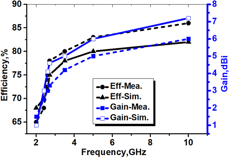
Fig. 13. Simulated (solid curves) and measured (dashed curves) values of the gain and the efficiency of the MIMO antenna.
The CCL characterizes the quality of the MIMO system which can be calculated according to equation (5) [Reference Choukiker, Sharma and Behera19]:
 $${\rm CCL} = -10{\rm lo}{\rm g}_2\; {\rm det}(\rho )$$
where ρ is the correlation matrix of the receiving antenna and can be calculated as:
 $$\eqalign{\rho & = \; \left[ {\; \matrix{ {\rho_{11}} \cr {\rho_{21}} \cr} \; \; \; \; \; \matrix{ {\rho_{12}} \cr {\rho_{22}} \cr}} \right],\,\rho _{ii} = 1-( \vert s_{ii}\vert ^2 + \vert s_{ij}\vert ^2)\,\;{\rm and}\;\rho _{ij} \cr & = (s_{ii}\; s_{ij})^2 + (s_{\,ji}\; s_{ij})^2,\,i,j = 1\; {\rm or}\; 2}$$
Figure 14 presents the measured and simulated CCL values. The dashed curve in Fig. 14 shows that the measured values of the CCL for the proposed sunflower MIMO fractal antenna did not overstep 0.4 b/s/Hz at a lower operating band (2–2.9 GHz) and varied between 0.15 and 0.35 b/s/Hz at a upper operating band (5–10 GHz). Therefore, the sunflower MIMO fractal antenna has low-CCL values that can be used in modern digital communication devices.
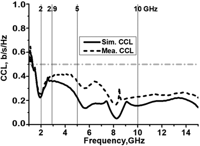
Fig. 14. Simulated and measured CCL for the sunflower MIMO fractal antenna.
The specifications of the MIMO sunflower fractal antenna are better than those of the previous MIMO fractal antennas investigated in [Reference Peristerianos, Argiris, Anastasios and Theodoros3, Reference Rajkumar, Narayanaswamy, Sharada and Krishnasamy8, Reference Saeed Khan, Antonio, Adnan, Raed and Dimitris9, 17, Reference Peristerianos, Argiris, Anastasios, Theodoros and Katherine18, Reference Choukiker, Sharma and Behera19, Reference Yang, Li and Yan26, Reference Abed27] due to the following reasons.
(1) None of the previous MIMO fractal antennas with the same size (40 × 50 × 0.8 mm3) can support 3G, LTE (4G), WLAN (IEEE 802.11n and IEEE 802.11ac), WiMAX (IEEE 802.16), and 5G (5–6 GHz) communication networks.
(2) The mutual coupling between the antennas reduced 20 dB by inserting a strip line into the outer edges of the ground plate.
(3) None of the previous MIMO antennas with the same size (40 × 50 × 0.8 mm3) have the same mutual coupling (from −45 to −25 dB), CCL (0.15–0.4 b/s/Hz), efficiency (65–85%), and gain (1–6 dBi).
(4) The MIMO sunflower fractal antenna exhibits a novel design with a low profile etched on a low-cost and commercial FR-4 substrate.
Conclusion
This work designed a novel MIMO fractal antenna that can support many modern wireless communication applications, such as: 3G, LTE (2.6 GHz), WLAN (IEEE 802.11n and IEEE 802.11ac), WiMAX (2.4 GHz/5 GHz), ISM (2.4 GHz/5 GHz), and 5G (5–6 GHz). Furthermore, the MIMO sunflower fractal antenna has low-mutual coupling, low-CCL, acceptable values of gain and efficiency, and small size. The characteristics of the designed antenna make it suitable for many communication portable devices.
Acknowledgement
Special thanks to Mr. Omar Almukhtar T. Najim, Communication Engineering Depart., Al-Ma'moon University College and Centre of Advanced Electronic and Communication Engineering, (UKM), Malaysia.
 Amer Tawfeeq Abed received a degree in Electrical Engineering from College of Engineering, University of Baghdad, 1984. He has obtained his master's in Communication Engineering from University of TENAGA, Malaysia and his Ph.D. from UKM, Malaysia. He has wide experience in designing the RF circuit and antennas. Dr. Abed has published 25 papers in ISI journals and 2 books about antenna design. He has reviewed more than 30 articles in IET and IEEE journals. Dr. Abed is a member of the European Microwave Association (EMA) and IEEE. Currently, he is a lecturer in Communication Engineering Department, Al-M'mamon University College, Baghdad-Iraq.


