


Introduction
In a cost-effective high-volume integrated circuit (IC) manufacturing facility, the majority of the tasks are completely automated. To bring a (packaged) IC from one station to the next, pick and place handlers using suction are often utilized. These handlers typically are embedded in a system which can be used to test and verify the functionality of the IC [Reference Baba1]. One of the current trends in the IC development is the integration of antennas on-chip or in the package of the IC [Reference Lamminen, Saily and Vimpari2–Reference Park and Wong9]. This poses challenges in the production testing process of the packaged IC, as the antenna functionality has to be included. The characterization of these integrated antennas is challenging as they usually do not provide a suitable direct interface for the measurement equipment [Reference Reniers, van Dommele and Smolders10]. Adding a separate interface to connect the antenna to the measurement system results in additional complexity and associated costs, which is not desired for high-volume production and testing.
In [Reference Heidrich and Wiesbeck11], a method is introduced with which the input reflection coefficient, among other parameters, of an unknown and possibly integrated antenna can be measured in a contactless manner. To do this type of over-the-air (OTA) measurement, an extensive calibration procedure is required. Performing a calibration results in down-time of the measurement system, hence requiring calibration is disadvantageous for high-volume testing. In [Reference Johannsen, Spirito and Smolders12–Reference van den Biggelaar, Daverveld, Reniers, Johannsen and Smolders16], a similar contactless method has been used. With this method, only the reflection coefficient of the antenna can be determined, but no calibration procedure is required.
In [Reference Johannsen, Spirito and Smolders12–Reference Monsalve, Blanch and Romeu15], the measurements were performed in an anechoic chamber. Anechoic chambers suited for high-frequency RF measurements are expensive and the used absorbers typically are covered by carbon dust. ICs are usually manufactured in a clean room, making the use of common RF absorbers in an IC testing facility not practical, if not impossible. It is experimentally verified in [Reference van den Biggelaar, Daverveld, Reniers, Johannsen and Smolders16], that the use of an anechoic chamber is not a necessity to acquire accurate results using this contactless characterization method (CCM), making this CCM attractive for high-volume testing.
In [Reference Johannsen, Spirito and Smolders12–Reference van den Biggelaar, Daverveld, Reniers, Johannsen and Smolders16], the reported separation between the measurement antenna and the antenna-under-test (AUT) has always been larger than the far-field distances of either antenna. However, reducing the separation between the antennas will potentially relief dynamic range requirements of measurement equipment and would allow for more compact testing solutions. Traditionally, pick and place handling systems are not equipped with an OTA testing functionality, but with the upcoming trend of integrating the antenna with the IC, it might even be beneficial that such testing functionality will be included in a pick and place handler. For instance, an RF probe could be embedded in the pick and place handler, combining both the RF testing and pick and place functionality. The concept of such a novel probe is shown in Fig. 1 and is patented in [Reference Johannsen, Reniers and van den Biggelaar17].

Fig. 1. Concept of a probe combining the RF testing and the pick and place functionality.
In this paper, the concept of using the CCM in combination with the probe illustrated in Fig. 1 is assessed from an RF point of view. It is investigated for the first time whether the CCM can be used under near-field conditions, since this will enable compact testing solutions and potentially relief dynamic range requirements. In this case, coupling between the RF probe and the AUT is inevitable. Hence, the sensitivity of the CCM due to the position and alignment errors of the probe is examined. To perform this assessment, positional tolerances of cost-effective commercial available pick and place handlers are used. The effect of vibrations in the measurement system is also examined. To generalize the obtained results, the assessment is performed on three different integrated antenna structures. Moreover, measurement results around 33 GHz using a connectorized patch antenna are shown, which experimentally verify the validity of using the CCM under near-field conditions at millimeter-wave frequencies.
The paper is structured as follows. In Section “The contactless characterization method,” the CCM is briefly explained. Section “Sensitivity of the CCM under near-field conditions” is devoted to modeling the characterization method and adding imperfections in the measurement setup. In Section “Experimental verification,” the measurement setup and results are shown. In Section “Conclusion and future work,” the conclusion and future work is presented.
The contactless characterization method
In Fig. 2, a schematic of the measurement setup of the CCM is shown. A reference antenna (RA) is connected to an uncalibrated vector network analyzer (VNA) and is used to illuminate the AUT. The VNA will measure all waves that are reflected back to the VNA. Examples of these contributions are the impedance mismatch of the RA, reflections due to reflective surfaces of the measurement environment and AUT, and a reflection at the port of the AUT. The key aspect of the CCM is that if a different load is connected to the AUT, this will only affect the latter reflection. By performing three measurements with three different known loads connected to the AUT, the reflection coefficient of the AUT can be retrieved, as shown in [Reference Johannsen, Spirito and Smolders12–Reference van den Biggelaar, Daverveld, Reniers, Johannsen and Smolders16]. Typically, the three different known loads are a short, open, and a load having an impedance equal to the characteristic impedance of the system.

Fig. 2. Schematic of the measurement setup.
Sensitivity of the CCM under near-field conditions
Setup of the CST model
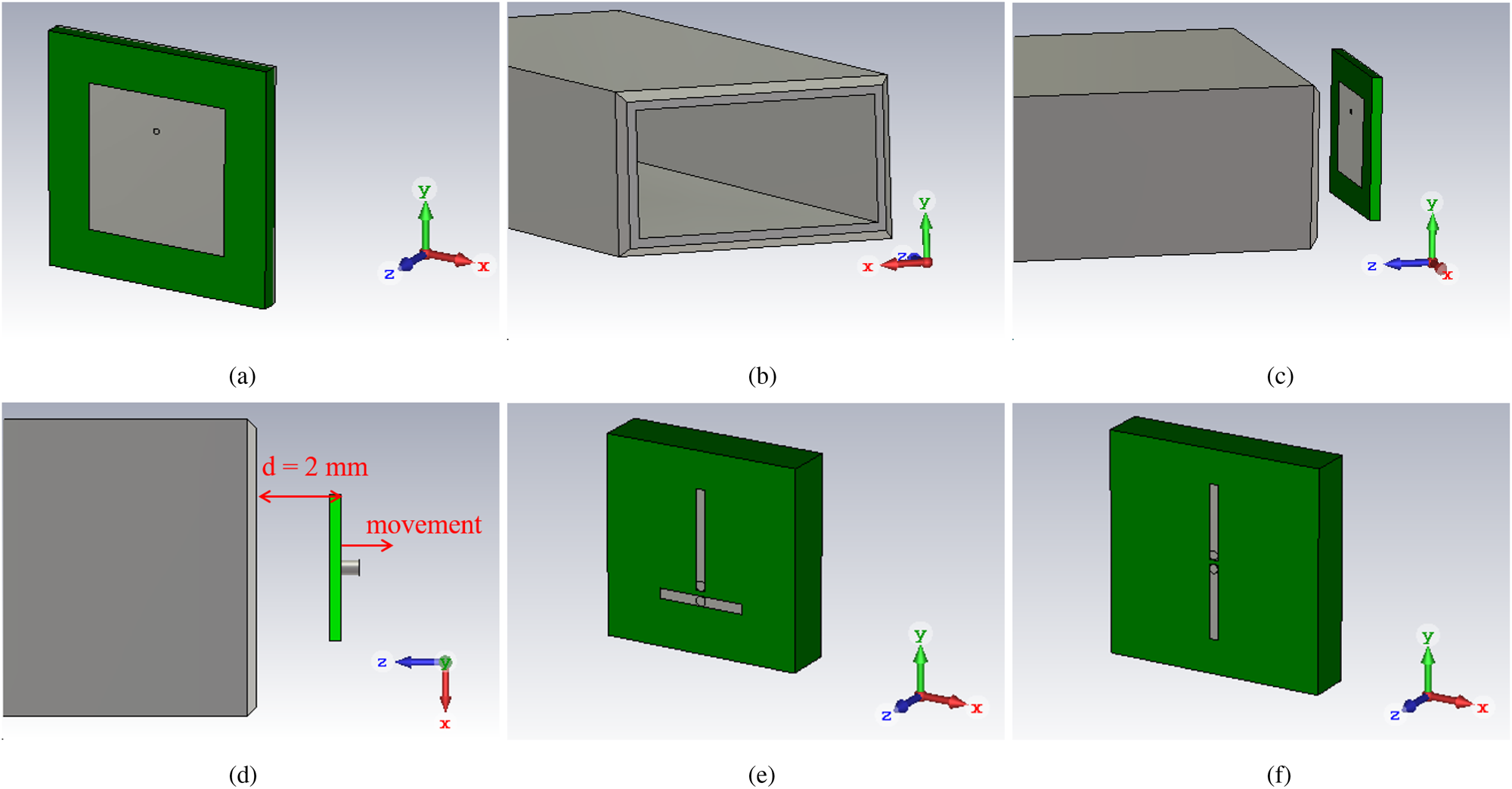
To assess the sensitivity of the CCM under near-field conditions, a full-wave electromagnetic model has been made using CST Microwave Studio. In first instance, a patch antenna has been used as AUT. Mainly because of its planar low-profile structure, this type of antenna is widely used in integrated antenna studies (see for instance [Reference Lamminen, Saily and Vimpari2–Reference Shamim, Arsalan, Roy and Salama8]) and, therefore, a straightforward choice as a starting point for this assessment. In Fig. 3(a), a model of the via-fed patch is shown. The patch is square and its length and width are 2.5 mm. The relative permittivity and loss tangent of the substrate is 3 and 0.025, respectively. The length, width, and thickness of the substrate is 4, 4, and 0.3 mm, respectively. Without loss of generality and to reduce computation time, the patch, ground plane, and feed are made of perfect electric conducting (PEC) material, and the patch and ground plane are given zero thickness. In order to get a well-matched antenna at f c = 32 GHz, the position of the via is 0.65 mm out of the center of the patch.

Fig. 3. CST models showing the (a) patch antenna, (b) OEWG, (c) CCM setup, (d) CCM setup mimicking vibrations, (e) monopole antenna, and (f) dipole antenna.
A WR-28 open-ended waveguide (OEWG) is chosen as RA. The CST model of the OEWG is depicted in Fig. 3(b). The wall thickness is chosen to be 0.5 mm, and the OEWG is modeled using PEC material as well.
The combination of AUT and RA is shown in Fig. 3(c). The centers of both antennas are aligned and the nominal distance between the two antennas is chosen to be 2 mm.
Distance between the AUT and RA
The CCM relies on OTA transmission, which can result in large free-space path loss (FSPL). The signal of interest travels twice the distance between the AUT and RA. If far-field conditions are achieved, this means that every doubling in distance results in 12 dB additional FSPL. Therefore, the distance between the AUT and RA has a significant impact on the required dynamic range of the measurement setup. Since the intended application is a cost-effective high-volume testing procedure, it is advantageous to have a method that does not require the test equipment to have a large dynamic range. Moreover, if losses such as the FSPL are reduced, the intermediate-frequency bandwidth of the VNA can be increased, allowing reduced measurement times.
In [Reference Johannsen, Spirito and Smolders12–Reference Monsalve, Blanch and Romeu15], the reported separation between the AUT and RA has always been larger than the far-field distances of either antenna. However, as shown in this section, it is possible to place the antennas in each other's near-field region and the reflection coefficient can still be accurately determined using the CCM.
The far-field of the used patch at its center frequency of 32 GHz is given byFootnote 1

where D AUT is the diagonal of the square patch, and λc is the wavelength in free-space at the center frequency of 32 GHz. The diagonal D RA of the WR-28 OEWG is 7.95 mm, meaning that the far-field of the used RA at the center frequency of the patch is as follows:

The magnitude of the input reflection coefficient of the patch in a free-space environment is shown in Fig. 4 and is denoted by “Reference.” Additionally, the determined reflection coefficient using the CCM is shown for a separation of the patch and OEWG of 1, 2, and 3 mm. By putting the antennas close to one another, the reflection coefficient of the antennas will be altered due to reflections of both antennas. The discrepancies shown in Fig. 4 are due to this effect. Although the AUT and RA are close, Fig. 4 shows that the effect of the OEWG on the patch is small, hence, the error introduced by putting the antennas in each other's near-field region is small for this setup.

Fig. 4. Determined reflection coefficient for different distances between the patch and OEWG.
In Fig. 4 and subsequent figures, a gray area is used to highlight a tolerable error introduced by the setup. This tolerable error is in this paper defined by $\pm 10\percnt$ of the accepted power of the reference, which is proportional to $\lpar 1-\vert S^{ref}_{11}\vert ^2\rpar$
 , with $S^{ref}_{11}$
 being the reflection coefficient of the patch in the free-space environment depicted in Fig. 3(a).
Sensitivity to positioning errors
In the previous subsection, the centers of the patch and OEWG were perfectly aligned. It is likely, however, that in a high-volume testing facility, most of the samples will not be perfectly aligned to the RA. Therefore, the sensitivity to positioning errors has been assessed. For this assessment, the patch has been translated, mimicking positioning errors, whereas the OEWG remains at its position. The translations Δd x and Δd y are in the positive x- and y-directions, respectively.
In Fig. 5, the results for translations are shown. The translations of 100 μm are based on tolerances of commercial available pick and place handlers. It can be seen that the positioning errors lead to small differences in input reflection coefficient. Both curves of the translation errors remain within the 10% error margin over the entire frequency band. Also here, the discrepancies shown in Fig. 5 are caused by the OEWG which alters the characteristics of the patch.

Fig. 5. Determined reflection coefficient for alignment errors.
Sensitivity to a dynamic setup
For the CCM, three measurements are required, each with a different termination connected to the AUT. In the previous subsections, the setup has been assumed static. However, it could be that during the three measurements, the measurement setup slightly changes. To assess the sensitivity of the CCM to environmental changes, the effect of a vibration in the system is mimicked. In the first simulation, a short is connected to the patch and the distance between patch and OEWG is 2 mm. In the second and third simulation, the patch has been terminated to an open and 50 Ω load, and the distance between patch and OEWG has been increased by Δd v and 2Δd v, respectively. The simulation setup and the movement of the patch are depicted in Fig. 3(d). In Fig. 6, the results are shown for Δd v = 100 μm, Δd v = 10 μm, and Δd v = 1 μm. A deviation of Δd v = 100 μm clearly leads to incorrect results. An error of Δd v = 10 μm leads to better results, but even for this small deviation, the results are not bounded by the 10% error margin region, as can be seen at the edges of the graph. Only when the error is as small as Δd v = 1 μm, accurate results can be achieved and the determined reflection coefficient remains within the 10% error margin region. Hence, it is important to mitigate any vibration in the measurement setup when performing the CCM.

Fig. 6. Determined reflection coefficient for vibrations.
Integrated monopole and dipole antenna
To observe whether the obtained results can also be acquired using antennas different from a patch, two other antenna structures have been assessed. For this assessment, a monopole and dipole antenna are selected since these structures are found in multiple studies on integrated antennas [Reference Chen, Liu, Smolders, Baltus and Gao6–Reference Park and Wong9]. In Figs 3(e) and 3(f), a CST model of the used planar monopole and dipole antenna are shown, respectively. The monopole antenna consists of an arm with a length of 2 mm and a ground with a length of 1.75 mm, in order to have the center frequency around 32 GHz. To have the dipole well-matched to 32 GHz, both arms of the dipole have a length of 1.73 mm. The width of the metal strips of both antennas is 0.1 mm, and the gap between the metal strips is 0.15 mm. The relative permittivity and loss tangent are the same as for the patch. The length, width, and thickness of the substrate of the monopole is 4, 4, and 1 mm, and 5, 5, and 1 mm of the dipole. To reduce computation time, all metals are PEC, and the antennas are given zero thickness. The far-field distances of the monopole and dipole at 32 GHz are 1.26 and 2.76 mm, respectively.
In Fig. 7, the reflection coefficient of the monopole in free space is shown and denoted by “Reference.” Moreover, the determined reflection coefficient of the monopole in a CCM configuration is shown for different separations between the OEWG and monopole. It can be see that for a separation of 1 mm, the OEWG affects the monopole and the determined reflection coefficient of the monopole is not bounded by the 10% error margin. For a separation of 3, 4, or 5 mm, the OEWG hardly affects the monopole and the determined reflection coefficients are bounded by the 10% error margin, as can be seen in Fig. 7. Although a separation of 3 mm is larger than the far-field of the monopole, the monopole is still well within the near-field of the OEWG.

Fig. 7. Determined reflection coefficient for different distances between the monopole and OEWG.
The results while using a dipole antenna as AUT are shown in Fig. 8. Also here, a separation of the OEWG and dipole of only 1 mm detunes the dipole. When the distance between the OEWG and dipole is 3, 4, or 5 mm, it can be seen in Fig. 8 that the effect of the OEWG on the dipole is negligible and the determined reflection coefficients are bounded by the 10% error margin. Also in this case, the separation of 3 mm is larger than the far-field of the dipole, but the dipole is still well within the near-field of the OEWG.

Fig. 8. Determined reflection coefficient for different distances between the dipole and OEWG.
The sensitivity of the CCM to alignment errors and vibrations while characterizing the monopole and dipole is also examined. Similar results as shown in Figs 5 and 6 were acquired. For both the monopole and dipole, an alignment error in the order of 100 μm shows very little deviation, and the determined reflection coefficient stays within the 10% error margin. A vibration in the order of 10–100 μm in the setup leads to incorrect results. When the vibration is limited to 1 μm, the reflection coefficient does not exceed the 10% error margin. To prevent repetition of results, the graphs showing the impact of alignment errors and vibrations on the monopole and dipole have been omitted in the paper.
Experimental verification
In order to verify the simulation results, two different types of measurements have been performed. In the first measurement, the AUT has been directly connected to a calibrated VNA and its reflection coefficient has been measured. In Fig. 9(a), the AUT and the reference plane of the measurement is shown. This measurement serves as a reference. The AUT is an inset-fed square patch antenna with an edge length of 2.3 mm and is placed on top of a 508 μm thick RO4003C substrate. The patch is matched at 33 GHz, and the far-field at that frequency is 2.32 mm. In the second type of measurement, the CCM is performed. The measurement setup for the CCM is shown in Fig. 9(b). Because no switch up to 37 GHz was available at the measurement facility, the loads required for the three measurements had to be changed manually. To minimize vibrations or dislocations caused by manually changing the loads, the AUT was fixated to a stiff metal base. The OEWG is connected to an uncalibrated VNA and three measurements are performed, each with a different termination connected to the AUT. For each set of three measurements, the position of the OEWG was varied to mimic positioning errors.

Fig. 9. Setup for (a) the directly connected reference measurement and (b) the CCM.
In Fig. 10, the measurement results are shown. It can be seen that the five curves, which are determined using the CCM, follow the reference well and all five curves are within the 10% error bounds. Some discrepancies can be found, however. First of all, although the AUT is fixated and the terminations were changed with care, it is not guaranteed that the AUT does not change its position slightly in between the measurements. Second, manually changing the loads requires some time, allowing the measurement setup to slightly drift. If this method will be performed using integrated antennas with onboard terminations, both effects will be mitigated. At last, the OEWG does detune the AUT by being in close proximity. Hence, using the CCM under near-field conditions yields a trade-off between accuracy of the measurement and the dynamic range required by the system.

Fig. 10. Experimentally determined reflection coefficient for different positions of the AUT, relative to the OEWG.
Conclusion and future work
In this paper, the practicality of a CCM is presented, having the application of a cost-effective high-volume testing procedure for integrated antennas in mind. This method can be used to determine the input reflection coefficient of an unknown, and possibly integrated, antenna using OTA measurements under near-field conditions. Using simulations, it is shown that an RA can be positioned in the near-field of the integrated antenna if the AUT is a patch antenna. If the AUT is a dipole or monopole, the distance between the OEWG and AUT has to be increased, but the AUT can still be positioned in the near-field of the OEWG, reducing the FSPL significantly. This will potentially relief dynamic range requirements of measurement equipment and allows for reduced measurement times. Furthermore, it is shown that the impact of positioning errors are not severe, as long as the setup is stationary throughout all three measurements, which are required for the CCM. However, if the setup is not stationary in between measurements due to, for instance, vibrations, the 10% error bounds are exceeded when the displacement is in the order of 10 μm or higher. If the vibrations are limited to 1 μm, accurate results can be achieved. Moreover, results around 33 GHz using a connectorized patch antenna are shown, which experimentally verify the validity of using the CCM under near-field conditions.
Regarding future work, the assessment has been limited to only three types of antennas. To generalize the conclusions drawn in this paper, this assessment has to be performed on other antenna types as well. Moreover, since the intended application is a testing procedure for integrated antennas, the method has to be verified using integrated antennas. In order to do this, the three different terminations and a switch have to be implemented on the IC. In the presented work, perfect knowledge on the reflection coefficient of the three terminations, required for the CCM, is assumed. However, if the terminations are incorporated on-chip, it is not possible to measure the impedance of these terminations. A designer is in this case dependent on the manufacturing process and its associated tolerances. This give rise to an uncertainty in reflection coefficient of the termination and, in turn, an uncertainty in the resulting reflection coefficient of the AUT. In the future, this uncertainty has to be included in measurement results.
Acknowledgments
The authors would like to thank NXP Semiconductors for their support and funding, which made this research possible.
 A.J. (Teun) van den Biggelaar received his M.Sc. degree in Electrical Engineering (with distinction) from the Eindhoven University of Technology (TU/e), the Netherlands, in 2016. His MSc thesis was selected as the best M.Sc. thesis of the Department of Electrical Engineering in the year 2016. He is currently pursuing his Ph.D. degree at the TU/e in Electrical Engineering, with the focus on antenna array calibration and over-the-air measurement techniques for millimeter-wave 5G systems.
 D.P.P. (Daan) Daverveld received his B.Sc. degree in Electrical Engineering from the Eindhoven University of Technology (TU/e), the Netherlands, in 2019. He is currently pursuing his M.Sc. degree at the TU/e in Electrical Engineering, within the Electromagnetics group with focus on telecommunication systems.
 A.C.F. (Ad) Reniers has a bachelor degree in Electrical Engineering and is currently pursuing his Ph.D. degree at the Eindhoven University of Technology, Eindhoven, the Netherlands. His Ph.D. dissertation is entitled: “Uncertainties in millimeter-wave antenna design and characterization.” From 1999 to 2009, he worked with TNO Industry and Technique in Eindhoven, the Netherlands, on research projects, affiliated to antenna-based sensors, antenna miniaturization, RFID applications, and energy harvesting. Since 2009, he has been associated with the Electromagnetics Group, Department of Electrical Engineering, Eindhoven University of Technology, Eindhoven, the Netherlands. He has extensive engineering and research experience in the field of antenna design and antenna measurement. He contributes to various research projects related to, for instance, over-the-air testing. His research interests include uncertainties in millimeter-wave antenna measurements and dielectric material characterization.
 A.B. (Bart) Smolders is the Dean of the Department of Electrical Engineering at the Eindhoven University of Technology (TU/e). Next to this, he is a Full Professor and Chair of the Electromagnetics (EM) group. His key areas of expertise include telecommunication engineering, antenna systems, and microwave engineering. In the EM research group, Smolders’ main focus is on advanced integrated antenna systems and related applications such as phased-arrays and focal-plane arrays for future wireless communications. Bart's team is collaborating on a number of European and national projects, including SILIKA (Silicon-based Ka-band massive MIMO antenna systems for new telecommunication services), EAST (tunable antenna concepts for 5G mobile), Integrant (90 GHz wireless point-to-point systems), MUSIC (60 GHz single-chip MIMO radar), and SMART-One (millimeter-wave channel sounding).
 U. (Ulf) Johannsen received his Dipl.-Ing. degree in Communications Engineering from the Hamburg University of Technology (TUHH, Germany) in 2009. In 2013, he obtained his Ph.D. in electrical engineering from the Eindhoven University of Technology (TU/e, the Netherlands). He then started as Senior Systems Engineer at ATLAS ELEKTRONIK GmbH (Bremen, Germany), where he worked as system designer and engineering manager on autonomous underwater vehicle (AUV) systems with sonar payloads. In 2016, he was appointed Assistant Professor with the Electromagnetics group at the TU/e department of Electrical Engineering. Ulf Johannsen is chair person of the IEEE Benelux joint AP/MTT chapter.


 Open access