


1 Introduction
Controlling a high-energy pulse duration toward its fundamental limit of a single laser cycle ( ${\tau}_{\mathrm{p}}\sim 2.5$
fs) will offer a great advantage in studying the most efficient production of laser-driven processes within a wide range of short-pulse relativistic intensity laser–plasma interactions[
Reference Wheeler, Mourou and Tajima1] including particle acceleration[
Reference Zhou, Yan, Mourou, Wheeler, Bin, Schreiber and Tajima2] and the production of attosecond extreme ultraviolet (XUV) pulses[
Reference Naumova, Nees, Sokolov, Hou and Mourou3]. The post-compression through nonlinear spectral broadening has been a widely used method for achieving single-cycle pulses for many years but has proven more difficult to achieve in the highest energy, Joule-level laser systems until recent years[
Reference Brabec and Krausz4–
Reference Rolland and Corkum7]. The thin-film compressor (TFC), also referred to as compression after compression (CAFCA), is an efficient method for controlling the pulse duration (
${\tau}_{\mathrm{p}}\sim 2.5$
fs) will offer a great advantage in studying the most efficient production of laser-driven processes within a wide range of short-pulse relativistic intensity laser–plasma interactions[
Reference Wheeler, Mourou and Tajima1] including particle acceleration[
Reference Zhou, Yan, Mourou, Wheeler, Bin, Schreiber and Tajima2] and the production of attosecond extreme ultraviolet (XUV) pulses[
Reference Naumova, Nees, Sokolov, Hou and Mourou3]. The post-compression through nonlinear spectral broadening has been a widely used method for achieving single-cycle pulses for many years but has proven more difficult to achieve in the highest energy, Joule-level laser systems until recent years[
Reference Brabec and Krausz4–
Reference Rolland and Corkum7]. The thin-film compressor (TFC), also referred to as compression after compression (CAFCA), is an efficient method for controlling the pulse duration ( ${\tau}_{\mathrm{p}}$
) of a multi-Joule, femtosecond pulsed laser[
Reference Chvykov, Radier, Chériaux, Kalinchenko, Yanovsky and Mourou8–
Reference Khazanov, Mironov and Mourou10]. Figure 1(a) gives a simple sketch of the concept. To first increase the spectral bandwidth of the pulse, a sufficient quantity of thin-film materials as determined by their nonlinear properties for self-phase modulation (SPM) are placed within the freely propagating full aperture beam with uniform top-hat intensity of the order of 1 TW/cm2.
${\tau}_{\mathrm{p}}$
) of a multi-Joule, femtosecond pulsed laser[
Reference Chvykov, Radier, Chériaux, Kalinchenko, Yanovsky and Mourou8–
Reference Khazanov, Mironov and Mourou10]. Figure 1(a) gives a simple sketch of the concept. To first increase the spectral bandwidth of the pulse, a sufficient quantity of thin-film materials as determined by their nonlinear properties for self-phase modulation (SPM) are placed within the freely propagating full aperture beam with uniform top-hat intensity of the order of 1 TW/cm2.

Figure 1 (a) Concept of post-compression with the thin-film compressor (TFC) with spectral broadening occurring due to self-phase modulation (SPM) within the thin films followed by re-compression on the resulting chirped pulse through appropriate dispersion management (DM). (b) Pulse spectra starting from a 14 J pulse initially at 22 fs duration (gray) compared with the subsequent spectrally broadened spectrum (blue) that supports a 9-fs pulse duration after DM that provides compensation for the group delay dispersion of –70 fs2 (green). (c) Pulse average intensity across the beam profile for the original input pulse (gray), the chirped pulse that exits the thin films (red dotted), and the compensated pulse (blue).
Subsequent dispersion management (DM) through technology such as negative dispersion chirped mirrors then re-compresses the pulse to the desired shortened duration. This compression technique has been studied at the TW scale[
Reference Ginzburg, Yakovlev, Zuev, Korobeynikova, Kochetkov, Kuz’min, Mironov, Shaykin, Shaykin and Khazanov11, Reference Mironov, Wheeler, Gonin, Cojocaru, Ungureanu, Banici, Serbanescu, Dabu, Mourou and Khazanov12] demonstrating up to five-fold pulse compression[
Reference Ginzburg, Yakovlev, Zuev, Korobeynikova, Kochetkov, Kuzmin, Mironov, Shaykin, Shaikin, Khazanov and Mourou13] and work is now implementing the method on PW-scale laser systems[
Reference Ginzburg, Yakovlev, Kochetkov, Kuzmin, Mironov, Shaikin, Shaykin and Khazanov14]. The low energy losses permit the option to employ multiple stages to decrease the pulse to the desired duration[
Reference Ginzburg, Yakovlev, Zuev, Korobeynikova, Kochetkov, Kuzmin, Mironov, Shaikin, Shaykin and Khazanov15]. This article describes early development implementing a TFC on the APOLLON 1-PW laser system. The potential control of the number of optical cycles within the pulse of the laser system from a typical initial value of $\sim$
10 cycles (
$\sim$
10 cycles ( ${\tau}_{\mathrm{p}}\sim 25$
fs at
${\tau}_{\mathrm{p}}\sim 25$
fs at ${\lambda}_0=800$
nm) toward the single-cycle limit while minimizing the energy loss offers an important tool for optimizing short-pulse, relativistic intensity interactions.
${\lambda}_0=800$
nm) toward the single-cycle limit while minimizing the energy loss offers an important tool for optimizing short-pulse, relativistic intensity interactions.
The degree of bandwidth generated is linearly proportional to the B-integral $\left({B}_{\mathrm{int}}\right)$
accumulated over the interaction length (
$\left({B}_{\mathrm{int}}\right)$
accumulated over the interaction length ( ${L}_{\mathrm{i}}$
) while the high-intensity pulse (
${L}_{\mathrm{i}}$
) while the high-intensity pulse ( $I\left(r,t,z\right)$
) propagates through the film:
$I\left(r,t,z\right)$
) propagates through the film:
 $$\begin{align}{B}_{\mathrm{i}\mathrm{nt}}={k}_0{n}_2{\int}_0^{L_{\mathrm{i}}}I\left(r,t,z\right)\kern0.1em {\rm d}z\sim {k}_0{n}_2{L}_{\mathrm{i}}{I}_{\mathrm{o}}.\end{align}$$
Here, ${k}_0$
is the standard wavenumber of the laser pulse,
${k}_0$
is the standard wavenumber of the laser pulse, ${n}_2$
is the nonlinear refractive index (
${n}_2$
is the nonlinear refractive index ( $n={n}_0+{n}_2\;I(t)$
) of the film material related to the material’s third-order nonlinear susceptibility,
$n={n}_0+{n}_2\;I(t)$
) of the film material related to the material’s third-order nonlinear susceptibility, ${n}_2=3{\chi}^{(3)}/\left(4{\varepsilon}_0\kern0.1em c\kern0.1em {n}_0^2\right)$
, and
${n}_2=3{\chi}^{(3)}/\left(4{\varepsilon}_0\kern0.1em c\kern0.1em {n}_0^2\right)$
, and ${I}_{\mathrm{o}}$
is the peak pulse intensity.
${I}_{\mathrm{o}}$
is the peak pulse intensity.
The ratio of the broadened spectrum to the spectrum of the input pulse is ${F}_{\omega}=\Delta {\omega}_{\mathrm{out}}/\Delta {\omega}_{\mathrm{in}}$
. Estimates on the expected broadening have been made through simulations by fitting a linear relation to the
${F}_{\omega}=\Delta {\omega}_{\mathrm{out}}/\Delta {\omega}_{\mathrm{in}}$
. Estimates on the expected broadening have been made through simulations by fitting a linear relation to the ${B}_{\mathrm{int}}$
while taking into account the thin-film material group velocity dispersion (
${B}_{\mathrm{int}}$
while taking into account the thin-film material group velocity dispersion ( ${k}_2$
) which generally diminishes the nonlinear response as the pulse energy becomes stretched in time under the typical condition for most materials of positive dispersion (
${k}_2$
) which generally diminishes the nonlinear response as the pulse energy becomes stretched in time under the typical condition for most materials of positive dispersion ( ${k}_2>0$
). The parameter
${k}_2>0$
). The parameter $D={L}_{\mathrm{i}}\;{k}_2/{\tau}_{\mathrm{p}}^2$
accounts for the dispersion relative to the initial pulse duration. The fit parameters found for the spectral broadening give the following linear relation[
Reference Khazanov, Mironov and Mourou10]:
$D={L}_{\mathrm{i}}\;{k}_2/{\tau}_{\mathrm{p}}^2$
accounts for the dispersion relative to the initial pulse duration. The fit parameters found for the spectral broadening give the following linear relation[
Reference Khazanov, Mironov and Mourou10]:
 $$\begin{align}{F}_{\omega}=1+0.91\;{B}_{\mathrm{int}}\left(1-1.5\sqrt{D}\right).\end{align}$$
This relation is used to compare our expected spectral broadening with what is measured.
An initial 22-fs pulse with 14 J of energy is expected to produce sufficient bandwidth to support a 9-fs pulse after traversing 0.84 μm of a material similar to BK7 glass. The one-dimensional calculation made in PyNLO[
Reference Hult16] shows the expected spectral broadening under these conditions in Figure 1(b). The temporal intensity profile is shown in Figure 1(c) which compares the input profile, the resultant chirped pulse, and the intensity after appropriate compensation of $-70\;{\mathrm{fs}}^2$
to the group delay dispersion (GDD).
$-70\;{\mathrm{fs}}^2$
to the group delay dispersion (GDD).
1.1 Laser
One goal of the APOLLON laser is the generation of 10 PW pulses corresponding to an energy of 150 J and 15 fs duration at a repetition rate of 1 shot/min[
Reference Zou, Le Blanc, Papadopoulos, Cheriaux, Georges, Mennerat, Druon, Lecherbourg, Pellegrina, Ramirez, Giambruno, Freneaux, Leconte, Badarau, Boudenne, Fournet, Valloton, Paillard, Veray, Pina, Monot, Chambaret, Martin, Mathieu, Audebert and Amiranoff17–
Reference Papadopoulos, Ramirez, Genevrier, Ranc, Lebas, Pellegrina, Monot, Martin, Zou, Mathieu, Audebert, Georges and Druon19]. APOLLON will provide this in a combination among up to four beam lines (10 PW, 1 PW, 100 TW, and an uncompressed beam), all generated following the last amplifier from the same beam to allow for different geometry and synchronization configurations when re-combined on the target. This experimental campaign uses the APOLLON 1-PW laser which was originally designed to deliver 15-fs-duration pulses with 15 J of energy for 1 PW at a one shot/min repetition rate and has demonstrated the capacity of generating $>$
1-PW pulses[
Reference Papadopoulos, Zou, Ranc, Druon, Martin, Freneaux, Beluze, Lebas, Chabanis, Bonnin, Accary, Garrec, Mathieu and Audebert20]. The pulse spectrum has a bandwidth of
$>$
1-PW pulses[
Reference Papadopoulos, Zou, Ranc, Druon, Martin, Freneaux, Beluze, Lebas, Chabanis, Bonnin, Accary, Garrec, Mathieu and Audebert20]. The pulse spectrum has a bandwidth of $\sim$
50 nm FWHM (at
$\sim$
50 nm FWHM (at $\sim$
820 nm) under full-power operation. Compression of the full aperture (
$\sim$
820 nm) under full-power operation. Compression of the full aperture ( $\phi =14$
cm) amplified pulses in the 1-PW compressor resulted in the duration of the pulses, after optimization of the dispersion with a DAZZLER, to be 21.5 fs as measured with a WIZZLER device.
$\phi =14$
cm) amplified pulses in the 1-PW compressor resulted in the duration of the pulses, after optimization of the dispersion with a DAZZLER, to be 21.5 fs as measured with a WIZZLER device.
For this commissioning experiment, the pulse energy after the fourth amplifier was kept below the maximum so that the expected final energy deliverable to the interaction target chamber was 14 J. Wedges placed in the beam transport between the amplifier and the compressor can further decrease the pulse energy by 75%, 50%, 30%, 10%, or 1% of the full 14 J energy. The experiment ran the system at the full amplification of the beam (14 J) but attenuated at 50% energy before the compressor for the data presented here to give 7 J within the 14-cm-diameter beam producing a fluence of approximately 45 mJ/cm2. The measured pulse duration using both a Bonsai autocorrelator and WIZZLER for this campaign was 22 fs. This gives a peak intensity of the full diameter beam of approximately 2.2 TW/cm2.
1.2 LFA target chamber
The APOLLON facility offers two experimental areas, with this experiment taking place in the Long Focal Area (LFA) where mostly gas targets and electron acceleration experiments will be realized. Figure 2 shows a sketch of the setup where the thin films of the TFC design are placed near the beam entrance inside the target chamber of the LFA experimental area. The thin films (TF in Figure 2) employed are thin glass wafers (Schott AF32eco) of 0.4 and 0.3 mm
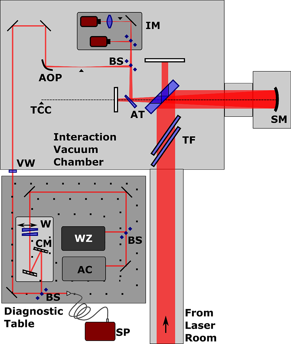
Figure 2 Experimental layout within the Long Focal Area (LFA) of the APOLLON facility. The beam is transported under vacuum from the laser room until exiting the interaction chamber for the adjacent laser diagnostic table. Within the figure, the elements described within the text are labeled by the following acronyms: thin films (TF), spherical mirror (SM), target chamber center (TCC), reflection from uncoated fused silica substrates installed as attenuators (AT), beamsplitters (BS), near-field and far-field beam imaging (IM), off-axis parabola (AOP), vacuum window (VW), wedge pair (W), dispersion, or chirped, mirrors (CM), spectrometer (SP), WIZZLER (WZ), and autocorrelator (AC).
thickness at 30 cm diameter installed at an angle of incidence (AOI) near the Brewster’s angle of 56° to minimize losses. The glass wafers are carefully mounted within custom frames manufactured in house at the APOLLON facility. While the use of thin-film polymers has been proposed as ideal for the TFC method, the glass wafers represented readily available, standard stock materials that were pre-approved for vacuum compatibility within the LFA target chamber of the APOLLON laser facility[
Reference Mironov, Ginzburg, Gacheva, Silin, Kochetkov, Mamaev, Shaykin and Khazanov21, Reference Ursescu, Matei, Talposi, Iancu, Aleksandrov, Bleotu, Naziru, Tesileanu, Rosu, Nakamiya, Cernaianu, de Boisdeffre, Ene, Caragea, Lazar, Kiss, Masruri, Caratas, Toader, Nistor, Luta, Tatulea, Popa, Stan, Jitsuno, Banici, Baleanu, Gradinariu, Wheeler, Mourou and Dancus22]. The best examples of transmitted wavefront error for these standard wafers are on the order of (1.4 ± 0.2) $\lambda$
for the 0.4 mm wafer and (1.0 ± 0.2)
$\lambda$
for the 0.4 mm wafer and (1.0 ± 0.2) $\lambda$
for the 0.3 mm wafer (at wavelength of 633 nm) as measured in the facility’s optics metrology laboratory. It was necessary to test several samples before finding examples that were at this level. To the best of the authors’ knowledge, the nonlinear optical properties for Schott AF32eco glass are not reported, but as it is a borosilicate glass, the values for the nonlinearity and dispersion are assumed similar to those of Schott BK7 glass, i.e.,
$\lambda$
for the 0.3 mm wafer (at wavelength of 633 nm) as measured in the facility’s optics metrology laboratory. It was necessary to test several samples before finding examples that were at this level. To the best of the authors’ knowledge, the nonlinear optical properties for Schott AF32eco glass are not reported, but as it is a borosilicate glass, the values for the nonlinearity and dispersion are assumed similar to those of Schott BK7 glass, i.e., ${n}_2\sim 1.5\times {10}^{-16}\;{\mathrm{cm}}^2/\mathrm{W}$
and
${n}_2\sim 1.5\times {10}^{-16}\;{\mathrm{cm}}^2/\mathrm{W}$
and ${k}_2\left(800\;\mathrm{nm}\right)\sim 44.7\;{\mathrm{fs}}^2/\mathrm{mm}$
. The thickness of the glass wafers and their angle to the incoming beam yield a total accumulated nonlinear interaction length of
${k}_2\left(800\;\mathrm{nm}\right)\sim 44.7\;{\mathrm{fs}}^2/\mathrm{mm}$
. The thickness of the glass wafers and their angle to the incoming beam yield a total accumulated nonlinear interaction length of ${L}_{\mathrm{i}}\sim 0.84\;\mathrm{mm}$
. Therefore, estimates for the B-integral from Equation (1) give
${L}_{\mathrm{i}}\sim 0.84\;\mathrm{mm}$
. Therefore, estimates for the B-integral from Equation (1) give ${B}_{\mathrm{int}}\sim 1.4$
which along with the dispersion,
${B}_{\mathrm{int}}\sim 1.4$
which along with the dispersion, $D\sim 0.085$
, results in the expected
$D\sim 0.085$
, results in the expected ${F}_{\omega }$
from Equation (2) to be
${F}_{\omega }$
from Equation (2) to be
 $$\begin{align*}{F}_{\omega}=1+0.51\;{B}_{\mathrm{int}}\sim 1.7.\end{align*}$$
The beam then continues to a mirror with a hole that passes a sub-aperture of the beam intended to generate a separate temporally delayed pump or probe beam. The reflection from the mirror directs the primary beam to a spherical mirror (SM) with 3 m focus passing back through the hole and to the target interaction point of the chamber (TCC, equivalence also denoted by ▴ in Figure 2).
The laser focal spot is optimized by a single adaptive-optic closed-loop wavefront control system, employing a deformable mirror with 52 mechanical actuators (ILAO-star, Imagine Optic) installed at the output of the amplification section. The optimization is based on a two-step process, starting with a closed-loop correction before compression followed by a manual optimization of the focal spot measured in parallel to the target focus.
1.3 Diagnostics
The beam is attenuated after interacting with the films by replacing the last mirror before the SM by an uncoated fused silica mirror substrate with an appropriate hole (AT in Figure 2). The reduction is estimated to be a factor of 0.006 for the p-polarized pulse. The silver-coated spherical mirror is left in place while a motorized half silver-coated wedge (FICHOU Optics) placed before the focus permits additional attenuation. The silver-coated half of the wedge is inserted when aligning the experiment with the 10-Hz beam at low energy but is then translated under vacuum to the uncoated half to further attenuate the beam before the diagnostics when the full-energy shots are taken. The beam is directed to a broadband R80/T20 beamsplitter (Thorlabs UFBS 80/20) with the transmitted portion passing to a combination of cameras (IM) in the vacuum that monitor the focus and the near-field at the mirror with a hole immediately after the glass wafers. The portion of the beam reflected from the R80/T20 BS is recollimated after the focus by an off-axis parabola (OAP; f = 100 mm) to approximately a 4.5-mm diameter before exiting the vacuum chamber through a 3-mm-thick CaF2 vacuum window (VW). The laser diagnostic table is located beside the interaction chamber within the LFA experimental area. The spectra are measured after a second R80/T20 BS using a network fiber spectrometer (SP in Figure 2; Ocean Optics JAZ). Measurements outside of vacuum require additional compensation to the SPM process due to the vacuum window, propagation through air, and any other optics introduced within the beam transport (i.e., mirror bounces, beamsplitters, or waveplates). The pulse is reflected from a pair of 25-mm-diameter negative dispersive, or chirped, mirrors (CM in Figure 2; Ultrafast Innovations) that can provide discrete negative GDD correction (HD58; –250 fs2/bounce). Typically, by over-compensating to a negative chirp with the dispersive mirrors, a pair of wedges (W in Figure 2; Thorlabs UFBS 2550) provides variable positive dispersion for finely adjusting the pulse duration before passing to the Bonsai autocorrelator (AC) and the Fastlite WIZZLER (WZ). An estimate of the GDD introduced by the contributions of the various components of the beam transport and DM system is between 600 and 800 fs2 with two bounces on the dispersive mirror pair and depending on the wedge positions.
2 Experimental results
The results of this study are summarized in Figure 3.
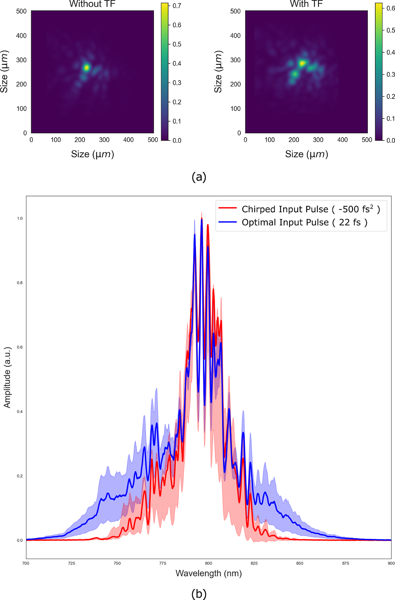
Figure 3 (a) Measured focus images and (b) pulse spectra. In (a), the left image shows the reference focus with no glass films in the beam path and the right image shows the focus after the thin films have been installed. For (b), the red spectrum is the average of two initial shots that result when the input pulse is chirped before entering the glass films and leads to no broadening due to the decrease in the pulse intensity. The blue spectrum shows the average value of 36 shots when the input pulse duration is optimized to 22 fs duration with maximum pulse intensity so that nonlinear spectral broadening occurs in the plate. The red and blue shaded regions represent their respective standard deviations.
The deformable mirror demonstrated correction for some of the aberrations introduced by the thin films, but little time was spent fully controlling the focal spot during this campaign. The energy spread is seen to increase in the images of the focus in Figure 3(a) when comparing the change before and after the glass film insertion. During this campaign, the focus is corrected at low energy after inserting the thin films but no final optimization of the focus at full energy was performed before the end of the time available. Although the suppression of small-scale beam features is a necessary element to control within the nonlinear SPM interaction in order to maintain the best focus[ Reference Voronin, Zheltikov, Ditmire, Rus and Korn23– Reference Farinella, Stanfield, Beier, Nguyen, Hakimi, Tajima, Dollar, Wheeler and Mourou26], the primary goal in controlling the focus quality in this campaign was to ensure that the laser diagnostics can function correctly and that the focus is not modified enough to affect the pulse measurement. It is expected that the deformable mirror is capable of correcting the level of distortion observed in the focus when more time is devoted to its improvement.
The increase in the spectrum after passing through the thin film is demonstrated in Figure 3(b) by comparing the spectra of the optimized pulse duration with that chirped by a second-order dispersion in the phase of –500 fs2 introduced by the laser system’s DAZZLER. The 22-fs pulse chirped by –500 fs2 is expected to be stretched to approximately 67 fs and the peak intensity decreased to the point of no appreciable effect on the original laser spectrum due to SPM. When the pulse duration is optimized to 22 fs, the spectral width is broadened by the SPM process. The pulse duration measured by the autocorrelator is influenced by the configuration of the DM system whose GDD contribution must be considered in the pulse measurement. The negative chirp introduced by the DAZZLER (–500 ${\mathrm{fs}}^2$
) pre-compensates the overall positive dispersion introduced by the DM (
${\mathrm{fs}}^2$
) pre-compensates the overall positive dispersion introduced by the DM ( $\sim$
600 fs2) subsequent to the glass film. In accounting for this, the influence of a 100-fs2 chirp on a pulse of 22 fs corresponds to the pulse duration between 35 and 40 fs as measured by the autocorrelator. Maintaining the pulse duration becomes more sensitive to the optics when the pulse spectrum is broadened through SPM. Here the autocorrelator measured a pulse duration averaging around 150 fs which corresponds to a 15-fs pulse chirped by the 600 fs2 introduced by the DM.
$\sim$
600 fs2) subsequent to the glass film. In accounting for this, the influence of a 100-fs2 chirp on a pulse of 22 fs corresponds to the pulse duration between 35 and 40 fs as measured by the autocorrelator. Maintaining the pulse duration becomes more sensitive to the optics when the pulse spectrum is broadened through SPM. Here the autocorrelator measured a pulse duration averaging around 150 fs which corresponds to a 15-fs pulse chirped by the 600 fs2 introduced by the DM.
The pulse was too chirped to be measured by the WIZZLER under these conditions. The time constraints of the experimental campaign prevented adjustments to the DM system that would have permitted a direct measurement of the shortest pulse duration with the optimal, spectrally broadened pulse. Despite the inability to measure the pulse duration directly, estimates of the value have been made based on the recorded laser parameters and the measured spectra.
The diagnostic shot values for the energy per shot averaged to 6.4 ± 0.2 J so that the fluence average was 41 ± 1 mJ/cm2, and intensity was 1.97 ± 0.05 W/cm2 for a 22 ± 1 fs pulse. Using these values in Equation (1), ${B}_{\mathrm{int}}=1.8$
, and from Equation (2), the spectrum is expected to be broadened by a factor of
${B}_{\mathrm{int}}=1.8$
, and from Equation (2), the spectrum is expected to be broadened by a factor of
 $$\begin{align*}{F}_{\omega}\approx 1+0.51\left({B}_{\mathrm{int}}=1.8\right)\approx 1.9.\end{align*}$$
The largest contribution in this estimation comes from the assumed value of ${n}_2$
.
${n}_2$
.
The average measured spectral bandwidth after interacting with the thin films is 74 ± 2 nm, which corresponds to a pulse duration of approximately 15 fs. This is to be compared with the original input pulse measured with an optimized pulse duration of 22 fs and bandwidth of 41 ± 1 nm. The ratio of these measured pulse spectral bandwidths
 $$\begin{align*}{F}_{\omega}^{\mathrm{meas}}=1.8\pm 0.1\end{align*}$$
is in good agreement with the value estimated for a borosilicate glass of these dimensions interacting with a pulse of this energy and duration. It confirms that the full energy pulse can be delivered at the optimized pulse duration within the interaction chamber and the assumption made for the value of ${n}_2$
for the glass films is reasonable to make estimations of the pulse characterizations be expected when using the full energy in future experiments.
${n}_2$
for the glass films is reasonable to make estimations of the pulse characterizations be expected when using the full energy in future experiments.
3 Conclusions
TFC is of interest to achieve the shortest pulse duration for a high-energy laser system. The APOLLON facility has demonstrated the delivery of 7-J pulses with duration of 21.5 fs by measuring the broadened bandwidth due to the nonlinear SPM response within a series of thin glass plates. Although unable to perform tests at the full energy of the system (14 J) during this campaign, the possibility to increase the energy by a factor of roughly twice that measured during this experimental beam time leads to ${B}_{\mathrm{int}}\sim 3.7$
and an expected spectral broadening of
${B}_{\mathrm{int}}\sim 3.7$
and an expected spectral broadening of ${F}_{\omega}\sim 2.9$
. Therefore, the expected bandwidth after the interaction is
${F}_{\omega}\sim 2.9$
. Therefore, the expected bandwidth after the interaction is $\Delta {\omega}_{\mathrm{out}}\left(\mathrm{FWHM}\right)\sim$
120 nm which supports a sub-10-fs pulse duration. The PyNLO one-dimensional calculations shown in Figure 1 apply the values for the glass wafers and the pulse at 14 J to show both the expected comparison between the spectra and temporal intensities for the input and resultant pulses. In this way, the peak intensity of the pulse across the beam profile is increased from 2.2 to 9.5 TW/cm2.
$\Delta {\omega}_{\mathrm{out}}\left(\mathrm{FWHM}\right)\sim$
120 nm which supports a sub-10-fs pulse duration. The PyNLO one-dimensional calculations shown in Figure 1 apply the values for the glass wafers and the pulse at 14 J to show both the expected comparison between the spectra and temporal intensities for the input and resultant pulses. In this way, the peak intensity of the pulse across the beam profile is increased from 2.2 to 9.5 TW/cm2.
The original design goal for the laser facility of 15 fs has been difficult to achieve due to limitations of mirror technology in transporting such broadband, high-energy pulses. The introduction of TFC can achieve the intended 15 fs (or below) inside the interaction chamber. This minimizes the constraints placed on the beam transport from the grating compressor up to the interaction chamber to more standard high-energy dielectric coatings capable of maintaining a pulse duration greater than 20 fs. The final post-compression step then occurs closer to the intended target thus limiting the specialized ultrashort optics to the final few. This reduces the number required and facilitates replacing these potentially fragile ultra-broadband coated elements more frequently, if needed.
The added flexibility in the control of the post-compression of the pulse permits the optimization in the pulse duration from its initial value eventually down toward the single cycle. The final duration selected will be determined relative to the laser–plasma interaction for the initial energy at a given laser system. As an example, Wu et al. [ Reference Wu, Gong, Shou, Tang, Yu, Mourou and Yan27] recently reported studies on laser-driven ion acceleration in the RPA regime that suggest three- or four-cycle pulses are optimal for 12-J pulses and permit an energy conversion efficiency of over 30%. Similar improvements in laser conversion efficiency with single-cycle pulse drivers are expected for short-pulse X-ray generation[ Reference Naumova, Nees, Sokolov, Hou and Mourou3]. The results of this article show that these conditions are readily attainable at the APOLLON PW beamline and suggest future experimental regimes to be tested when the TFC can be fully implemented with dispersion compensation for the full beam placed within the interaction vacuum system.
Acknowledgment
P.-G.B. and D.U. acknowledge the support in this work provided through the project SBUF (ELI-RO 16/2020).


 Open access