


1 Introduction
X-ray free-electron lasers (FELs)[ Reference Huang and Kim 1 – Reference Yan, Huang, Deng, Liu, Wang and Zhao 3 ], characterized by high brightness, spatial coherence, and ultrashort pulse, represent a revolution in light source development, opening up new frontiers of ultrafast and ultrasmall science in atomic physics, femtochemistry, biology, and so on[ Reference Bostedt, Boutet, Fritz, Huang, Lee, Lemke, Robert and Schlotter 4 – Reference Chapman, Fromme, Barty, White, Kirian, Aquila, Hunter, Schulz, DePonte, Weierstall, Doak, Maia, Martin, Schlichting, Lomb, Coppola, Shoeman, Epp, Hartmann, Rolles, Rudenko, Foucar, Kimmel, Weidenspointner, Holl, Liang, Barthelmess, Caleman, Boutet, Bogan, Krzywinski, Bostedt, Bajt, Gumprecht, Rudek, Erk, Schmidt, Hömke, Reich, Pietschner, Strüder, Hauser, Gorke, Ullrich, Herrmann, Schaller, Schopper, Soltau, Kühnel, Messerschmidt, Bozek, Hau-Riege, Frank, Hampton, Sierra, Starodub, Williams, Hajdu, Timneanu, Seibert, Andreasson, Rocker, Jönsson, Svenda, Stern, Nass, Andritschke, Schröter, Krasniqi, Bott, Schmidt, Wang, Grotjohann, Holton, Barends, Neutze, Marchesini, Fromme, Schorb, Rupp, Adolph, Gorkhover, Andersson, Hirsemann, Potdevin, Graafsma, Nilsson and Spence 6 ]. FELs have been in operation for users with the great success of several operational facilities around the world, such as LCLS, FERMI, FLASH, and SACLA[ Reference Emma, Akre, Arthur, Bionta, Bostedt, Bozek, Brachmann, Bucksbaum, Coffee, Decker, Ding, Dowell, Edstrom, Fisher, Frisch, Gilevich, Hastings, Hays, Hering, Huang, Iverson, Loos, Messerschmidt, Miahnahri, Moeller, Nuhn, Pile, Ratner, Rzepiela, Schultz, Smith, Stefan, Tompkins and Turner 7 – Reference Ishikawa, Aoyagi, Asaka, Asano, Azumi, Bizen, Ego, Fukami, Fukui, Furukawa, Goto, Hanaki, Hara, Hasegawa, Hatsui, Higashiya, Hirono, Hosoda, Ishii, Inagaki, Inubushi, Itoga, Joti, Kago, Kameshima, Kimura, Kirihara, Kiyomichi, Kobayashi, Kondo, Kudo, Maesaka, Maréchal, Masuda, Matsubara, Matsumoto, Matsushita, Matsui, Nagasono, Nariyama, Ohashi, Ohata, Ohshima, Ono, Otake, Saji, Sakurai, Sato, Sawada, Seike, Shirasawa, Sugimoto, Suzuki, Takahashi, Takebe, Takeshita, Tamasaku, Tanaka, Tanaka, Tanaka, Togashi, Togawa, Tokuhisa, Tomizawa, Tono, Wu, Yabashi, Yamaga, Yamashita, Yanagida, Zhang, Shintake, Kitamura and Kumagai 10 ]. However, these FEL facilities based on radiofrequency (RF) technology usually have quite large scales, up to several kilometers, which significantly increases the expense and hinders the way for the wider application of the FEL. It is therefore desirable to dramatically reduce the size and cost of the X-ray FEL to the university–laboratory scale.
Compact FELs driven by laser plasma accelerators (LPAs) have considerable potential to become a table-top light source with smaller scale[ Reference Schroeder, Fawley, Esarey and Leemans 11 – Reference Fuchs, Weingartner, Popp, Major, Becker, Osterhoff, Cortrie, Zeitler, Horlein, Tsakiris, Schramm, Rowlands-Rees, Hooker, Habs, Krausz, Karsch and Gruner 14 ]. The LPA generates an electron beam with energy of a few gigaelectronvolts within a centimeter scale of the accelerating distance[ Reference Tajima and Dawson 15 – Reference Wang, Li, Liu, Zhang, Qi, Yu, Liu, Fang, Qin, Wang, Xu, Wu, Leng, Li and Xu 22 ]. Typical properties of the LPA beam are a peak current of up to tens of kiloamperes, a pulse duration of several femtoseconds, and a normalized transverse emittance below 1 mm·mrad[ Reference Liu, Xia, Wang, Lu, Wang, Deng, Li, Zhang, Liang, Leng, Lu, Wang, Wang, Nakajima, Li and Xu 20 ]. The major problems of the LPA beam for FEL generation are a large initial divergence and a large initial energy spread, drastically increasing the difficulty of the LPA beam transportation from the accelerator to the undulators and causing degradation of the FEL radiation gain.
In the FEL community, several specific methods based on transverse gradient undulators (TGUs), decompression, and coherent harmonic generation (CHG) have been proposed to minimize the energy spread effect, leading to a substantial improvement in FEL gain and radiation power[ Reference Huang, Ding and Schroeder 23 – Reference Liu, Feng, Xiang, Liu and Wang 31 ]. Recently, FEL based on LPA has been lasing successfully at 27 nm paving the way towards the development of compact X-ray FELs[ Reference Wang, Feng, Ke, Yu, Xu, Qi, Chen, Qin, Zhang, Fang, Liu, Jiang, Wang, Wang, Yang, Wu, Leng, Liu, Li and Xu 32 ].
On the other hand, the output characteristics of FEL pulses both in spectral and temporal domains are needed to be adjusted to satisfy some specific experimental requirements. For instance, one of the most important formats is to create two-color FEL pulses which contain two different spectral lines with adjustable time separation. The pump-probe experiments can be accessed by using two-color FEL pulses, opening the door for scientists to study the structural dynamics on the atomic and molecular scale. For conventional RF accelerator-based FEL facilities, several methods of two-color FEL generation have been proposed and demonstrated experimentally[ Reference Ciocci, Dattoli, Pagnutti, Petralia, Sabia, Ottaviani, Ferrario, Villa and Petrillo 33 – Reference Vicario, Bettoni, Lutman, Dax, Huppert and Trisorio 49 ]. Compared with the normal scheme combining a conventional laser pump with an X-ray FEL probe, the most notable advantages are insignificant timing jitter and tunable wavelengths. These methods provide a helpful way to realize the LPA based two-color FEL. The LPA is not only taken into consideration for regular FEL mode generation, but also expected to provide more output characteristics, i.e., two-color pulses.
In this paper, we propose a novel and simple scheme for the generation of the LPA-based two-color X-ray FEL pulses. This proposal makes full use of the large initial divergence and energy spread of the LPA beam that generates time-dependent mismatch with the help of quadrupoles and chicane. Several quadrupoles close to the initial beam induce an energy-dependent mismatch. The following chicane decompresses the beam and energy-dependent mismatch transfers to time-dependent mismatch, meanwhile the large slice energy spread is also reduced. We match different slice Twiss parameters by varying quadrupoles and adjust time separation by varying the delay-time chicane. The detailed description of the working principle and scheme design is given in Section 2 and numerical simulations of beam tracking and FEL process are presented in Section 3. Several issues are discussed and conclusions are given in Section 4.
2 Scheme design
Fresh-slice-based schemes are the most popular and main methods of the two-color FEL generation and have been demonstrated experimentally[ Reference Lutman, Maxwell, MacArthur, Guetg, Berrah, Coffee, Ding, Huang, Marinelli, Moeller and Zemella 36 , Reference Qin, Ding, Lutman and Chao 40 , Reference Chao, Qin, Ding, Lutman and Maxwell 41 , Reference Feng and Deng 47 ]. Usually an auxiliary device, e.g., a dechirper, is required to spoil the beam. For the LPA beam with large divergence and energy spread, we can use quadrupoles and chicane to spoil the beam and generate fresh slices easily. Simultaneously, the slice energy spread would be decreased significantly by the chicane. The layout of the proposed scheme is sketched in Figure 1, including two quadrupole sections, two chicanes, and two planar undulator sections. The details are presented in the following.

Figure 1 Schematic of the proposed scheme for the LPA-based two-color FEL generation. Two quadrupole sections are adopted for matching the bunch tail and head, respectively. The first chicane is used to induce the time-dependent matching, and the second chicane is for time separation of the two-color pulses. Two planar undulator sections are arranged for the two-color FEL generation individually.
-
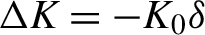
• The quadrupole triplet with high magnetic field gradient is close to the initial LPA beam, which is used to focus the beam and match the Twiss parameter at the undulator entrance position. For the beam with energy deviation $\delta$
, the quadrupole kick deviation is expressed as
$\Delta K=-{K}_0\delta$
with focusing parameter
${K}_0$
and the emittance growth is
$\Delta \varepsilon ={\sigma}_{\delta }{K}_0s{\sigma}_x$
for a beam with energy spread
${\sigma}_{\delta }$
, quadrupole length
$s$
, and beam size
${\sigma}_x$
. Owing to the intrinsic large divergence and energy spread, strong focusing with high gradient
${K}_0$
will induce a significant chromaticity, i.e., energy-dependent mismatch[
Reference Liu, Zhang, Wang and Huang
26
].
$\delta$
, the quadrupole kick deviation is expressed as
$\Delta K=-{K}_0\delta$
with focusing parameter
${K}_0$
and the emittance growth is
$\Delta \varepsilon ={\sigma}_{\delta }{K}_0s{\sigma}_x$
for a beam with energy spread
${\sigma}_{\delta }$
, quadrupole length
$s$
, and beam size
${\sigma}_x$
. Owing to the intrinsic large divergence and energy spread, strong focusing with high gradient
${K}_0$
will induce a significant chromaticity, i.e., energy-dependent mismatch[
Reference Liu, Zhang, Wang and Huang
26
]. -
• The following chicane decompresses the beam, inducing an energy chirp and transferring energy-dependent mismatch to time-dependent mismatch. Meanwhile, it also decreases the slice energy spread being benefit for FEL generation.
-
• By adjusting the triplet and the decompression chicane, we can match the optimal Twiss parameters of the bunch tail to the entrance of the first undulator section. The head part of the bunch is significantly mismatched with respect to the matched lattice setup. Passing through the first undulator section, the bunch tail can lase at resonant wavelength, other than bunch head.
-
• Another four-quad matching section located between the two undulator sections is adopted to match the bunch head and mismatch the bunch tail so that the head part can lase in the second undulator section at different resonant wavelength. In addition to the tail mismatch, the induced large energy spread due to the tail lasing can also suppress the tail lasing in the second undulator effectively.
-
• The second chicane between the two undulator sections can be adjusted for the time separation of the two-color pulses flexibly and wash out the microbunching of the bunch tail generated in the first undulator.


The main parameters of the LPA beam are listed in Table 1. Experimentally, the electron beam with energy in the gigaelectonvolt range, peak current up to 10 kA, and emittance in the range of 0.1–1 mm·mrad has been generated using LPA. The total energy spread is typically of the order of 1%, which usually includes an energy chirp. For the LPA based FEL, due to the femtosecond-level pulse duration comparable to the FEL cooperation length, energy chirp can be neglected and the slice energy spread is also assumed as 1%.
Table 1 Main parameters of an LPA beam.

The LPA beam is focused and the Twiss parameters of the bunch tail are matched from the plasma jet to the undulator entrance using quadrupoles. These three quadrupoles are aligned quite close to the plasma jet with ultra-high magnetic field gradient. After the three quadrupoles, the chromaticity effect induces an energy-dependent mismatch and transfers to time-dependent mismatch due to the following chicane. Passing through the dispersion chicane, time-dependent transverse phase spaces are shown in Figure 2. The time-dependent mismatches are induced both in x and y directions, which is what is required for two-color FEL generation.

Figure 2 Phase space distributions as a function of time downstream of the triplet and decompression chicane. The time-dependent transverse phase spaces show the visible variation along the bunch especially in x and x ′ due to the controlled chromaticity effect. Bunch head is on the left.
According to the scheme layout in Figure 1, lattice design and matching are shown in Figure 3 using an optics tool MAD-8[ Reference Grote and Iselin 50 ]. The first triplet with each quadrupole length of 0.15 m and ultra-high gradient is located extremely close to the plasma jet with distance of 0.1 m. In particular, the first two quadrupoles are up to approximately 200 and 150 T/m, respectively, and the third is relatively normal with about 30 T/m gradient. The decompression chicane with each dipole length of 0.1 m is located at 0.4 m downstream of the triplet. The lower-energy particles will be the tail of the bunch and the higher-energy particles will be the head after the chicane. Two 15-m-long spaces are reserved for the planar undulators (blue), the first starts from 5 m and the second is from 25 m. The four-quad matching section and the second chicane are between the two undulator sections.

Figure 3 Layout of the lattice design and evolutions of beta functions with different beam energy deviations along the transport line. Left: Energy is 1.29 GeV at the bunch tail. Right: Energy is 1.31 GeV at the bunch head. Two undulator sections are located at the 5–20 m range and 25–40 m range, respectively.

Figure 4 Sliced parameters of the LPA beam at the entrance of the first undulator section.
The reference central energy is 1.3 GeV and Figure 3 presents the evolutions of beta functions with energy of 1.29 GeV at the bunch tail part and 1.31 GeV at the bunch head part. Note that the natural focusing of the undulator has been included. Beta functions of 1.29 GeV energy are matched first, and the average beta values of x and y in the first undulator section are smaller than 10 m, whereas the average beta of 1.31 GeV in the x direction in the same range is larger than 50 m. Therefore, the FEL gain length for 1.29 GeV is much smaller than the head one for 1.31 GeV in the first undulator section. The much higher power generated from the tail part than the head part is expected. In contrast, the beta functions of 1.31 GeV are matched in the second undulator section through the matching section and the average beta values inside are smaller than 10 m, whereas the average beta of 1.29 GeV would be altered to a value larger than 30 m. At this time, the head part of 1.31 GeV is favorable for FEL lasing instead of 1.29 GeV.
3 Simulations
To demonstrate the validity and FEL performance of the proposed scheme, numerical simulations are necessary. The main parameters of the LPA beam are presented in Table 1. To simplify, an ideal beam with elliptical distribution of the longitudinal phase space is assumed for simulation. Particle generation and tracking through the beamline are performed using the tracking code Elegant[
Reference Borland
51
], while coherent synchrotron radiation (CSR) effects and space charge effects are not included here. After the beam optics, the electron beam passing into the following undulator is simulated for FEL using the code Genesis[
Reference Reiche
52
]. In the simulation process, the first large chicane is set to ${R}_{56,1}=0.4$
mm for inducing time-dependent matching. The sliced parameters after the chicane are presented in Figure 4. After the chicane, the peak current is degraded to 1.3 kA and the slice energy spread is reduced to 0.15%, which is smaller than the FEL Pierce parameter. In addition, several optical parameters, e.g., sliced emittances, sizes, beta values, alpha values, and transverse positions are also given here, which indicate a significant difference between the bunch tail and the bunch head.
${R}_{56,1}=0.4$
mm for inducing time-dependent matching. The sliced parameters after the chicane are presented in Figure 4. After the chicane, the peak current is degraded to 1.3 kA and the slice energy spread is reduced to 0.15%, which is smaller than the FEL Pierce parameter. In addition, several optical parameters, e.g., sliced emittances, sizes, beta values, alpha values, and transverse positions are also given here, which indicate a significant difference between the bunch tail and the bunch head.
Both of the undulator sections are nearly 14 m in length. The period length of the planar undulator is 3 cm, the reference undulator parameter K is about 2.36, and the corresponding resonant radiation is nearly 8.8 nm. According to the Twiss matching results as shown in Figure 4, theoretically the saturation length is less than 15 m and peak power is higher than 1 GW for the matched part. The mismatched part is far from saturation for 14 m long undulator.
At the first step, FEL generations of the two matched slices are simulated individually to demonstrate the scheme. Both of the undulator parameters are ${K}_{1,2}=$
2.36, but the resonant radiation wavelengths have a visible separation due to the energy deviation. The strength of the delay chicane is set to
${K}_{1,2}=$
2.36, but the resonant radiation wavelengths have a visible separation due to the energy deviation. The strength of the delay chicane is set to ${R}_{56,2}=0$
between the two-color pulses, but a small time separation appears due to the slippage effect and different slices lasing.
${R}_{56,2}=0$
between the two-color pulses, but a small time separation appears due to the slippage effect and different slices lasing.

Figure 5 Two-color FEL pulses are generated individually. Blue line and red line are corresponding to the bunch tail part and head part, respectively. Exponential gains are shown in the top subgraph. The middle two present the temporal profiles and the frequency profiles of the two-color pulses. The bottom subgraphs present the maximum bunching factors and increased energy spreads. The head part is on the right.
Figure 5 shows the single-shot FEL pulse simulation results. The top part presents the peak power along undulator position. More FEL performances are shown in the last four subgraphs. Both the tail part and head part get the exponential gain with output peak power larger than 5 GW. The radiation wavelengths are ${\lambda}_1=9.0$
nm and
${\lambda}_1=9.0$
nm and ${\lambda}_2=$
8.7 nm, corresponding to slice energies of 1.29 and 1.31 GeV, respectively. Each radiation pulse duration is in the femtosecond level. The maximum bunching factors of the two parts are nearly 0.4 and energy spreads after lasing are increased to two or three times the values before lasing. The simulation results indicate that the two fresh slice parts can be lasing without overlap and reuse.
${\lambda}_2=$
8.7 nm, corresponding to slice energies of 1.29 and 1.31 GeV, respectively. Each radiation pulse duration is in the femtosecond level. The maximum bunching factors of the two parts are nearly 0.4 and energy spreads after lasing are increased to two or three times the values before lasing. The simulation results indicate that the two fresh slice parts can be lasing without overlap and reuse.
Individual lasing of the two-part fresh slices has been demonstrated in this proposed scheme. Consequently, a practical two-color pulse should be carried out in simulation. Figure 6 shows the final simulation results. The delay chicane is still switched off for simplicity. As shown in the left subgraph, a two-color pulse in time domain is generated with peak power of nearly 3 GW. The bunch tail lasing still falls behind the head lasing with a time separation of 14 fs in the time domain. In addition to energy deviation, we also change the undulator parameter and adjust the two color wavelengths to ${\lambda}_1=9.0$
nm and
${\lambda}_1=9.0$
nm and ${\lambda}_2=$
8.4 nm as shown in the right subgraph. The coverage of the wavelength is limited by the adjustment range of the undulator. The longitudinal phase spaces at the different undulator positions are shown in Figure 7. The left part shows it at the exit of the first undulator section, and the energy spread of the bunch tail is increased whereas the bunch head remains fresh. In the second undulator section, the bunch head lases at the second color reaching the same level of peak power as the first color. The energy spread of the bunch head is also increased as shown in the right part.
${\lambda}_2=$
8.4 nm as shown in the right subgraph. The coverage of the wavelength is limited by the adjustment range of the undulator. The longitudinal phase spaces at the different undulator positions are shown in Figure 7. The left part shows it at the exit of the first undulator section, and the energy spread of the bunch tail is increased whereas the bunch head remains fresh. In the second undulator section, the bunch head lases at the second color reaching the same level of peak power as the first color. The energy spread of the bunch head is also increased as shown in the right part.

Figure 6 FEL power profile: the time structure (left) and the spectrum (right) of the two-color FEL pulse at the end of the scheme. The head part is on the right.

Figure 7 Longitudinal phase spaces at the exit of the first undulator section and the second undulator section, respectively. Energy chirp distributions are not drawn here. The head part is on the left.
The time separation range is dominated by the two matching parts distance and the chicane strength. The tail part lasing first is to ensure a positive time separation. By switching on and varying the delay chicane strength, the time separation can be adjusted conveniently to zero or negative. It is worth noting that the strength R 56 of the chicane would change the peak current of the beam which affects the FEL generation. As shown in Figure 8, different time separation results are present here. Time separations in the six subgraphs are 14 fs, –10 fs, –100 fs, –200 fs, –600 fs, and –1 ps, respectively. From –10 to –200 fs, the second color (red) has higher peak power than the first color because the peak current is still very high and the decreased sliced energy spread contributes to FEL lasing. When the time separation is increased to 600 fs, the peak power of the second color drops significantly. For a 1 ps time separation, the second color is almost invisible. Therefore, the time separation for our scheme is possible to be operated from zero to hundreds of femtoseconds.

Figure 8 Time separations of the two colors. Time separations in the six subgraphs are 14 fs, –10 fs, –100 fs, –200 fs, –600 fs and –1 ps, respectively.
4 Discussion and conclusions
In the proposed scheme, first, three quadrupoles are used for focusing and matching. Considering its realization in an engineering application, several issues should be discussed. First, one more quadrupole is of benefit to the first matching section. Second, CSR effects would also be included. Owing to CSR from the chicane, the sliced parameters of the beam will be changed with some difference from the matching results. Consequently, an additional matching section in the front of the first undulator section is helpful for individual focusing and matching for the bunch tail. Third, space charge effects can be neglected here owing to the high beam energy. Fourth, energy-dependent mismatch generation is mainly affected by the initial divergence, energy spread, and focusing strength. Larger divergence and energy spread will induce heavier chromaticity effects and are more effective for two-color generation. In contrast, smaller divergence and energy spread are more difficult to induce the large mismatch instead and adverse to the two-color generation. Therefore, a sextupole might be the best choice for increasing the chromaticity and mismatching. If the practical energy spread is still at the 1% level but with an initial energy chirp, which means the slice energy spread is smaller than 1%, this scheme is more effective where the gain length is shorter. Fifth, a nearly 15-m-long undulator section is considered here and inner-undulator focusing, i.e., FODO lattice (a periodic magnetic lattice), is not under consideration. It is not worth to adopt more quadrupoles and design an FODO lattice within the undulator section for two-color extreme ultraviolet (EUV) and soft X-ray FEL generation, because the saturation length is not long and additional FODO lattice provides a limited FEL performance improvement. When we try to consider the LPA-based two-color hard X-ray FEL generation, the scheme is still possible, but the saturation length would be multiple tens of meters, and an additional FODO lattice design and a relatively complex matching scheme are required.
In conclusion, we have presented a simple and robust method to generate a two-color X-ray FEL based on an LPA generated beam. This novel approach relies on a focusing inducing the energy-dependent mismatch. Large initial divergence and energy spread are utilized effectively. The time-dependent mismatch generated by chicane can be manipulated by matching sections. It enables the generation of two-color FEL pulses with high peak power and femtosecond pulse length. The accessible range for the wavelengths, wavelength separation, and temporal delay of the two-color pulses are determined by the electron bunch energy, chicane strength, undulator parameter, etc. The scheme is feasible for two-color LPA FEL generation and could gain popularity as a compact FEL.
Acknowledgments
This work was supported by the National Key Research and Development Program of China (2018YFE0103100), the National Natural Science Foundation of China (11905277, 12125508, 11935020, and 11975300), Shanghai Science and Technology Committee Rising-Star Program (20QA1410100), Program of Shanghai Academic/Technology Research Leader (21XD1404100), and Shanghai Pilot Program for Basic Research – Chinese Academy of Sciences, Shanghai Branch (JCYJ-SHFY-2021-010).


 Open access