


1 Introduction
Over the recent decades, diode-pumped solid-state lasers (DPSSLs) have attracted much attention due to their many advantages, which include high overall efficiency, low thermal load, compactness. However, in order to achieve high energy and high repetition rate, the choices of amplifier geometry and thermal management are important aspects of DPSSLs to consider. Gas-cooled multislab configurations, where slab surfaces are cooled directly by a high velocity stream of gas flowing between the slabs, and transversely to the direction of propagation, offer a promising solution by providing a large gain length while maintaining a high surface-to-volume ratio, efficiently removing residual heat[Reference Mason, Fitton, Lintern, Banerjee, Ertel, Davenne and Smith1–Reference Lucianetti, Jambunathan, Divoky, Slezak, Sawicka, Pilar and Banerjee3].
Gas-cooled multislab designs are widely used both in modern and older high-energy DPSSL systems, including HAPLS and Mercury at the Lawrence Livermore National Laboratory in USA[Reference Haefner, Bayramian, Betts, Bopp, Buck, Cupal, Drouin, Erlandson, Horáček, Horner, Jarboe, Kasl, Kim, Koh, Koubíková, Maranville, Marshall, Mason, Menapace, Miller, Mazurek, Naylon, Novák, Peceli, Rosso, Schaffers, Sistrunk, Smith, Spinka, Stanley, Steele, Stolz, Suratwala, Telford, Thoma, VanBlarcom, Weiss and Wegner4, Reference Bayramian, Armstrong, Beer, Campbell, Chai, Cross, Erlandson, Fei, Freitas, Kent, Menapace, Molander, Schaffers, Siders, Sutton, Tassano, Telford, Ebbers, Caird and Barty5], DiPOLE at the Rutherford-Appleton Laboratory in the United Kingdom[Reference Banerjee, Mason, Ertel, Phillips, De Vido, Chekhlov, Divoky, Pilar, Smith, Butcher, Lintern, Tomlinson, Shaikh, Hooker, Lucianetti, Hernandez-Gomez, Mocek, Edwards and Collier6], and PEnELOPE at the Helmholtz-Zentrum Dresden-Rossendorf research center in Germany[Reference Siebold, Roeser, Loeser, Albach, Schramm, Hein and Silva7]. Most of these laser projects are developing Yb $^{\text{3+}}$
-doped gain-medium-based concepts for
$^{\text{3+}}$
-doped gain-medium-based concepts for $100~\text{J}/10~\text{Hz}$
DPSSL amplifiers that could potentially be scaled to the kJ regime, and which will extend to the field of inertial fusion energy (IFE) generation[Reference Dunne8, Reference Bayramian, Aceves, Anklam, Baker, Bliss, Boley, Bullington, Caird, Chen, Deri, Dunne, Erlandson, Flowers, Henesian, Latkowski, Manes, Molander, Moses, Piggott, Powers, Rana, Rodriguez, Sawicki, Schaffers, Seppala, Spaeth, Sutton and Telford9], industrial material processing[Reference Divoky, Smrz, Chyla, Sikocinski, Severova, Novak, Huynh, Nagisetty, Miura, Pilar, Slezak, Sawicka, Jambunathan, Vanda, Endo, Lucianetti, Rostohar, Mason, Phillips, Ertel, Banerjee, Hernandez-Gomez, Collier and Mocek10, Reference Li, Wang, Lu, Ding, Chen, Du, Ba, Zheng, Wang, Yuan, Zhu, He, Lin, Dong, Zhou, Bai, Liu and Cui11], medical therapies[Reference Masood, Bussmann, Cowan, Enghardt, Karsch, Kroll, Schramm and Pawelke12, Reference Wang, Wei, Wang, Huang, Fan and Li13], etc.
$100~\text{J}/10~\text{Hz}$
DPSSL amplifiers that could potentially be scaled to the kJ regime, and which will extend to the field of inertial fusion energy (IFE) generation[Reference Dunne8, Reference Bayramian, Aceves, Anklam, Baker, Bliss, Boley, Bullington, Caird, Chen, Deri, Dunne, Erlandson, Flowers, Henesian, Latkowski, Manes, Molander, Moses, Piggott, Powers, Rana, Rodriguez, Sawicki, Schaffers, Seppala, Spaeth, Sutton and Telford9], industrial material processing[Reference Divoky, Smrz, Chyla, Sikocinski, Severova, Novak, Huynh, Nagisetty, Miura, Pilar, Slezak, Sawicka, Jambunathan, Vanda, Endo, Lucianetti, Rostohar, Mason, Phillips, Ertel, Banerjee, Hernandez-Gomez, Collier and Mocek10, Reference Li, Wang, Lu, Ding, Chen, Du, Ba, Zheng, Wang, Yuan, Zhu, He, Lin, Dong, Zhou, Bai, Liu and Cui11], medical therapies[Reference Masood, Bussmann, Cowan, Enghardt, Karsch, Kroll, Schramm and Pawelke12, Reference Wang, Wei, Wang, Huang, Fan and Li13], etc.
In this work, we demonstrated a laser-diode-pumped gas-cooled multislab laser amplifier. We selected Nd:phosphate glass as the gain medium owing to its sufficient storage lifetime $({\sim}330~\unicode[STIX]{x03BC}\text{s})$
, high saturation fluence
$({\sim}330~\unicode[STIX]{x03BC}\text{s})$
, high saturation fluence $({\sim}5~\text{J}/\text{cm}^{2})$
to store energy, and high quality. Compared to Yb-doped materials, Nd:phosphate glass also meets the requirements for efficient high-average-power operation, while possessing an easy-to-realize large aperture[Reference Sistrunk, Spinka, Bayramian, Armstrong, Baxamusa, Betts, Bopp, Buck, Charron, Cupal, Demaret, Deri, Di Nicola, Drouin, Erlandson, Fulkerson, Gates, Horner, Horacek, Jarboe, Kasl, Kim, Koh, Koubikova, Lanning, Lusk, Maranville, Marshall, Mason, Mazurek, Menapace, Miller, Naylon, Nissen, Novak, Peceli, Rosso, Schaffers, Silva, Smith, Stanley, Steele, Stolz, Telford, Thoma, VanBlarcom, Weiss, Wegner, Rus and Haefner14]. The design and thermal management of the proposed multislab Nd:phosphate glass laser amplifier were discussed. The thermally induced wavefront aberration of the slabs was also measured and compared with simulation results. Output energies of 0.5 J at 0.2 Hz and 0.43 J at 0.5 Hz were achieved.
$({\sim}5~\text{J}/\text{cm}^{2})$
to store energy, and high quality. Compared to Yb-doped materials, Nd:phosphate glass also meets the requirements for efficient high-average-power operation, while possessing an easy-to-realize large aperture[Reference Sistrunk, Spinka, Bayramian, Armstrong, Baxamusa, Betts, Bopp, Buck, Charron, Cupal, Demaret, Deri, Di Nicola, Drouin, Erlandson, Fulkerson, Gates, Horner, Horacek, Jarboe, Kasl, Kim, Koh, Koubikova, Lanning, Lusk, Maranville, Marshall, Mason, Mazurek, Menapace, Miller, Naylon, Nissen, Novak, Peceli, Rosso, Schaffers, Silva, Smith, Stanley, Steele, Stolz, Telford, Thoma, VanBlarcom, Weiss, Wegner, Rus and Haefner14]. The design and thermal management of the proposed multislab Nd:phosphate glass laser amplifier were discussed. The thermally induced wavefront aberration of the slabs was also measured and compared with simulation results. Output energies of 0.5 J at 0.2 Hz and 0.43 J at 0.5 Hz were achieved.
2 Design and experimental setup
The experimental setup of the diode-pumped gas-cooled multislab Nd:glass laser amplifier system presented in this work is shown in Figure 1. A fiber-based front end system was used to generate a spectrally and temporally controlled pulse with a spectral linewidth of 100 kHz and a center wavelength of 1053 nm. This seed pulse was then amplified up to 10 mJ in an Nd:glass regenerative amplifier operating at a repetition rate of 1 Hz, which consisted of a 35-mm-long 2.2 wt.% doped Nd:glass rod pumped by an 802-nm laser diode (LD) operating with a pulse duration of $450~\unicode[STIX]{x03BC}\text{s}$
. The diameter of the output Gaussian beam of the regenerative amplifier was then magnified to 15 mm by a Galilean telescope and spatially shaped from a circular Gaussian beam to a square flat-top beam, using a 7-mm square-shaped serrated aperture. This shaping process reduced the input energy to the multipass main amplifier to 0.6 mJ.
$450~\unicode[STIX]{x03BC}\text{s}$
. The diameter of the output Gaussian beam of the regenerative amplifier was then magnified to 15 mm by a Galilean telescope and spatially shaped from a circular Gaussian beam to a square flat-top beam, using a 7-mm square-shaped serrated aperture. This shaping process reduced the input energy to the multipass main amplifier to 0.6 mJ.

Figure 1. Layout of the LD-pumped gas-cooled multislab Nd:glass amplifier. LD1–LD2: laser diode arrays; L1–L6: lenses; MON: monitor; 10X: expander; SA: serrated aperture; PBS: polarization beam splitter; FR: Faraday rotator; M1–M4: 1053-nm HR mirrors; DM5–DM6: dichroic mirrors.
The main amplifier head consisted of four square Nd:phosphate glass slabs (NAP2), as shown in Figure 2, each one with a side of 30 mm and a thickness of 5 mm. The values of optical and thermal parameters for NAP2 were listed in Table 1. The four Nd:glass slabs had different doping levels; the left two slabs had a higher Nd $^{\text{3+}}$
doping of 1.5 wt.% than that of the right two slabs at 0.6 wt.% along the beam propagation direction, which yielded benefits in terms of thermal management and reduced the overall thickness of the amplifier. The slabs were held in aerodynamically shaped vanes separated by 1 mm for the helium coolant flow. Anti-reflection coatings (AR
$^{\text{3+}}$
doping of 1.5 wt.% than that of the right two slabs at 0.6 wt.% along the beam propagation direction, which yielded benefits in terms of thermal management and reduced the overall thickness of the amplifier. The slabs were held in aerodynamically shaped vanes separated by 1 mm for the helium coolant flow. Anti-reflection coatings (AR $0^{\circ }$
1053 nm & 802 nm) were both applied to the plane slab and windows surfaces with reflectivity
$0^{\circ }$
1053 nm & 802 nm) were both applied to the plane slab and windows surfaces with reflectivity ${<}$
0.5%. Helium gas at room temperature was forced through the gaps at a flow rate of approximately
${<}$
0.5%. Helium gas at room temperature was forced through the gaps at a flow rate of approximately $100~\text{m}^{3}/\text{h}$
and a pressure of 5 bar.
$100~\text{m}^{3}/\text{h}$
and a pressure of 5 bar.
Table 1. Optical and thermal properties of Nd:glass slabs (NAP2).


Figure 2. Schematic overview of the amplifier head.
The gain medium module was longitudinally pumped from a single side by two laser diode arrays as pump sources. Each array contained 60 LD bars with an emitting area of $11~\text{cm}\times 1.5~\text{cm}$
. With the fast axis collimated by cylindrical micro-lenses, each array emitted a maximum output power of 20 kW at a wavelength of about 802 nm with a coolant temperature of
$11~\text{cm}\times 1.5~\text{cm}$
. With the fast axis collimated by cylindrical micro-lenses, each array emitted a maximum output power of 20 kW at a wavelength of about 802 nm with a coolant temperature of $25\,^{\circ }\text{C}$
. A fringe mirror placed at
$25\,^{\circ }\text{C}$
. A fringe mirror placed at $45^{\circ }$
was used to couple the output beams from the two arrays, as shown in Figure 3. One surface of the fringe mirror was coated for high transmission at the pump wavelength (yellow), while the face at the opposite end was stripe-coated, including high transmission coating (yellow) and high reflection coating (blue), to match the bars. The thickness of the fringe mirror was optimally chosen that the pump light at the horizon direction can transmit through the high transmission coating on both surfaces. To smooth the spatial near-field pattern, a homogenizer was used, resulting in a flat-top shaped pump profile. The homogenizer consisted of four parallel plates. The internal surfaces of the optical guides can reflect 802-nm light with efficiency greater than 98%. Before homogenization, each near-field pattern was shaped into a symmetric square profile by a cylindrical lens system, which served to concentrate the diode’s light to a
$45^{\circ }$
was used to couple the output beams from the two arrays, as shown in Figure 3. One surface of the fringe mirror was coated for high transmission at the pump wavelength (yellow), while the face at the opposite end was stripe-coated, including high transmission coating (yellow) and high reflection coating (blue), to match the bars. The thickness of the fringe mirror was optimally chosen that the pump light at the horizon direction can transmit through the high transmission coating on both surfaces. To smooth the spatial near-field pattern, a homogenizer was used, resulting in a flat-top shaped pump profile. The homogenizer consisted of four parallel plates. The internal surfaces of the optical guides can reflect 802-nm light with efficiency greater than 98%. Before homogenization, each near-field pattern was shaped into a symmetric square profile by a cylindrical lens system, which served to concentrate the diode’s light to a $10~\text{mm}\times 10~\text{mm}$
aperture. The square output beam profile from the homogenizer was imaged into the gain medium using two spherical lenses to form a pump profile with a size of 8 mm (FWHM), leading to a maximum pump intensity of
$10~\text{mm}\times 10~\text{mm}$
aperture. The square output beam profile from the homogenizer was imaged into the gain medium using two spherical lenses to form a pump profile with a size of 8 mm (FWHM), leading to a maximum pump intensity of $22.8~\text{kW}/\text{cm}^{2}$
. The total pump absorption efficiency of all the slabs was about 98%.
$22.8~\text{kW}/\text{cm}^{2}$
. The total pump absorption efficiency of all the slabs was about 98%.

Figure 3. Sketch overview of the fringe mirror.
A multipass architecture was used in the main amplifier for efficient extraction of the stored energy. This means a pair of 4f image-relaying Keplerian vacuum telescopes was incorporated per pass, one on each side of the amplifier head. Plano-convex fused silica singlet lenses with an effective focal length of 750 mm were used in each 1:1 image-relaying telescope, ensuring beam quality was maintained. To filter high spatial frequencies and prevent propagation of stray light, flat-plate pinholes were installed at the focal plane of each telescopes. Each pinhole plate has a circular aperture diameter of 3 mm, about 30 times the diffraction limit of the beam. KD*P-Pockels cell, $\unicode[STIX]{x1D706}/4$
plates, and a polarizer were used for seed pulse trapping and amplified pulse dumping. When the seed pulse passed through the Pockels cell, the quarter-wave voltage was applied to the Pockels cell, allowing the pulse to be trapped and amplified by the main amplifier head. A Faraday rotator was used to precautionary compensate for the thermally induced birefringence in the Nd:glass slabs, where the beam polarization will rotate by
$\unicode[STIX]{x1D706}/4$
plates, and a polarizer were used for seed pulse trapping and amplified pulse dumping. When the seed pulse passed through the Pockels cell, the quarter-wave voltage was applied to the Pockels cell, allowing the pulse to be trapped and amplified by the main amplifier head. A Faraday rotator was used to precautionary compensate for the thermally induced birefringence in the Nd:glass slabs, where the beam polarization will rotate by $90^{\circ }$
after two passes through the Faraday rotator. In order to maintain linear polarization when the laser beam propagates through a polarization beam splitter (PBS), another Faraday rotator was set up before the PBS.
$90^{\circ }$
after two passes through the Faraday rotator. In order to maintain linear polarization when the laser beam propagates through a polarization beam splitter (PBS), another Faraday rotator was set up before the PBS.
3 Experimental results and discussion
The experiment of helium gas-cooled Nd:glass multislab laser amplifier was carried out using the setup described in Section 2. The measured pump distribution from the system and the simulation results obtained from the Zemax software are shown in Figure 4. The pump profile shows high uniformity in the pump intensity distribution on both the horizontal and the vertical axes, with a spatial intensity modulation of ${<}$
15% across the plateau dimension, which is in good agreement with our simulation results. The pump profiles at different positions were also measured, including positive and negative directions from the image plane of the pump profile, as shown in Figure 5. It can be seen that the pump light diverged from the image plane in both directions. For best results, the image plane of the pump light was placed on the back surface of the second Nd:glass slab at 0.6 wt.%.
${<}$
15% across the plateau dimension, which is in good agreement with our simulation results. The pump profiles at different positions were also measured, including positive and negative directions from the image plane of the pump profile, as shown in Figure 5. It can be seen that the pump light diverged from the image plane in both directions. For best results, the image plane of the pump light was placed on the back surface of the second Nd:glass slab at 0.6 wt.%.

Figure 4. Pump light distribution: (a) experimental result; (b) theoretical prediction.

Figure 5. Pump profiles at different positions.

Figure 6. Gain distribution over the cross section of the four slabs.
The transmitted single-pass gain distribution, shown in Figure 6, was measured by propagating a collimated probe laser beam from the regenerative amplifier, which was expanded and shaped before passing through the amplifier head. A small-signal single-pass gain of 1.8 was measured for a pump energy of 7.3 J. The inhomogeneity shown in Figure 5, which also translates into the shape of the amplifier’s output beam profile, can be attributed to the diffraction patterns formed due to the neutral density filters used in the measurements as well as inhomogeneities in the gain medium.
To assess the level of thermally induced wavefront aberration within the amplifier head at a repetition rate of 0.2 Hz for a pump energy of 7.3 J, single-pass wavefront distortion was measured experimentally. The lens positions in the spatial filters were adjusted to minimize defocus in the system before measurement. Numerical predictions were compared with experimentally measured data, as shown in Figure 7. The theoretically calculated single-pass wavefront map predicted a peak-to-valley (P–V) wavefront distortion of 50 nm, while the experimentally measured wavefront distortion was found to be 96 nm P–V, as shown in Figure 7(b), indicating a significantly higher level of thermally induced distortion within the setup. The main reason for this discrepancy was traced to the divergence of the pump beam when propagating through the Nd:glass slabs, this will cause poor seed/pump matching then lead to less efficient extraction, and hence the residual thermal load became greater in the slabs resulting in higher thermally induced wavefront aberration.

Figure 7. Single-pass, thermally induced transmitted wavefront distortion through the amplifier: (a) theoretical prediction; (b) experimental result.

Figure 8. 2D-Legendre polynomial analysis of the measured single-pass transmission wavefronts.

Figure 9. Wavefront aberration profile with the defocus term removed.
To identify the main types of aberration observed on the square beam propagated through the amplifier, the measured wavefronts were decomposed into 2D-Legendre polynomials. Analytical results for the first 21 polynomial coefficients are shown in Figure 8. It can clearly be seen that the dominant aberrations are the 4th and 6th polynomial coefficients, corresponding to positive spherical focus error, which is higher than any other pump-induced aberration. With the defocus term removed, the residual wavefront aberration profile is shown in Figure 9. The maximum P–V wavefront distortion was 69 nm, which is at a low level and can be easily compensated for by applying adaptive phase corrector technology.

Figure 10. Predicted and measured output energy of the amplifier as a function of the number of passes at different repetition rates for a pump pulse energy of 7.3 J. The inset shows the near-field profile of the output for a repetition rate of 0.2 Hz at a 0.5 J operation.
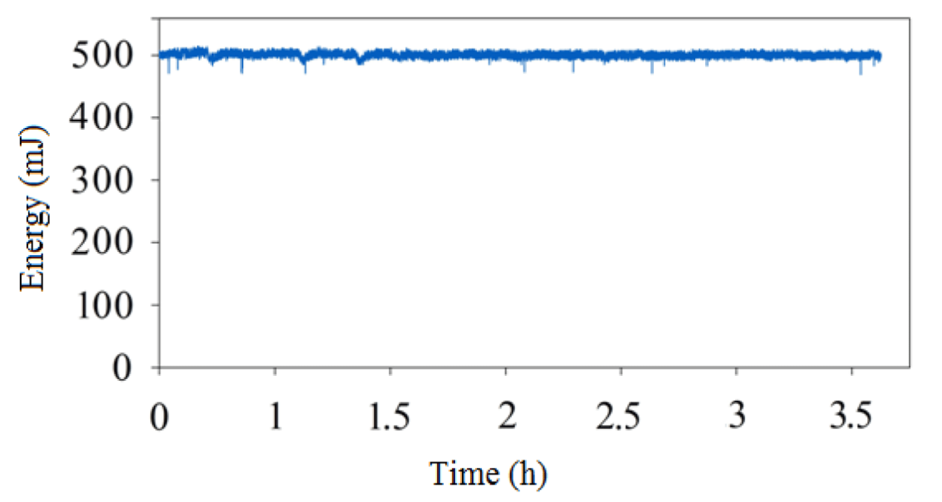
Figure 11. Output energy stability at 0.2 Hz.
After wavefront assessment, a pulse from the front end was injected into the main amplifier; the beam was propagated through the amplifier repeatedly until reaching the maximum output energy. Figure 10 shows the output energy from the amplifier as a function of the number of extraction passes with different repetition rates for a pump pulse duration of $500~\unicode[STIX]{x03BC}\text{s}$
, equivalent to a total pump energy of 7.3 J. An output pulse energy of 0.5 J, corresponding to a saturation fluence of
$500~\unicode[STIX]{x03BC}\text{s}$
, equivalent to a total pump energy of 7.3 J. An output pulse energy of 0.5 J, corresponding to a saturation fluence of $1~\text{J}/\text{cm}^{2}$
, was obtained with 20 passes for a seed input of
$1~\text{J}/\text{cm}^{2}$
, was obtained with 20 passes for a seed input of ${\sim}0.6~\text{mJ}$
at a repetition rate of 0.2 Hz, while the maximum output energy was 0.43 J at a repetition rate of 0.5 Hz for the same seed energy. These were compared with theoretical predictions from a numerical model. Measured results agree well with the theoretical predictions and, in both cases, gain saturation occurs within the amplifier at 20 passes. Figure 11 shows the output energy of the system for 3.5 h with 0.69% rms overall energy stability at 0.2 Hz. Based on the same theoretical parameters, a combined energy output of 1.2 J is predicted at about 11 passes for a gain of 2.6 (see blue line in Figure 10), meaning that increasing pump energy can achieve more than one joule of amplification under the same conditions. The burn pattern of the amplifier output at 0.5 J and 0.2 Hz was shown inset in Figure 10, which was measured using a laser alignment paper provided by a local manufacturer Leijie technology. There were some diffraction patterns in the beam similar to those in the gain distribution, which are the subject of ongoing investigation.
${\sim}0.6~\text{mJ}$
at a repetition rate of 0.2 Hz, while the maximum output energy was 0.43 J at a repetition rate of 0.5 Hz for the same seed energy. These were compared with theoretical predictions from a numerical model. Measured results agree well with the theoretical predictions and, in both cases, gain saturation occurs within the amplifier at 20 passes. Figure 11 shows the output energy of the system for 3.5 h with 0.69% rms overall energy stability at 0.2 Hz. Based on the same theoretical parameters, a combined energy output of 1.2 J is predicted at about 11 passes for a gain of 2.6 (see blue line in Figure 10), meaning that increasing pump energy can achieve more than one joule of amplification under the same conditions. The burn pattern of the amplifier output at 0.5 J and 0.2 Hz was shown inset in Figure 10, which was measured using a laser alignment paper provided by a local manufacturer Leijie technology. There were some diffraction patterns in the beam similar to those in the gain distribution, which are the subject of ongoing investigation.
4 Conclusion
We have reported on the results obtained from a LD-pumped gas-cooled multislab Nd:glass laser amplifier. At a repetition rate of 0.2 Hz, the amplifier generated 0.5 J of energy at 1053 nm for a pump energy of 7.3 J at 802 nm, while at 0.5 Hz an output energy of 0.43 J was obtained. Numerical models predicted that an energy output of 1.2 J could be obtained from the amplifier for a gain of 2.6. After shaping and homogenizing, the pump intensity distribution reached up to 85%. We also experimentally measured the single-pass thermally induced wavefront aberrations under the former conditions, which was approximately 96 nm P–V. This confirms the viability of the proposed multislab Nd:glass amplifier concept, which is scalable for larger apertures and higher energy levels. Further increases in output energies greater than 10 J are expected for design apertures of $20~\text{mm}\times 20~\text{mm}$
.
$20~\text{mm}\times 20~\text{mm}$
.
Acknowledgements
This project is supported by the Shanghai Science and Technology Foundation for Young Scholars (Grant No. 17YF1429600) and the National Natural Science Foundation of China (Grant No. 61705242).


 Open access