


1 Introduction
Raman fiber laser (RFL) can theoretically achieve emission at almost arbitrary wavelength with the help of proper pump wavelength[Reference Supradeepa, Feng and Nicholson1]; thus, the emission range of RFL is much broader than lasers based on rare earth-doped fibers. Therefore, RFL has been explored to achieve high-power output at specialized wavelengths[Reference Supradeepa and Nicholson2–Reference Zhang, Tao, Zhou, Wang and Xu10], which are rather challenging for lasing or amplifying efficiently by rare earth-doped fibers[Reference Zhou, Wang, Xiao, Ma and Chen11–Reference Xiao, Zhou, Wang, Guo and Xu13]. To date, high-power RFLs have been widely investigated and applied in optical pumping, frequency conversion, optical communications, biology and scientific research[Reference Fortin, Bernier, Faucher, Carrier and Vallée14–Reference Rakich, Fink and Soljacić22]. It is well known that the Raman gain in silica fibers extends over a large frequency range up to 40 THz[Reference Agrawal23]. In general, the frequency shift between pump wavelength and Raman wavelength is approximately 13.2 or 14.7 THz corresponding to the double-peak structure of Raman gain spectrum for silica fiber[Reference Agrawal23, Reference Vatnik, Zlobina, Kablukov and Babin24]. The frequency shift between the pump light and target Raman light is usually designed to be well matched to fulfill the peaks of Raman gain spectrum. For example, hundred-watt-level high-power RFLs operating at 1120 nm and 1150 nm were demonstrated by using 1070 nm and 1090 nm fiber lasers as pump sources, respectively[Reference Feng, Taylor and Calia3, Reference Zhang, Zhou, Wang, Du, Xiao and Xu17]. It is to be noted that, for application that requires RFLs with some specific wavelengths, it is usually not easy to obtain high-power pump source. The central wavelength of the pump source should match well with a 13.2 THz frequency shift compared with the output wavelength of RFL. For example, single mode 1178 nm RFL, which can be used for frequency doubling to the yellow, is often pumped by 1120 nm fiber laser. However, it is relatively difficult to achieve high-power lasing at 1120 nm based on Yb-doped fiber because of smaller net gain[Reference Zhang, Xiao, Zhou, Zhang, Wang and Xu25–Reference Wang, Hu, Zhang, Gu, Chen and Feng27] compared with shorter wavelength[Reference Jeong, Sahu, Payne and Nilsson28, Reference Jeong, Sahu, Payne and Nilsson29]. Therefore, it is interesting to explore the feasibility of generating high-power 1178 nm by pumping with a powerful Yb-doped fiber laser (YDFL) operating at ${\sim}1110~\text{nm}$
(or even shorter wavelength) corresponding to the frequency shift of
${\sim}1110~\text{nm}$
(or even shorter wavelength) corresponding to the frequency shift of ${\sim}15.6~\text{THz}$
, which has a significant difference compared with 13.2 THz. In fact, efficient lasing from a fiber Raman oscillator by fully exploring the broadband gain spectrum was studied as early as in 1977[Reference Jain, Lin, Stolen, Pleibel and Kaiser30, Reference Lin, French, Malone and Stolen31]. In the visible band, tunable Raman oscillator pumped by a 4 W argon ion laser at 514.5 nm was tuned over 8 nm using a prism, which corresponds to the frequency shift from 6.2 to 14.9 THz. In the infrared band, Stokes oscillation tuning from 1085 to 1130 nm corresponding to the frequency shift of 5.5 to 16.5 THz was obtained pumped by a 5 W Nd:YAG laser at 1064 nm. In 2008, Belanger et al. demonstrated a widely tunable RFL, the frequency shift of which ranged from 2.9 to 17.6 THz[Reference Belanger, Bernier, Faucher, Cote and Vallee32]. Almost constant output Stokes power, up to 5.0 W, was obtained when the frequency shift was from 10.5 to 14.0 THz. The output power of reported results is relatively low. However, high-power tunable RFL is required in some applications, such as nonlinear frequency conversion. In addition, the broad Raman gain spectral profile at high-power level needs to be further explored. When the frequency shift deviates significantly from the peak value, whether high-power and high-efficiency RFL could be achieved has not been studied in detail to date, to the best of our knowledge.
${\sim}15.6~\text{THz}$
, which has a significant difference compared with 13.2 THz. In fact, efficient lasing from a fiber Raman oscillator by fully exploring the broadband gain spectrum was studied as early as in 1977[Reference Jain, Lin, Stolen, Pleibel and Kaiser30, Reference Lin, French, Malone and Stolen31]. In the visible band, tunable Raman oscillator pumped by a 4 W argon ion laser at 514.5 nm was tuned over 8 nm using a prism, which corresponds to the frequency shift from 6.2 to 14.9 THz. In the infrared band, Stokes oscillation tuning from 1085 to 1130 nm corresponding to the frequency shift of 5.5 to 16.5 THz was obtained pumped by a 5 W Nd:YAG laser at 1064 nm. In 2008, Belanger et al. demonstrated a widely tunable RFL, the frequency shift of which ranged from 2.9 to 17.6 THz[Reference Belanger, Bernier, Faucher, Cote and Vallee32]. Almost constant output Stokes power, up to 5.0 W, was obtained when the frequency shift was from 10.5 to 14.0 THz. The output power of reported results is relatively low. However, high-power tunable RFL is required in some applications, such as nonlinear frequency conversion. In addition, the broad Raman gain spectral profile at high-power level needs to be further explored. When the frequency shift deviates significantly from the peak value, whether high-power and high-efficiency RFL could be achieved has not been studied in detail to date, to the best of our knowledge.

Figure 1. The experimental schematic of the linearly polarized Raman fiber laser. LP: linearly polarized; AMP: amplifier; GDF: germanium-doped fiber; CMS: cladding mode stripper.
In this paper, efficient high-power Raman lasing with extreme frequency shift between the pump and Stokes light was explored experimentally, based on an RFL cavity with fixed central wavelength. A homemade high-power wavelength-tunable master oscillator power amplifier (MOPA) with ${\sim}25~\text{nm}$
tunable working range was employed as pump source. All the fiber and fiber components involved are polarization maintained to eliminate the influence of polarization state. It is found that frequency shift located within 10.6 THz and 15.2 THz can ensure efficient Raman lasing, where the conversion efficiency is more than 95% of the maximal value of 71.3%. In addition, a maximum output power of 147 W was obtained with an optical efficiency of 71.3% at the pump wavelength of 1062.5 nm. The polarization extinction ratio (PER) of RFL is around 20 dB. This is the highest power ever reported in LP Raman fiber oscillators to the best of our knowledge. Before this, Surin et al. reported 65 W output power in linearly polarized (LP) RFL operating at 1178 nm, which is the highest-power in LP Raman fiber oscillators so far, as far as we know[Reference Surin, Borisenko and Larin21]. It is to be noted that the Raman Laser Module (RLM) and Raman Laser Rack (RLR) series produced by IRE Polus Group (IPG) Photonics Corporation can deliver up to 500 W RFL with optional LP operation[33]. However, the detailed configuration has not been revealed. In this case, the comparison is not taken into consideration.
${\sim}25~\text{nm}$
tunable working range was employed as pump source. All the fiber and fiber components involved are polarization maintained to eliminate the influence of polarization state. It is found that frequency shift located within 10.6 THz and 15.2 THz can ensure efficient Raman lasing, where the conversion efficiency is more than 95% of the maximal value of 71.3%. In addition, a maximum output power of 147 W was obtained with an optical efficiency of 71.3% at the pump wavelength of 1062.5 nm. The polarization extinction ratio (PER) of RFL is around 20 dB. This is the highest power ever reported in LP Raman fiber oscillators to the best of our knowledge. Before this, Surin et al. reported 65 W output power in linearly polarized (LP) RFL operating at 1178 nm, which is the highest-power in LP Raman fiber oscillators so far, as far as we know[Reference Surin, Borisenko and Larin21]. It is to be noted that the Raman Laser Module (RLM) and Raman Laser Rack (RLR) series produced by IRE Polus Group (IPG) Photonics Corporation can deliver up to 500 W RFL with optional LP operation[33]. However, the detailed configuration has not been revealed. In this case, the comparison is not taken into consideration.

Figure 2. (a) The spectrum and (b) the output power of the tunable pump source.

Figure 3. (a) The output power of the first-order Stokes wave versus pump wavelength; (b) the output spectrum as a function of pump wavelength.

Figure 4. The output power of first-order Stokes wave and corresponding conversion efficiency.
2 Experimental setup
The extreme frequency shift between the pump wavelength and Raman wavelength with high efficiency in high-power RFL was investigated in the experiment. As is shown in Figure 1, the experimental setup of the ${\sim}150~\text{W}$
level LP RFL was designed. The classical oscillator configuration was adopted because it has been well studied and it is beneficial to exclude the effect of other factors. A pair of fiber Bragg gratings (FBGs) centering at 1120 nm were adopted to fix the wavelength of the target Raman laser. The reflectivity of the high reflectivity (HR) FBG and the output coupler (OC) FBG is 99.6% and 50% at 1120 nm, with the full width at half maximum (FWHM) bandwidth of 1.5 nm and 0.45 nm, respectively. The FBGs were written on polarization maintaining (PM) fiber with
${\sim}150~\text{W}$
level LP RFL was designed. The classical oscillator configuration was adopted because it has been well studied and it is beneficial to exclude the effect of other factors. A pair of fiber Bragg gratings (FBGs) centering at 1120 nm were adopted to fix the wavelength of the target Raman laser. The reflectivity of the high reflectivity (HR) FBG and the output coupler (OC) FBG is 99.6% and 50% at 1120 nm, with the full width at half maximum (FWHM) bandwidth of 1.5 nm and 0.45 nm, respectively. The FBGs were written on polarization maintaining (PM) fiber with $10~\unicode[STIX]{x03BC}\text{m}/125~\unicode[STIX]{x03BC}\text{m}$
core/cladding diameter. A piece of commercial 31-m-long PM passive fiber (germanium-doped fiber, GDF) was selected to provide Raman gain, the core and inner cladding diameters of which are 10 and
$10~\unicode[STIX]{x03BC}\text{m}/125~\unicode[STIX]{x03BC}\text{m}$
core/cladding diameter. A piece of commercial 31-m-long PM passive fiber (germanium-doped fiber, GDF) was selected to provide Raman gain, the core and inner cladding diameters of which are 10 and $125~\unicode[STIX]{x03BC}\text{m}$
, respectively. The pump source is a homemade tunable 200-watt-level MOPA source with LP laser output, which is seeded by an LP YDFL and boosted by two stage amplifiers. LP configuration was designed because Raman gain is polarization-dependent, so in the experiment we can investigate the spectrum dependence of Raman gain regardless of the influence of polarization state. Cladding mode stripper (CMS) was achieved by coating high refractive index gel around the splicing point between the GDF and OC FBG to strip the cladding light and consequently protects the OC FBG. The output end was angle-cleaved to
$125~\unicode[STIX]{x03BC}\text{m}$
, respectively. The pump source is a homemade tunable 200-watt-level MOPA source with LP laser output, which is seeded by an LP YDFL and boosted by two stage amplifiers. LP configuration was designed because Raman gain is polarization-dependent, so in the experiment we can investigate the spectrum dependence of Raman gain regardless of the influence of polarization state. Cladding mode stripper (CMS) was achieved by coating high refractive index gel around the splicing point between the GDF and OC FBG to strip the cladding light and consequently protects the OC FBG. The output end was angle-cleaved to $8^{\circ }$
to suppress unexpected backward reflection.
$8^{\circ }$
to suppress unexpected backward reflection.
The tuning range of the pump source was from 1055 nm to 1080 nm. 1067.4 nm laser wavelength would be preferred because of the well-matched frequency shift (13.2 THz) compared with 1120 nm. Nevertheless, deviating from 1067.4 nm provides a flexible platform to investigate the gain property of RFL. The output properties of the tunable pump source were measured and recorded. As is shown in Figure 2(a), the pump source has 25 nm tuning range (from 1055 to 1080 nm), the FWHM linewidth of which, at different wavelengths, are all around 0.6 nm. Figure 2(b) depicts the maximum power of the pump source as a function of wavelength, which is all around 200 W. By recording and analyzing the output properties, the extreme frequency shift and the operating state of the Raman laser at different pump wavelengths were investigated.
3 Results and discussion
By comparing the output power and the corresponding conversion efficiency at different pump wavelengths, the extreme frequency shift between the pump wavelength and Raman wavelength in RFL was studied. The total output power (residual pump plus RFL output power) is around 155 W, corresponding to the slope efficiency of ${\sim}77.5\%$
. Figure 3(a) depicts the output power of the first-order Stokes wave at different pump wavelengths. As is shown in Figure 3(b), the frequency shift between the pump wavelength and the first-order Stokes wave and the frequency shift between the first- and second-order Stokes waves are almost the same. This phenomenon may be due to four wave mixing (FWM), which could be further investigated in the future.
${\sim}77.5\%$
. Figure 3(a) depicts the output power of the first-order Stokes wave at different pump wavelengths. As is shown in Figure 3(b), the frequency shift between the pump wavelength and the first-order Stokes wave and the frequency shift between the first- and second-order Stokes waves are almost the same. This phenomenon may be due to four wave mixing (FWM), which could be further investigated in the future.

Figure 5. (a) The output power as a function of pump power; (b) the spectrum at maximum power in the linear coordinate.
The difference among the first-order Stokes wave at different frequency shifts is further explored in Figure 4. As the frequency shift increases, the conversion efficiency of the first-order Stokes increases rapidly when the frequency shift is smaller than 10.6 THz, which corresponds to the wavelength longer than 1077.5 nm. At the frequency shift of 14.5 THz corresponding to the pump wavelength of 1062.5 nm, the maximum efficiency of 71.3% is obtained. From 10.6 to 15.2 THz corresponding to the wavelength from 1077.5 to 1060 nm, the efficiency changes a little around 70%. This efficiency is larger than 95% of the maximum value, 71.3%. It is to be noted that maximal conversion efficiency locates at the frequency shift of 14.5 THz instead of the theoretical value of 13.2 THz[Reference Agrawal23]. The phenomenon is due to the domination of the second peak in the double-peak structure in Raman gain profile, as was previously modeled based on power balance model considering different subcomponents with each Stokes component by Vatnik et al. in Ref. [Reference Vatnik, Zlobina, Kablukov and Babin24]. The maximum output power of 147.1 W is obtained at 1062.5 nm. When the frequency shift is larger than 15.2 THz, the efficiency begins to decline. Taking 16.5 THz and 15.2 THz as an example, although the frequency difference between them is only 1.3 THz, the difference of efficiency is up to 25.1%. The results indicate that the Stokes frequency downshifted from the pump frequency by 10.6 to 15.2 THz can operate with high power and high efficiency.

Figure 6. (a) The experimental setup of the comparative experiment; (b) the spectrum of comparative Raman fiber laser at 1062.5 and 1070 nm.
The whole system is specially designed to provide almost equal conditions for all the pump wavelengths. Sufficient conversion to the first-order Stokes wave and valid suppression of the second-order Stokes wave should be fulfilled at the same time. Taking the pump wavelength of 1070 nm as an example, the output properties of the Raman laser are recorded and analyzed. The power evolutions of the total output, residual pump, first-order Stokes wave and second-order Stokes wave are shown in Figure 5(a). The threshold power of Raman lasing is ${\sim}30~\text{W}$
. The maximum output power of 1120 nm Raman laser is 142.7 W under the pump power of 200.1 W, which corresponds to the optical efficiency of 71.3%. At the maximum pump power, the first-order Stokes wave occupies 95.0% of the whole spectrum, while the second-order Stokes wave at 1174.4 nm merely accounts for 0.2%, as is shown in Figure 5(b). Such a power difference between the first- and second- order Stokes wave is acceptable in our experiment.
${\sim}30~\text{W}$
. The maximum output power of 1120 nm Raman laser is 142.7 W under the pump power of 200.1 W, which corresponds to the optical efficiency of 71.3%. At the maximum pump power, the first-order Stokes wave occupies 95.0% of the whole spectrum, while the second-order Stokes wave at 1174.4 nm merely accounts for 0.2%, as is shown in Figure 5(b). Such a power difference between the first- and second- order Stokes wave is acceptable in our experiment.
Since the stimulated Raman scattering stems from the amplification of spontaneous Raman scattering, we also conducted a comparative experiment in order to further eliminate the effect of the FBGs. As shown in Figure 6(a), the output of the pump source is injected into the 1070 nm port of a 1070/1120 nm wavelength division multiplexer (WDM). A fiber loop mirror formed by splicing together the two output ports of a 50/50 coupler centering at 1120 nm and a flat-cut endface are adopted to form a cavity, where the feedback is nearly wavelength independent. A piece of 59 m GDF, which is longer than that in the Raman oscillator, is used to provide Raman gain in order to decrease the threshold power. The spectra of the output laser at the pump wavelengths of 1062.5 and 1070 nm are shown in Figure 6(b). The 1062.5 nm pump laser transforms to 1120 nm Stokes wave, while 1070 nm pump source converts to 1128 nm Stokes wave. The result shows that frequency shift of ${\sim}14.5~\text{THz}$
dominates in this laser system. This comparative experiment verifies that the highest conversion efficiency of the 1120 nm laser at the pump wavelength of 1062.5 nm is indeed owing to the highest Raman gain.
${\sim}14.5~\text{THz}$
dominates in this laser system. This comparative experiment verifies that the highest conversion efficiency of the 1120 nm laser at the pump wavelength of 1062.5 nm is indeed owing to the highest Raman gain.
The PER of the output laser is also measured based on the setup shown in Figure 7. The output laser goes through the collimator to guarantee collimation property. The residual pump and first-order Stokes wave are separated by the 1070/1120 nm dichroic mirror (DM). A half-wave plate working around 1120 nm is placed after it to adjust the polarization direction. The slow axis and the fast axis are split into two perpendicular directions by a polarization beam splitter (PBS) working around 1120 nm. The output powers of the two beams are recorded by the power meter 1 and power meter 2, respectively.

Figure 7. The measurement setup of PER.
The PER of the output laser can be calculated according to $\text{PER}=-10\log (a/b)$
, where
$\text{PER}=-10\log (a/b)$
, where $a$
and
$a$
and $b$
are the values of minor and major axes of the polarization ellipse, which correspond to the powers measured by the two power meters. The PER of the pump source can be obtained by measuring the PER of the residual pump when the pump power is less than the threshold power of
$b$
are the values of minor and major axes of the polarization ellipse, which correspond to the powers measured by the two power meters. The PER of the pump source can be obtained by measuring the PER of the residual pump when the pump power is less than the threshold power of ${\sim}30~\text{W}$
, as is shown in Figure 8. As the pump power increases, the PER evolution of the first-order Stokes wave is measured to be around 19.3 dB and there is no apparent degradation.
${\sim}30~\text{W}$
, as is shown in Figure 8. As the pump power increases, the PER evolution of the first-order Stokes wave is measured to be around 19.3 dB and there is no apparent degradation.

Figure 8. The PER of the residual pump and first-order Stokes wave at the pump wavelength of 1070 nm.
The power stability of the laser system was also measured and recorded, as is shown in Figure 9, the power stability of the output laser under the maximum pump power was monitored and recorded every 10 s at the time scale of 300 s by the power meter. The output properties at each pump wavelength were measured every less than 5 min. Therefore, in this case the entire recording time of laser stability is long enough. The standard deviation (STD) normalized to the mean value of the output power is calculated to be 0.0016, which indicates that the Raman laser is quite stable.

Figure 9. The stability of the output power at the time scale of 300 s.
As indicated in the introduction section, it is interesting to explore the feasibility of generating 1178 nm Raman laser with ${\sim}1110~\text{nm}$
pump source. The experimental results obtained before have indicated the probability, and now we will validate it through a proof-of-concept experiment. As shown in Figure 10, a 1178 nm random distributed feedback RFL [Reference Turitsyn, Babin, El-Taher, Harper, Churkin, Kablukov, Ania-Castañón, Karalekas and Podivilov34, Reference Du, Zhang, Xiao, Ma, Wang, Zhou and Liu35] was built based on a half open cavity[Reference Zhang, Jiang, Yang, Pan, Cui and Feng36, Reference Du, Zhang, Wang, Zhou and Liu37]. The pump source is a homemade fiber laser centered at 1111.6 nm, which corresponds to the frequency shift of 15.2 THz. An HR FBG and a piece of 1-km-long single mode fiber (SMF) are used to construct the setup of the half open laser cavity. The output endface is angle-cleaved to
${\sim}1110~\text{nm}$
pump source. The experimental results obtained before have indicated the probability, and now we will validate it through a proof-of-concept experiment. As shown in Figure 10, a 1178 nm random distributed feedback RFL [Reference Turitsyn, Babin, El-Taher, Harper, Churkin, Kablukov, Ania-Castañón, Karalekas and Podivilov34, Reference Du, Zhang, Xiao, Ma, Wang, Zhou and Liu35] was built based on a half open cavity[Reference Zhang, Jiang, Yang, Pan, Cui and Feng36, Reference Du, Zhang, Wang, Zhou and Liu37]. The pump source is a homemade fiber laser centered at 1111.6 nm, which corresponds to the frequency shift of 15.2 THz. An HR FBG and a piece of 1-km-long single mode fiber (SMF) are used to construct the setup of the half open laser cavity. The output endface is angle-cleaved to $8^{\circ }$
to suppress unexpected backward reflection so as to protect the pump source.
$8^{\circ }$
to suppress unexpected backward reflection so as to protect the pump source.

Figure 10. The experimental setup of 1178 nm Random laser.
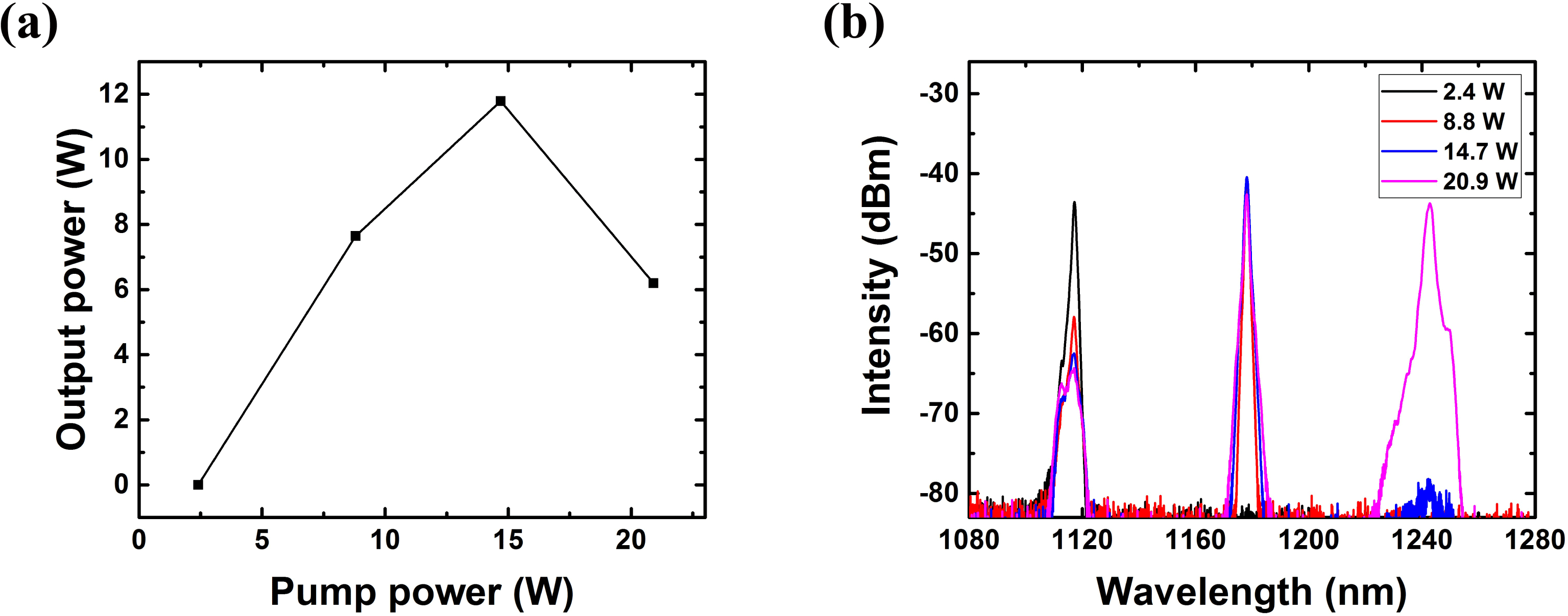
Figure 11. (a) The output power and (b) spectra versus pump power of 1178 nm random laser.
The output power and spectra as a function of pump power are shown in Figure 11. As the pump power increases, the output power increases at first and then decreases owing to the generation of second-order Stokes wave. The maximum output power is 11.8 W under the pump power of 14.7 W. The conversion efficiency of 80.2% is obtained at the maximum output power, which is sufficient to verify the potential of high power operation at 1178 nm pumped by high power 1111.6 nm fiber laser.
4 Conclusion
In summary, we report an experimental investigation on the extreme frequency shift between the pump wavelength and Raman wavelength in a high-power LP RFL. A pair of FBGs whose central wavelength is 1120 nm are adopted to achieve fixed target Raman wavelength. A ${\sim}200~\text{W}$
LP wavelength-tunable pump source with 25 nm tuning range is used to change the frequency shift. A piece of 31-m-long PM silica passive fiber is selected to provide Raman gain. By comparing the properties of power, efficiency and spectra as the pump wavelength tunes from 1055 to 1080 nm, the range of frequency shift that can demonstrate high-power and high-efficiency Raman lasing is achieved. The experimental results verify that Raman laser with the frequency downshifted from the pump frequency by 10.6 to 15.2 THz operates with high efficiency, which is higher than 95% of the maximum one of 71.3%. At the same time, the maximum output power of 142.7 W is obtained with an optical efficiency of 71.3%, which is the highest power ever reported in LP RFLs to the best of our knowledge. As a typical application example of the results obtained in this paper, we experimentally verify that the 1120 nm pump laser could be replaced with a
${\sim}200~\text{W}$
LP wavelength-tunable pump source with 25 nm tuning range is used to change the frequency shift. A piece of 31-m-long PM silica passive fiber is selected to provide Raman gain. By comparing the properties of power, efficiency and spectra as the pump wavelength tunes from 1055 to 1080 nm, the range of frequency shift that can demonstrate high-power and high-efficiency Raman lasing is achieved. The experimental results verify that Raman laser with the frequency downshifted from the pump frequency by 10.6 to 15.2 THz operates with high efficiency, which is higher than 95% of the maximum one of 71.3%. At the same time, the maximum output power of 142.7 W is obtained with an optical efficiency of 71.3%, which is the highest power ever reported in LP RFLs to the best of our knowledge. As a typical application example of the results obtained in this paper, we experimentally verify that the 1120 nm pump laser could be replaced with a ${\sim}1111~\text{nm}$
pump laser for a 1178 nm RFL, which is more beneficial to provide high-power pump lasers. The results could help expand the frequency shift in cascaded RFL or select appropriate frequency shift to generate Raman laser at special waveband, while the efficiency would not be reduced compared to the classic frequency shift. The FWM phenomenon observed in the experiment will be further investigated in the near future. The extreme frequency shift in other configurations, such as integrated ytterbium-Raman fiber amplifier and pure Raman amplifiers, could also be investigated in the future.
${\sim}1111~\text{nm}$
pump laser for a 1178 nm RFL, which is more beneficial to provide high-power pump lasers. The results could help expand the frequency shift in cascaded RFL or select appropriate frequency shift to generate Raman laser at special waveband, while the efficiency would not be reduced compared to the classic frequency shift. The FWM phenomenon observed in the experiment will be further investigated in the near future. The extreme frequency shift in other configurations, such as integrated ytterbium-Raman fiber amplifier and pure Raman amplifiers, could also be investigated in the future.
Acknowledgements
This work was supported in part by the Huo Yingdong Education Foundation of China (No. 151062), in part by the Foundation for the author of National Excellent Doctoral Dissertation of China (No. 201329), and in part by the National Natural Science Foundation of China (No. 61635005).


 Open access