


1. Introduction
Inertia fusion energy (IFE) is recognized as a clean energy. The solid-state laser is one of the most competitive technical approaches for fusion energy drivers. IFE puts forward new and higher technology requirements for solid-state laser drivers, which are different from the inertial confinement fusion (IFC) laser driver. IFE includes the following main characteristics: high power, high repeat frequency/high efficiency and high reliability. These characteristics constitute the key advantages of the new generation of solid-state laser drivers. The requirement of repetition frequency is the prominent difference between ICF and IFE laser drivers. The thermal effect is a key technical problem which must be solved[Reference Chanteloup, Albach, Arzakantsyan, Novo and Vincent1–Reference Zheng, Jiang, Yan, Zhang, Wang, Wu, Tian, Zhang, Li, Zhu, Su, Jing and Zheng5]. The current international development of research on fusion energy drivers demonstrates that each has its merits. The choices of materials and thermal management are also different. Yb:YAG and Nd:glass are two kinds of suitable materials. Yan has researched the energy storage characteristics of the two kinds of materials[Reference Yan, Zheng, Jiang, Wang, Zhang and Li6]. In this paper, the thermal characteristics of these two kinds of materials are analyzed, in respect of temperature, thermal deformation and thermal stress. The depolarization result from thermal stress was simulated. Because the depolarization will make frequency doubling efficiency decline, so it should be compensated. In classical literature, the method of depolarization compensation was always the placing of a polarization rotator between two identical amplifiers[Reference Frede, Wilhelm, Brendel, Fallnich, Seifert, Willke and Danzmann7, Reference Frede, Wilhelm, Gau, Brendel, Zawischa, Fallnich, Seifert and Willke8]. A rotator rotates the polarization by  $90^{\circ }$. For full compensation, the two amplifiers should accord and the laser should pass through them in a symmetrical position. However, for a practical laser, realistically non-uniform pumping will exist, and it will be difficult to make two amplifiers completely the same. In this paper, we consider another method to compensate the depolarization.
2. Theory and numerical analysis
The temperature distribution of laser disks was determined by heat production rate, heat transfer coefficient and thermal performance of the laser medium. The expressions are
 $$\begin{eqnarray}\left\{\begin{array}{@{}l@{}}{\it\rho}C\displaystyle \frac{\partial T(x,y,z)}{\partial t}=k\left(\frac{\partial ^{2}T}{\partial x^{2}}+\frac{\partial ^{2}T}{\partial y^{2}}+\frac{\partial ^{2}T}{\partial z^{2}}\right)+q_{v}\quad \\ T(x,y,z;0)=T_{0}\quad \\ \displaystyle \left.-{\it\kappa}\frac{\partial T}{\partial \vec{n}}\right|_{\sum i}=h_{c_{i}}(T-T_{\text{gas}}),\quad \end{array}\right.\end{eqnarray}$$
 where  $\sum$ is the surface of the laser slab, ${\it\kappa},{\it\rho},c$ are, respectively, thermal conductivity coefficient, mass density and heat capacity of the laser slab, $h_{c}$ is the coefficient of heat transfer and $q_{v}$ is the heat production rate.
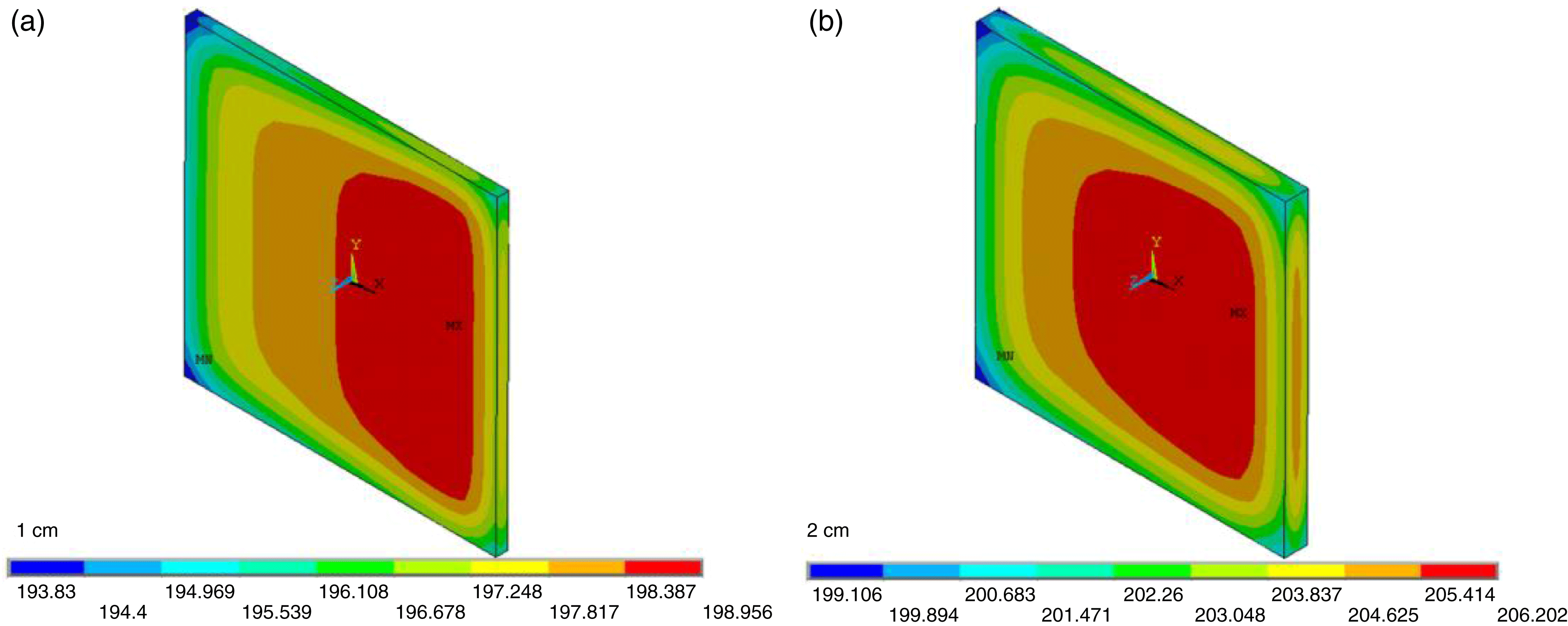
Figure 1. Temperature distribution of Yb:YAG: (a) temperature of 1 cm Yb:YAG; (b) temperature of 2 cm Yb:YAG.
With the increase of temperature, the laser disk should expand, but it will always be restricted, which will generate thermal stress. In addition the generated stresses induce birefringence, and then the laser will be depolarized and the wavefront will be aberrant.
Firstly, the temperature of the laser medium was calculated by a finite-element program; secondly, the thermal stress and displacement were calculated through a coupled program; thirdly, the raise of temperature, displacement, and thermal stress were exported to an optical program with a MATLAB code which can calculate the wavefront and depolarization.
To calculate the temperature, the pumping power and distribution should be given. Two kinds of pumping distribution were calculated, one is a uniform distribution, the other is a non-uniform distribution which was measured by CCD in a practical laser.
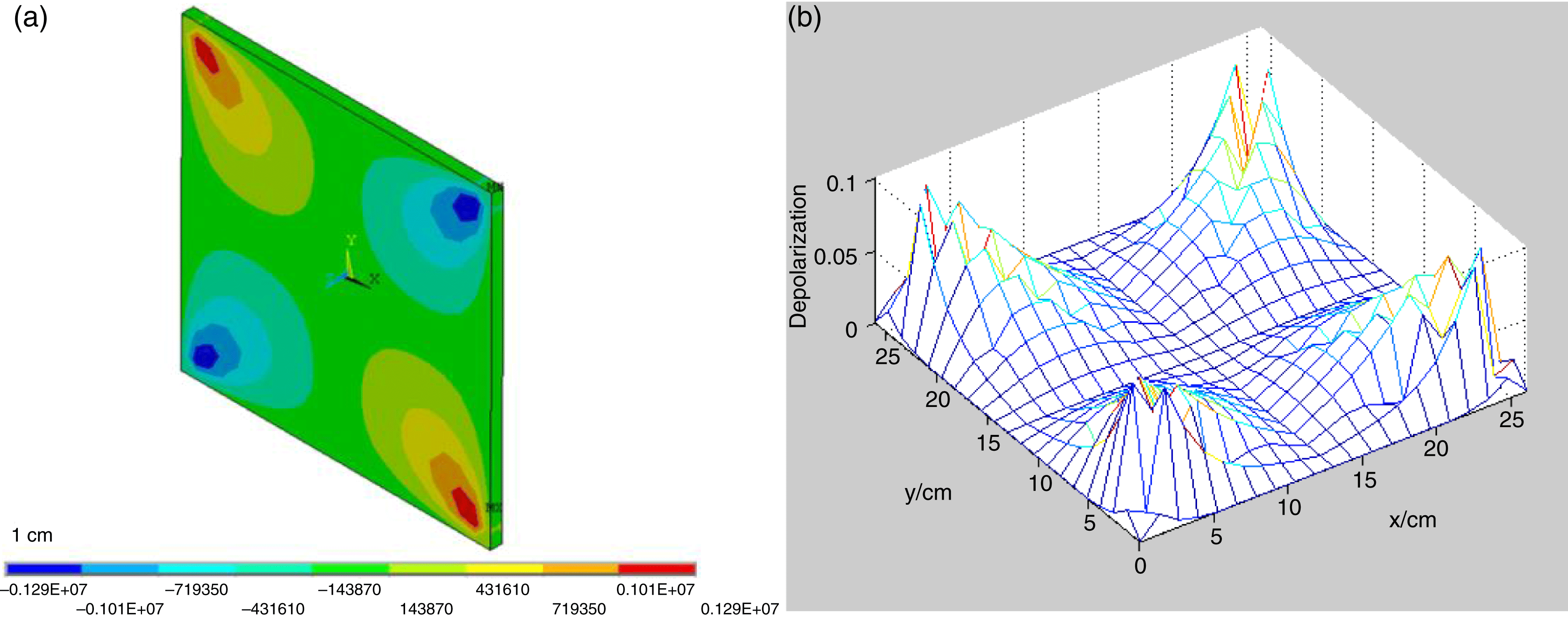
Figure 2. (a)  $xy$ shear stress of Yb:YAG; (b) depolarization of one disk.
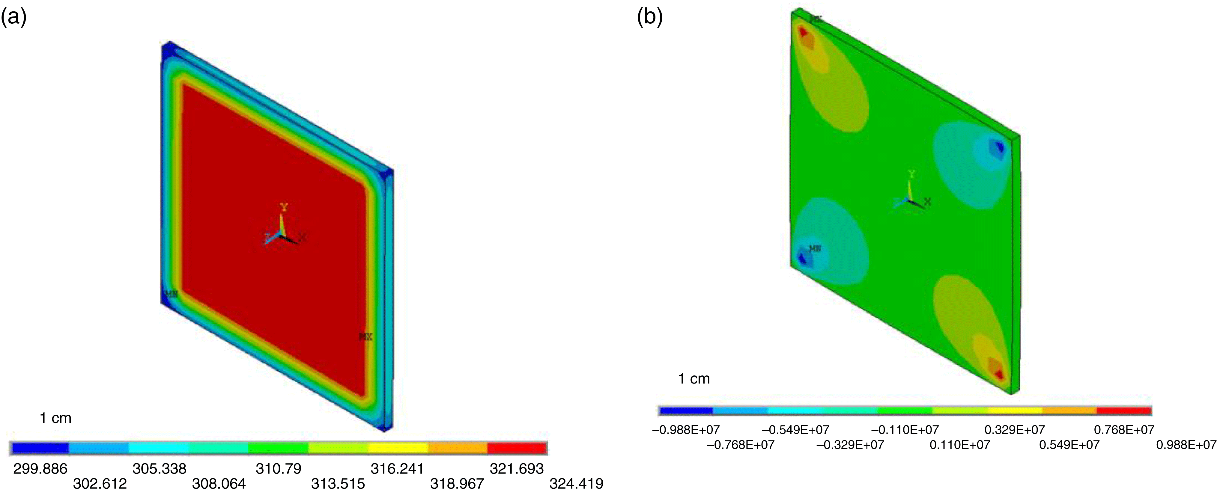
Figure 3. (a) Temperature distribution and (b)  $xy$ shear stress of Nd:glass.
3. Thermal analysis of Yb:YAG and Nd:glass with uniform pumping
The advantages of Yb:YAG are high thermal conductivity, high thermal shock resistance and low heat generation rate. The disadvantage of Yb:YAG, however, is the low absorption cross section and emission cross section at room temperature, which reduces the requirement of high pumping and high laser fluence. Yb:YAG has a high pumping saturation intensity ( $28\;\text{kW}\;\text{cm}^{-2}$). Therefore high pumping intensity is needed to improve optical efficiency and this results in high thermal power density, particularly in high-repetition-rate operation. The Boltzmann thermal population of the lower laser level is affected significantly by temperature. Cryogenically cooled Yb:YAG has significant potential for high-average-power solid-state lasers with good spatial beam quality because of the material’s excellent thermo-optic and spectroscopic properties at low temperatures. For example, YAG has a significantly higher thermal conductivity, lower thermo-optic coefficient $dn/dT$, and lower coefficient of thermal expansion than at room temperature. Each of these properties results in a reduction of thermo-optic effects at low temperature. For example, at 100 K Yb:YAG energy levels become four level, the saturation intensity decreases, the quantum defect is only 9%, and an absorption band at 940 nm remains broad enough for diode pumping. According to the energy fluence design[Reference Yan, Zheng, Jiang, Wang, Zhang and Li6], the optimized working temperature is from 190 to 200 K, the pumping power density on a single surface is $22.5\;\text{kW}\;\text{cm}^{-2}$, the pumping pulse duration is $300\;{\rm\mu}\text{s}$, the beam aperture is $26\;\text{cm}\times 26\;\text{cm}$, and the total thickness is 20 cm. As a result of the total thickness being too large, it is necessary to cut the medium into several pieces to improve cooling capability.
Different thicknesses of Yb:YAG were calculated which included 1 and 2 cm. The temperature distribution of Yb:YAG is shown in Figure 1. Because the temperature of 2 cm Yb:YAG was too high, we adopted a 1 cm medium as the design point. The thermal stress and depolarization of 1 cm Yb:YAG were calculated and the results are shown in Figure 2.
For 1 cm thickness Yb:YAG, the maximum temperature rise was 9 K, the maximum  $xy$ shear stress was $1.29\times 10^{6}~\text{Pa}$, and the maximum depolarization of electric field through one disk was less than 0.1.
The advantages of Nd:glass include the ease of obtaining large sizes and the fact that the temperature to translation effect can be ignored. The disadvantages of Nd:glass include low thermal conductivity and low quantum efficiency. The thermal effect of Nd:glass was calculated, with a thermal power density of  $2.27\;\text{W}\;\text{cm}^{-3}$ and a surface heat transfer coefficient of $500\;\text{W}\;\text{m}^{-2}\;\text{K}^{-1}$, for a thickness of Nd:glass of 1 cm. The temperature and shear stress are shown in Figure 3. The depolarization is shown in Figure 4.
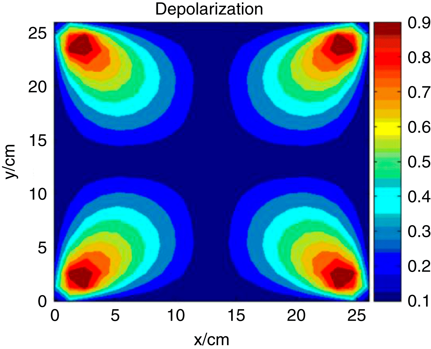
Figure 4. Depolarization of one Md:glass disk.
For a 1 cm Nd:glass disk, the maximum temperature rise was 59 K and the maximum  $xy$ shear stress was $9.88\times 10^{6}~\text{Pa}$; the maximum depolarization of electric field through one disk was 0.9.
From the calculated results, the thermal effect of Yb:YAG was less than Nd:glass. This is because Yb:YAG has higher thermal conductivity. In addition, in the high-average-power mode, the temperature gradient and the depolarization inside the medium cannot be avoided. The depolarization loss makes Brewster’s angle slab amplifiers unsuitable for IFE lasers, because they can cause near field beam modulation and energy loss.

Figure 5. Non-uniform pumping distribution measured by CCD.
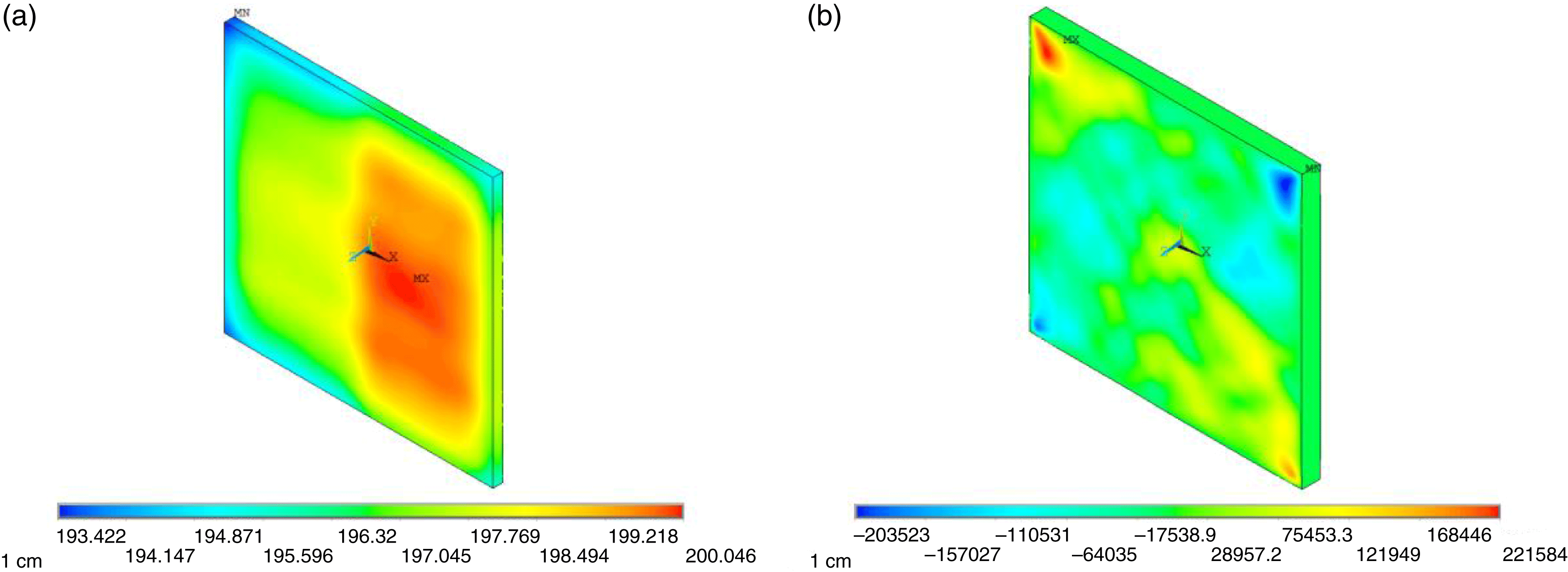
Figure 6. (a) Temperature distribution and (b)  $xy$ shear stress of Yb:YAG with non-uniform pumping.
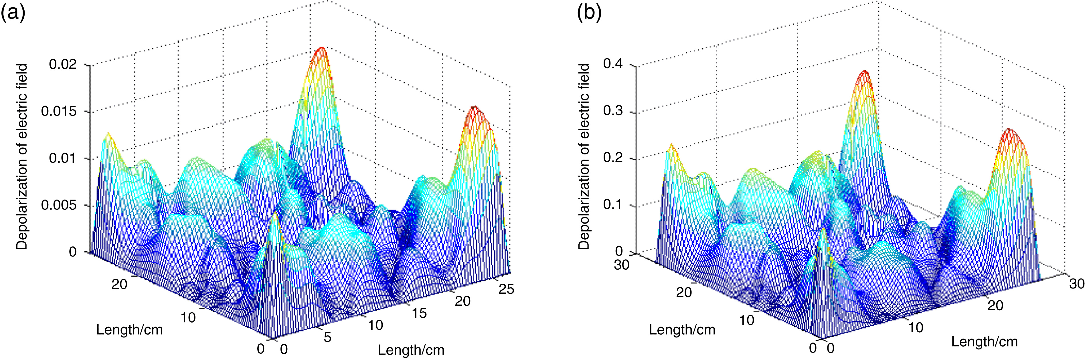
Figure 7. The depolarization of the laser passing through (a) one disk and (b) twenty disks.
4. Thermal analysis of Yb:YAG with non-uniform pumping
In a practical laser, because it is difficult to make the pumping distribution very uniform, the pumping distribution will always be modulated. The non-uniform pumping will make the temperature of the laser medium more asymmetric and then the stress and depolarization will be different from a medium pumped uniformly.
An experimental pumping distribution was used to calculate the thermal effect of Yb:YAG. The pumping distribution is shown in Figure 5. The temperature and  $xy$ shear stress are shown in Figure 6. As you can see, the distribution of temperature and $xy$ shear stress were not uniform and were asymmetric. The depolarization of the laser passing through the Yb:YAG was calculated. The depolarization of the laser passing through one disk and through twenty disks is shown in Figure 7. As you can see, the depolarization in Figure 7 is not inerratic or symmetrical. The undulation of depolarization in space is more acute than it is in Figure 2 which was pumped with a uniform distribution. We can deduce that if the medium was pumped with another non-uniform pumping distribution, the distribution of depolarization would be different from Figure 7.
5. Depolarization compensation
In classical literature, the method of depolarization compensation was always the placing a polarization rotator between two identical amplifiers. A rotator rotates the polarization by  $90^{\circ }$. For full compensation, the two amplifiers should accord and the laser should pass through them in a symmetrical position. However, for a practical laser, realistically non-uniform pumping will exist, and it will be difficult to make the two amplifiers completely the same.
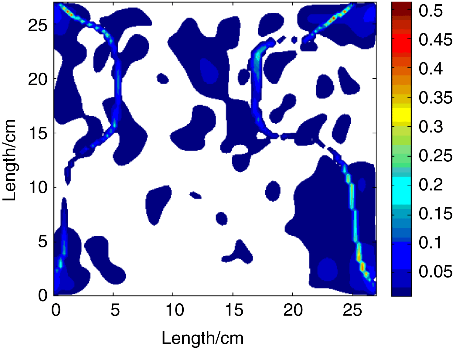
Figure 8. The residual depolarization caused by light excursion.
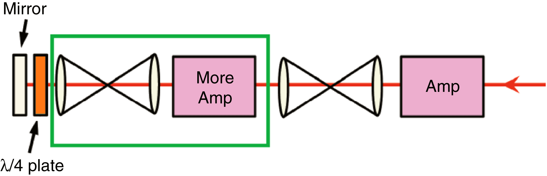
Figure 9. Schematic of depolarization compensation.
In this condition, we consider compensating the depolarization of one amplifier by itself. Using a Quartz rotator after the amplifier and putting a high reflection mirror after the rotator, the laser will pass through the amplifier twice with the polarization rotated  $90^{\circ }$. For a parallel beam, the depolarization will be compensated completely. But if the beam has a large aberrance, the effect of compensation will be reduced. The deterioration of compensation was affected by the gradient of the depolarization in space and the aberration of the beam. An elementary simulation of the deterioration of compensation caused by light excursion was performed. Figure 8 shows the residual depolarization caused by light excursion which was 0.014 rad (this is a large value determined by the gridding of my calculation). As you can see, the deterioration of compensation is not uniform in space, and is severe in the area of the large depolarization gradient.
A good wavefront and image relay will be necessary. Figure 9 shows the compensation schematic. In this way, we can use more amplifiers with different parameters.
6. Conclusion
The thermal effects of two kinds of laser material were simulated. The temperature gradient and the depolarization inside the medium cannot be avoided. The depolarization loss makes Brewster’s angle slab amplifiers unsuitable for IFE lasers, because they can cause near field beam modulation and energy loss. In a practical laser, the pumping distribution is not very uniform and one cannot make all amplifiers identical to each other, so we consider a compensation method which compensates the depolarization by itself.
Acknowledgement
This work was supported by the Fusion Energy Center of CAEP (R-2014-0202-02).


 Open access