


Introduction
Ice cores provide seasonal- to millennial-resolution records of climate that in some cases extend back multiple glacial cycles. Isotope and chemical variations in the deposited snow and gases within trapped bubbles provide proxy records for many aspects of the paleoenvironment, including temperature, ice accumulation rate, moisture source, atmospheric dust loading (and dust source), green house-gas concentration, and bioproductivity. Also, as with modern climate, our understanding of paleoclimate spatial variability is limited by the spatial resolution with which it is sampled. Each new core affords new insight for identifying patterns of circulation and for separating local weather signatures from global-scale climate processes.
The essential objective for deep ice cores is to obtain a faithful climate record. Several factors contribute to a site’s suitability for coring. Fundamentally, its geographic location should be influenced by weather-system patterns that are unambiguously interpretable in the record as well as robust indicators of global-scale climate processes. the site needs to be considered in the context of both theoretical studies of the climate system and previous ice-coring results. Also, environmental conditions at the site should be conducive to preservation of climatic records. the accumulation rate and its seasonality, the surface temperature, and windiness are among the factors that characterize the depositional environment. These characteristics need to be established with ground-based sampling.
In anticipation of future deep coring activities near the Ross/Amundsen ice-flow divide (Fig. 1), an objective of the U.S.–International Trans-Antarctic Scientific Expedition (US–ITASE) program is to carry out just such a surface glaciochemistry sampling over a large region of West Antarctica. Once completed, the results will greatly enhance those of a 1995/96 exploratory traverse (Reference Kreutz, Mayewski, Twickler and WhitlowKreutz and others, 1996) in which three firn cores were collected and climatic signal preservation in this vicinity was established (e.g. Reference Kreutz, Mayewski, Meeker, Twickler and WhitlowKreutz and others, 2000).We strive to guide further ground-based activity, and ultimately deep coring, by considering glaciological factors that influence the preservation of a deposited record, i.e. the time-scale and temporal resolution of any recovered record and potential for disruption of the oldest portions of that record. Our analyses extend those of Reference Nereson, Waddington, Raymondand and JacobsonNereson and others (1996) by relying on new, detailed ice-sheet morphology measurements.
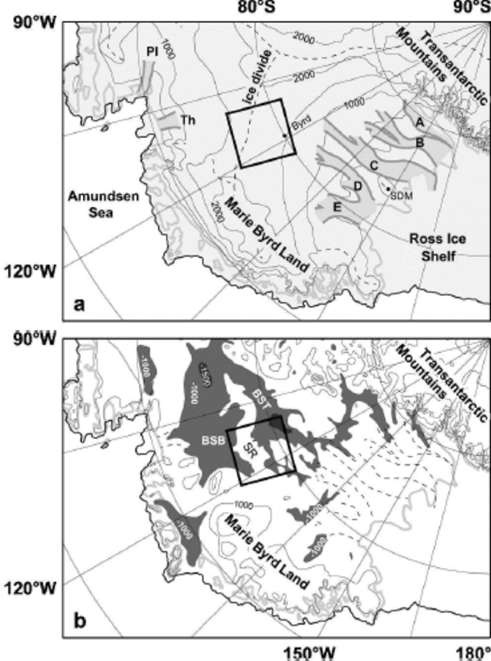
Fig. 1 Surface (a) and bed (b) elevation maps of West Antarctica (Reference DrewryDrewry, 1983) showing location of Ross Sea/Amundsen Sea ice-flow divide that separates flow southwestward to the Ross Sea via the Siple Coast ice streams (A–E) and northward to the Amundsen Sea via Pine Island (PI) and Thwaites (Th) Glaciers. Bed elevations below –1000 m are shaded to show that much of the bed beneath the West Antarctic ice sheet lies well below sea level, deepening toward its interior, and that the Ross Sea and Amundsen Sea drainages have direct access to this region. the two primary basins in the region, the Byrd Subglacial Basin (BSB) and Bentley Subglacial Trench (BST) are separated by the Sinuous Ridge (SR). the central, inscribed box is the boundary of Figures 2 and 4–7.
The depth–age profile is determined primarily by accumulation rate and ice thickness. for a given ice thickness, a site with lower accumulation rate will obviously have a less detailed recent record; however, it may have a more detailed older record in ice that has undergone less vertical strain than its contemporary ice at a higher-accumulation-rate site. Choosing a site with thicker ice will tend to improve temporal resolution throughout the ice column, compared with a site with thinner ice. But a limit can be reached for thick-ice, low-accumulation-rate sites: geothermal heating may be sufficient that basal melting occurs and the oldest part of the record is lost. Indeed, the potential for basal melting is an especially important consideration for any deep coring site in West Antarctica. Since much of the West Antarctic ice-sheet (WAIS) bed lies approximately 1 kmbelow sea level, the surface is comparatively lower and thus warmer when compared with ice-core sites in Greenland or East Antarctica where the ice thickness is comparable. Perhaps more significantly, the WAIS rests on thinned and extended crust that has elevated geothermal flux compared with Precambrian cratons (Reference Blankenship, Alley and BindschadlerBlankenship and others, 2001; Reference Dalziel, Lawver, Alley and BindschadlerDalziel and Lawver, 2001). Anecdotally, water was observed at the base of the Byrd ice core (Fig. 1), suggesting that it may have been melting.
Factors in addition to time-scale and thermal regime should also be considered. A special ice-flow pattern develops at a divide, where weak, longitudinal tension dominates the state of stress, and the ice deforms in pure shear. If layers in the ice have differing rheological properties, this flow configuration can cause boudinage and consequent stratigraphic disturbance (e.g. Reference Staffelbach, Stauffer and OeschgerStaffelbach and others, 1988; Cunningham and Waddington, 1990). on each flank of the divide, the stress state is dominated by bed-parallel simple shear. With increasing distance from the divide, the shear strain rate increases and, along with it, the potential for flow instabilities that could buckle and even fold layers of the stratigraphic column (e.g.Reference Waddington, Bolzan and AlleyWaddington and others, 2001). Evidence for flow disturbances such as these is difficult to obtain from the surface, but we need to be aware that they can exist. Sites more than approximately 10 ice thicknesses from the flow divide should be avoided. Divide sites may offer the potential for longer, less disturbed records, though this may be offset by the risk of thermal anomalies and boudinage. With radar sounding profiles we can observe (and hence avoid) large-scale flow disturbances associated with flow over steeply undulating bedrock topography. Any site that we consider should display smooth, flat-lying internal stratigraphy, and it should have smooth bed topography upstream of its location.
First we present new aerogeophysical survey results that give a detailed view of ice-sheet morphology and an indication of sub-ice geology in the Ross/Amundsen flow-divide region. Then we identify seven candidate deep coring sites and evaluate their thermal regime and potential for basal melting. Finally we estimate depth–age scales for the potential sites and discuss their relative merits for paleoclimate recovery in terms of temporal resolution and record duration.
Morphology of the Ross/Amundsen Ice-Flow Divide
A campaign of aerogeophysical surveys was conducted in central West Antarctica during 1994–96 (Reference Blankenship and BellBlankenship and others, 1994; Reference Richter, Williams, Blankenship and BellRichter and others, 1996). We report on a subset of these surveys that covered the central portion of the Ross/ Amundsen ice-flow divide (Fig. 1). the survey consists of a 222.6 km square grid that was flown at 5.3 km line spacing. Instrumentation and data analysis used for these surveys were similar to those described by Reference Blankenship, Alley and BindschadlerBlankenship and others (2001): the aerogeophysical instrumentation package included an ice-penetrating radar, laser ranger, gravimeter and magnetometer. Aircraft positions were determined by kinematic post-processing of differential carrier-phase global positioning system (GPS), and a laser-gyro inertial navigation system provided aircraft attitude measurements. We augment these data with results from a 1999/2000 survey that consists of a series of 12 paths ~120 km long, each crossing the divide along the direction of maximum surface slope (and presumably ice flow).
Surface topography
For each survey line, measurements of laser range, aircraft attitude and position were synchronized and combined to give profiles of ice surface elevation. Comparison of measurements at line intersections gives an rms discrepancy of approximately 0.20m (Reference Blankenship, Kempf, Morse, Peters, Bell, Arko and CsathόBlankenship and others, 1999). Within the survey region, the flow divide is a northwest–southeast-trending ridge that includes a bedrock-controlled dome near 114˚W, 79˚ S, and saddles to its northwest and southeast (Fig. 2). the surface falls off gradually to the southwest, with a mean slope of approximately 2610–3, supplying ice to the Ross Sea. Subtle surface undulations are evident, a consequence of ice flowing over basal relief (e.g. Johannesson, 1992). Coverage on the Amundsen Sea side of the ice divide is limited, extending only 120 km at most. Close to the divide, the surface slopes are steeper on the north (Amundsen) side, where they average 3610–3. Surface undulations are also more pronounced on the Amundsen Sea side, resulting from greater topographic relief of the bed and shallower ice.

Fig. 2 Ice-surface elevation from airborne laser altimetry. the line-based observations have been gridded at 425 m resolution using a bicubic spline that is spatially filtered to reject features smaller than the 5.3 km line spacing. the contour interval is 25 m. Flight tracks are shown by thin dotted lines. the locations of candidate coring sites A–G, the Byrd core site and the Noel automatic weather station location are marked here and in Figures 4–7 .The inscribed box marks the boundary of the 222.6 km square survey region; data shown outside this region are not constrained by gridded sampling.
Ice thickness and accumulation rate
Ice-thickness measurements are the principal application for ice-penetrating radar (Fig. 3). We extracted the arrival times of the surface and bed echoes from the radar waveforms using an automatic signal-detection algorithm, with manually set search bounds (see Reference Blankenship, Alley and BindschadlerBlankenship and others, 2001). We use a wave speed of 168.4 mμs–1 to calculate effective ice thickness using this two-way travel time; no firn correction was applied. Crossover analysis gives an rms discrepancy of 56 m for the entirety of the 1994–96 thickness measurements. Ice thickness along the Ross/Amundsen flow divide ranges between approximately 2000 and 3500m (Fig. 4). Ice as thin as approximately 1200m can be found 80 km to the north of the divide, and ice as thin as 330 m, over ``Mount Resnik’’ (Fig. 6) 240 km south of the divide. the bed echo could not be detected in much of the southeast corner of the survey, likely due to dielectric absorption of radio-wave energy in the thick ( >3800m), warm ice overlying the Bentley Subglacial Trench (BST; see Fig. 1).

Fig. 3 Example of an “intensity-modulated” radar profile that crosses the flow divide at the location of site A (red vertical line). the echo waveforms have been shifted to align the surface returns to the image top. At site A the bedrock echo appears at approximately 2900 m depth. Depth variations of ice electrical properties, associated primarily with depositional processes, create the pattern of internal reflecting horizons (``layers’’) that dominate the upper ~80% of the ice thickness. the blue line marks the layer that was used to derive the spatial pattern of accumulation shown in Figure 5.

Fig. 4 Ice-thickness measurements from airborne radar sounding. Track-line observations (tracks in Fig. 2) were gridded similarly to the surface elevations. In this figure, and in Figures 5–7, we include 25 m surface elevation contours for additional context.
Radar stratigraphy can be used to extrapolate ground-based accumulation-rate measurements over large areas since layers shallower than approximately 1000m reliably represent constant age horizons (isochrones), and layer depths are relatively undisturbed by spatially non-uniform accumulated strain (Reference MorseMorse and others, 1999) in approximately the upper third of the ice column. We have mapped a prominent, spatially continuous radar horizon (Fig.3) throughout the survey region by matching its depth at each profile intersection. We determine the regional accumulation-rate pattern (Fig. 5) from the depth of this layer by applying a Nye correction (Reference NyeNye, 1963) for accumulated vertical strain and calibrating, in a least-squares sense, to the firn-core accumulation measurements of Reference Kreutz, Mayewski, Meeker, Twickler and WhitlowKreutz and others (2000). the regional pattern, a strong accumulation-rate gradient with values increasing northward across the divide, results from a combination of orography and distance from the dominant Amundsen Sea moisture source (Reference HoganHogan,1997). Local variability is associated with subtle variations of surface slope and aspect, suggesting the interaction of deposition processes, such as scouring and drifting, with the surface undulations caused by basal relief (Reference MorseMorse and others, 1999).

Fig. 5 Accumulation rate determined by the burial depth of a spatially continuous radar horizon and calibrated by ground-based measurements at sites marked by squares. This is the mean accumulation rate over the past 2.5 kyr, as determined by the age of this layer in the Byrd ice core.
Bedrock topography
Discussion of the various candidate deep coring sites is facilitated by their placement in the context of bedrock topography, which is simply calculated from co-registered observations of surface topography and ice thickness. Distinct geologic units are evident in the bed topography (Fig. 6). Volcanic terrain of the ``Sinuous Ridge’’ (SR) (Reference Jankowski, Drewry, Behrendt, Oliver, James and JagoJankowski and others, 1983) dominates the northeastern portion of the survey. Bedrock elevations range between sea level and –1000m. Reference Behrendt, Finn, Blankenship and BellBehrendt and others (1998) hypothesized that plume-related mid- to late Cenozoic uplift of this feature was linked to the formation of a large volcanic caldera complex that they identified by its geomagnetic anomaly pattern (Fig. 7). Similarly, Reference Behrendt, Blankenship, Morse, Bell, Gamble, Skinner, Henrys and LynchBehrendt and others (in press) have hypothesized that the co-evolution of this caldera and the WAIS has resulted in a complex sequence of submarine, subglacial and subareal emplacement of volcanic constructs. Specifically, they propose that subglacially emplaced hyaloclastites have been removed, obscuring any simple relationship of magnetics and topography. If these hypotheses prove correct, the thermal anomaly associated with the plume emplacement will need to be considered further.

Fig. 6 Bed elevation showing dissected volcanic subglacial highlands of the ``Sinuous Ridge’’ to the north, smooth topography of the Bentley Subglacial Trench to the east and intermediate-elevation rolling topography to thewest. Note ``Mount Resnik’’ which rises from the depths of the BST to nearly penetrate the ice surface.

Fig. 7. Magnetic field intensity (Reference Sweeney, Finn, Blankenship, Bell and BehrendtSweeney and others, 1999) with 125 nT contours. the near-circular pattern of highs located under the ice divide is hypothesized by Reference Behrendt, Finn, Blankenship and BellBehrendt and others (1998) to be a large volcanic caldera, possibly mid-to late Cenozoic in age.
These data also reveal an approximately 15 km wide breach in the SR near 112˚W, 79˚ S that connects the BST south of the ice divide with the Byrd Subglacial Basin (BSB) north of the divide. These two deep basins, >1500m below sea level (Fig. 1b), are defining characteristics of the WAIS; their presence is thought to make the ice sheet susceptible to a retreat instability (Reference WeertmanWeertman, 1974; Reference HughesHughes, 1975). In the deepest sampled portions of the BST, where the radar could not detect the bed, sparse seismic measurements indicate it is near 2500m below sea level (Reference Bentley, Crary, Ostenso and ThielBentley and others, 1960). This region is thought to consist of depressed, thinned continental crust, associated with Cretaceous rifting.
Rolling terrain characterizes much of the survey’s eastern portion, with intermediate elevations ranging between –500 and –1500m. This region includes a system of bedrock channels that lie mostly parallel to the SR, perpendicular to regional ice flow. South and west of our survey region, such troughs tend to be occupied by a series of interconnected ``tributaries’’ (Reference JoughinJoughin and others, 1999) that feed the Siple Coast ice streams. from a balance-flux calculation, Reference Bamber, Vaughan and JoughinBamber and others (2000) suggest that one such filamentary flow feature that feeds Ice Stream D may enter the southwest corner of our survey, and extend nearly to the flow divide.
Candidate Sites for Deep Ice Coring
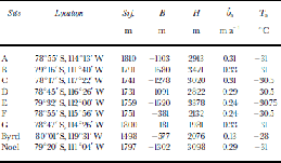
We identify seven deep-coring candidate sites that each display flat-lying radar stratigraphy and smooth bed both locally and upstream. These were chosen to sample the combinations of thin, intermediate and thick ice, as well as flank-and divide-flow regimes. Constraining the selection to sites within 10 ice thicknesses of the divide precludes much variation in accumulation rate (Fig. 5). We present geographic coordinates and essential glaciologic parameters for each of these sites in Table1. Sites A–Care at three characteristic sites along the ice divide: A is at the summit of the central dome that lies along the surface ridge; B and C are in the topographic saddles southwest and northeast of this dome. These sites also sample each of the three major bedrock terrains: A, coincidentally, falls at the center of the hypothesized caldera; B has very thick ice and accesses the breach connecting the BSB and the BST; and C is over a valley in the western, intermediate terrain. the flank-flow site D was earlier identified, principally for its flat-lying radar layering and smooth bed, as a target for a firn-coring traverse (Reference Kreutz, Mayewski, Twickler and WhitlowKreutz and others, 1996). Site E also has thick ice, giving a site similar to B, except for its location in a flank-flow regime. Site G offers the thinnest ice available anywhere in the region (within a suitable distance of the flow divide), accessing the highest portion of the subglacial highlands located under the divide. Site F is a flank-flowsite with similar ice thickness to G.
Table 1. Candidate site location, surface and bed elevation, ice thickness, accumulation rate and surface temperature interpreted from aerogeophysical survey results. for reference we include corresponding values of the Byrd core site and the Noel weather-station site
Thermo-Kinematic Modeling
We use a combination of a kinematic ice flow and an advection–diffusion heat transfer model to describe the thermal state of the ice sheet and to estimate the local depth–age scale and layer thickness at the selected sites. In addition to the ice thickness and accumulation rate, a description of the vertical velocity profile is needed for both temperature and depth– age calculations. Since the history of these parameters is poorly known, and local measurements of ice rheology, flow and temperature are not available, detailed dynamical thermomechanical calculations are unwarranted. We adopt a kinematic description of vertical ice motion that was originally described by Reference Dansgaard and JohnsenDansgaard and Johnsen (1969); we assume that the vertical thinning rate is constant down to a height h above the bed. Below h, the thinning rate decreases linearly to zero at the bed. Allowing for melting at the bed, these assumptions lead to a vertical velocity field given by:

in which z is the height above the bed, H is the ice thickness, ![]() is the accumulation rate at the surface and
is the accumulation rate at the surface and ![]() is the melting rate at the bed. the height h is usually a small fraction (e.g. 0.2) of the overall ice thickness; larger h values (e.g. 0.7) tend to better approximate the flow at ice divides. the Dansgaard–Johnsen formulation is often a good approximation to the velocity field predicted by fully mechanical flow calculations (Reference PatersonPaterson, 1994). In our formulation, the vertical velocity w(z) is linear in accumulation rate. for time-varying accumulation rate, we assume that the shape of the velocity profile is maintained, but its magnitude scales with the accumulation rate
is the melting rate at the bed. the height h is usually a small fraction (e.g. 0.2) of the overall ice thickness; larger h values (e.g. 0.7) tend to better approximate the flow at ice divides. the Dansgaard–Johnsen formulation is often a good approximation to the velocity field predicted by fully mechanical flow calculations (Reference PatersonPaterson, 1994). In our formulation, the vertical velocity w(z) is linear in accumulation rate. for time-varying accumulation rate, we assume that the shape of the velocity profile is maintained, but its magnitude scales with the accumulation rate ![]() A similar kinematic approach was applied for depth–age calculations for the Greenland Ice Sheet Project 2 (GISP2) ice core (Reference Cutler, Raymond, Waddington, Meese and AlleyCutler and others, 1995) and for interpreting time-varying flow geometry at Siple Dome (Reference Nereson, Raymond, Waddington and JacobelNereson and others, 1998). Reference Dahl-JensenDahl-Jensen and others (1997) used a similar approach to assess sites in North Greenland for the North Greenland Icecore Project (NorthGRIP) ice core.
A similar kinematic approach was applied for depth–age calculations for the Greenland Ice Sheet Project 2 (GISP2) ice core (Reference Cutler, Raymond, Waddington, Meese and AlleyCutler and others, 1995) and for interpreting time-varying flow geometry at Siple Dome (Reference Nereson, Raymond, Waddington and JacobelNereson and others, 1998). Reference Dahl-JensenDahl-Jensen and others (1997) used a similar approach to assess sites in North Greenland for the North Greenland Icecore Project (NorthGRIP) ice core.
Ice-column temperatures
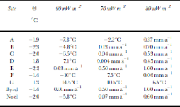
Ice-column temperature is governed by advection of cold ice from the surface and conduction geothermal flux from below. We model ice temperatures using a control volume formulation (Reference PatankarPatankar 1980) with 200 ice-control volumes and an additional 15 control volumes for bedrock. We use temperature-dependent ice thermal properties (Reference PatersonPaterson, 1994, p. 205) and the pressure-dependent melting temperature (Reference HobbsHobbs,1974, p.327). Local values of mean annual surface temperature (Table 1) were estimated from the surface elevation using a 10˚C km–1 lapse rate, tied to Byrd Station. for the surface boundary condition, we assumed a temperature and accumulation-rate history that mimics our expectation of the climate of the past glacial cycle (Fig. 8). We neglected the effects of thickness variations since their small amplitude would have little impact on basal temperatures. Geothermal flux warms the basal ice; for nodes that reach the pressure-melting temperature Θ, excess heat convergence is assigned to melting. Advection of heat by fluid transport is not treated. to test the sensitivity of basal melting, we repeated our calculations using three assumed values for the geothermal flux, 60,70 and 80 mWm–2, spanning the range of likely values. We give example temperature profiles for sites B and G (Fig. 9a) and summarize our results for all sites in Table 2. for the low-heat-flux runs, basal melting occurred only at site E and Byrd. Melting occurred for most sites using intermediate geothermal flux, and for all but site G for the high heat flux.
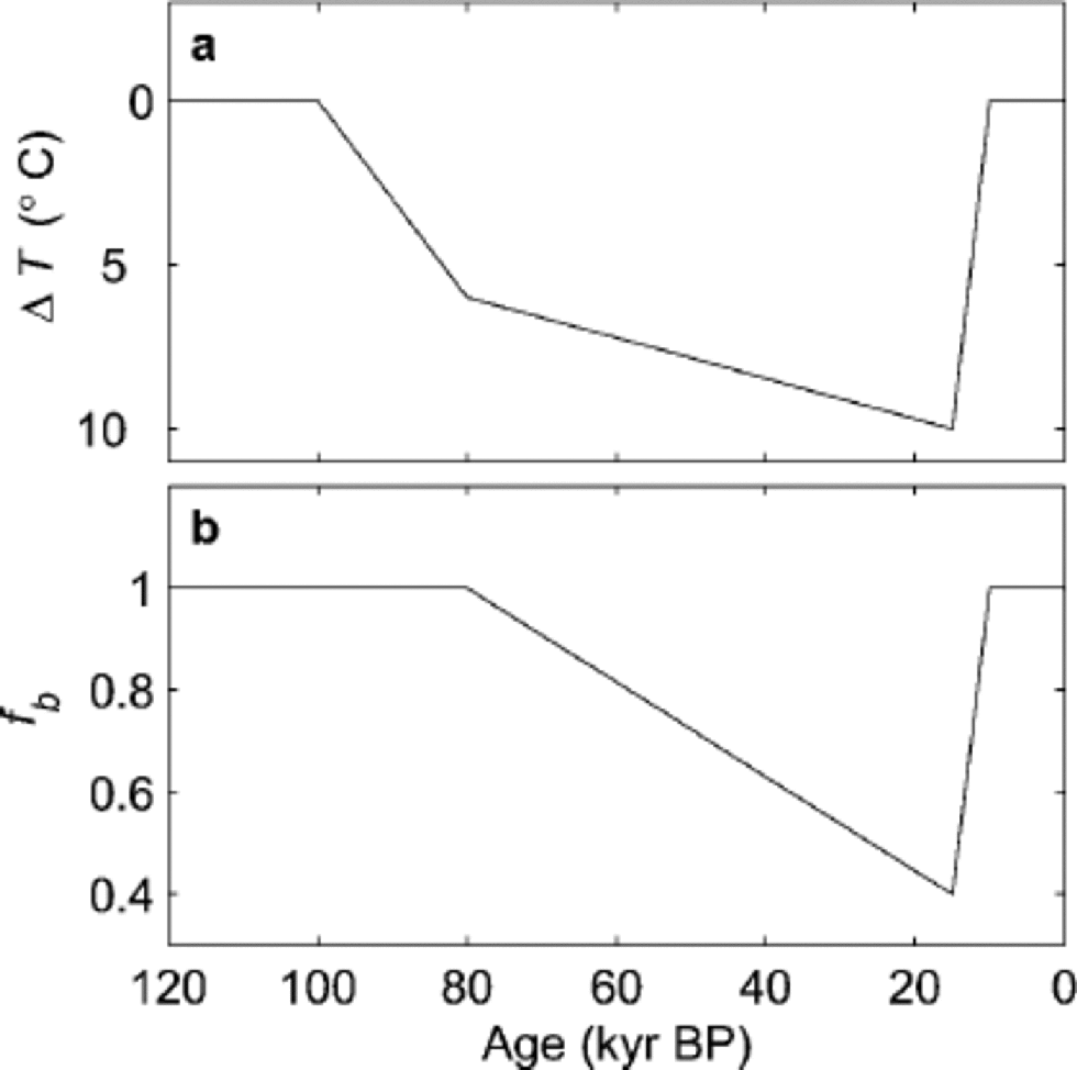
Fig. 8 Temperature (a) and non-dimensional accumulation-rate (b) histories used to simulate glacial climate variations for time-dependent temperature and depth–age calculations. We assumed that the local accumulation rate varied as ![]() and the temperature varied as
and the temperature varied as ![]() where superscript m denotes modern values given in Table 1.
where superscript m denotes modern values given in Table 1.
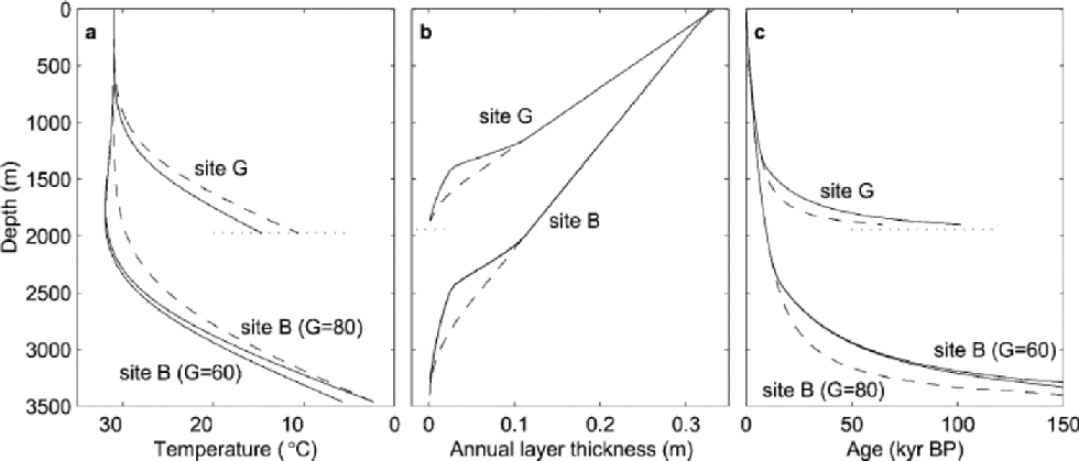
Fig. 9 Calculated profiles of temperature (a), layer thickness (b) and age (c) for sites B and G, which represent thick and thin end-member possibilities. the dashed curves are calculated using accumulation rate and surface temperatures held constant at their modern values. the solid curves show results using temperature and accumulation-rate histories given in Figure 8.
Table 2. Summary of thermal modeling for selected West Antarctic sites using the estimated surface temperature Ts and three assumed values for the geothermal flux. We give the maximum estimated basal temperature for sites that remain below the pressure-melting temperature Θ throughout the model run, and the 120 kyr mean melting rate for sites that reached melting at any time during the run
Depth–age scales and layer thickness
Calculating the depth–age relationship at these sites involves a time integral of the inverse of the velocity field (Equation (1)). We allow the accumulation rate ![]() to vary through time according to the history given in Figure 8. We performed two model runs with different values of basal melting rate
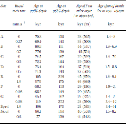
to vary through time according to the history given in Figure 8. We performed two model runs with different values of basal melting rate ![]() derived from our thermal modeling results that used the highest and lowest assumed values for geothermal flux. the depth–age scale and layer thickness profiles for sites B and G are given in Figure 9b and c, and the results for all sites are summarized inTable 3.
derived from our thermal modeling results that used the highest and lowest assumed values for geothermal flux. the depth–age scale and layer thickness profiles for sites B and G are given in Figure 9b and c, and the results for all sites are summarized inTable 3.
Table 3. Age and layer-thickness estimates for candidate sites. for each site, two different basal melting rates are assumed, corresponding to results of thermal modeling for lowest and highest values of geothermal flux
Discussion
The magnitude of the geothermal flux in central West Antarctica is the primary uncertainty in our thermal calculations; in particular, it determines whether basal melting conditions have occurred at these sites. Episodes of basal melting are probable at sites B and E and, to a lesser degree, at sites C and D. W. have considered geothermal flux values between 60 and 80 mWm–2, bracketing the value of 71 mWm–2 reported at Byrd (Reference Alley and BentleyAlley and Bentley, 1988). These values are appropriate for assumed Cretaceous rifting (Reference Doebbler and MorseDoebbler and others, 2001), though considering plume-related uplift in the mid- to late Cenozoic suggests values 50–250% higher (Reference Sclater, Jaupart and GalsonSclater and others, 1980) are possible. Further analyses of the radar-echo character may give some indication of past or ongoing basal melting. Analytic radar-echo strength discrimination methods for subglacial water detection (e.g. Reference Peters, Blankenship and MorsePeters and others, 2001) are not supportable with our incoherent radar data, since other interface characteristics in addition to the presence of water contribute strongly to the radar echo. A non-quantitative, ``smooth and bright’’ bed-echo criterion for basal water (e.g. Reference Siegert, Dowdeswell, Gorman and McIntyreSiegert and others, 1996) does identify several areas, including one near site A (Fig. 3), but these sites correspondonly weakly with sites that we expect from our thermal calculations to be the most likely candidates for melting. for example, the BST is almost certainly melting at the bed, but its bed echoes are neither smooth nor bright. Here we used the depth of an uppermost layer to infer accumulation rate; in a similar manner, we can look for anomalous dips of deep layers as an indication of substantial basal melting. Such analyses are ongoing; however, a preliminary inspection does not show any clear evidence for unexpected dips that would be indicative of substantial subglacial melting.
Currently, the Pine Island and Thwaites Glacier drainages on the Amundsen Sea side of the divide are undergoing significant temporal changes, and appear to be far from equilibrium (Reference Wingham, Ridout, Scharroo, Arthern and ShumWingham and others, 1998). the grounding line on the Ross Sea side has undergone approximately 1000 km of retreat since its most advanced stand of the Last Glacial Maximum (LGM) (Reference Stuiver, Denton, Hughes, Fastook, Denton and HughesStuiver and others, 1981; Reference Anderson, Shipp, Bartek, Reid and ElliotAnderson and others, 1992). Such large-scale configuration changes at the ice-sheet margins may also have caused the flow divide to migrate since the LGM. the extent to which the divide has migrated is unknown, and may depend critically on the profile of the ice sheet in the Siple Coast. If the ice was thick in the ``Ross Embayment’’ at the LGM, the divide may have shifted hundreds of km; however, if the profile was low in the ``Ross Embayment’’, or had insufficient time to reach a thick steady state, then the amount of migration could have been much less. (See Reference Steig, Alley and BindschadlerSteig and others (2001) for a recent review of WAIS thickness changes.) If the divide was previously much closer to the Ross Sea, then a site far from the current divide may be preferred over a site at the modern ice divide since the former could have been more divide-like and perhaps less influenced by the Amundsen Sea for much of its history. Such considerations are currently beyond the scope of our analyses.
Conclusions
The objectives for ice coring in West Antarctica guide evaluation of these seven sites. the primary advantage that ice-core climate records fromWest Antarctica offer over East Antarctic climate records such as the Vostok record (Reference PetitPetit and others, 1999) is improved temporal resolution of the recent past, afforded by the comparatively higher accumulation rate. Primary objectives for ice coring inWest Antarctica include establishment of the North–SouthHemisphere timing relationships for initiation of the last deglaciation and for millennial-scale climate events, such as Dansgaard–Oeschger events, the Younger Dryas and the Antarctic Cold Reversal, as well as their timing with respect to changes in greenhouse-gas concentrations. This objective requires good temporal resolution in ice-age ice. A drawback of higher-accumulation sites is their associated rapid downward flow, which transports relatively young ice rapidly to large depth, and simultaneously thins the layers by rapid vertical straining. As a result, for two sites that are otherwise comparable, the layers in approximately the lower half will tend to be thinner at the high-accumulation site. This motivated Reference Dahl-JensenDahl-Jensen and others (1997) to locate the NorthGRIP deep-drilling site in a region of North Greenland with lower accumulation than the GRIP and GISP2 sites, in the hope of locating a thicker Eemian sequence. In West Antarctica, it suggests that we may want to avoid sites with the highest accumulation rates, unless the objective evolves into collection of the highest-possible-resolution Holocene record.
We find that the accumulation rate is similar among the divide and near-divide sites that we consider and ice thickness is the dominant factor in determining age resolution for a recovered climate history. Because vertical strain rate scales inversely with ice thickness, temporal resolution, especially in the glacial-period ice, increases with increasing ice thickness. This leads us to prefer the thick-ice sites to the thin-ice sites. Divide sites such as B, and flank sites such as E are most suitable; intermediate-thickness sites such as A, C and D rank second, and thin ice sites such as F and G are least likely to offer a climate record that will achieve the scientific objectives for deep drilling in West Antarctica. These rankings are robust to our uncertainty over the potential for basal melting.
Core quality is an additional consideration. Ice in the depth range 400–1600m contains occluded air bubbles in which air pressure can exceed the fracture strength of ice. This ice is brittle, and, as a result, core quality is often compromised. (In ice deeper than about 1600m, trapped air has been converted to clathrate forms.) In low-accumulation-rate or shallow-ice areas, the brittle-ice zone can include Ice Age ice in which we are interested. We expect this to be the case for the thin-ice sites F and G (Table 3), and these sites should be avoided.
Our analysis shows that the thick-ice sites B and E along the Ross Sea/Amundsen Sea ice divide of West Antarctica are most attractive for ice coring given age-resolution and core-quality considerations. A core recovered from there will offer a climate record substantially different from that of the Byrd core. If a drilling capability exists to complete a core to bedrock at any of our targeted sites, then a preference for these thickest-ice sites would be scientifically unsupportable only if the primary objective is to obtain the oldest possible interpretable ice (e.g. to address the onset history of the ice sheet itself).
Acknowledgements
This work was supported by U.S. National Science Foundation (NSF) grants OPP-9615251 and OPP-9726500 to the University of Texas and OPP-9615169 to the University of Washington. the aerogeophysical surveys were carried out by the University of Texas Institute for Geophysics (UTIG) operating under NSF/OPP-9319379. We thank the UTIG scientists, engineers and students who participated in collection and reduction of these data, including S. Kempf, M. Peters, K. Najmulski, T. Richter, J. Holt and G. Tsoflia. as well as the personnel of Ken Borek Air Ltd, Expedition Computing Inc., the Geophysics Branch of the U.S. Geological Survey and Lamont–Doherty Earth Observatory. We also thank UTIG undergraduate research associates J. Doebbler, A. Mielke,M. Mitchell and A. Barr. for assisting in reducing these radar data and for suggesting the name ``Mount Resnik’’ in memory of the lost Challenger astronaut. Much of this work was stimulated by discussions with members of the U.S. ice-coring community, including K. Taylor, P. Mayewski and D. Bromwich.


