


Introduction
The problem of fabric development in ice sheets has recently been addressed. Among the models proposed to describe the anisotropic behaviour of polar ice and the evolution of its strain-induced anisotropy, micro-macro models aim to take into account the microstructural processes acting at the grain scale. During creep of polycrystalline ice, each grain of the polycrystal experiences a non-homogeneous deformation. These heterogeneities are a consequence of the strong viscoplastic anisotropy of the ice single crystal which deforms mainly by dislocation glide in the basal planes (Reference Duval, Ashby and AndermanDuval and others, 1983). This characteristic behaviour leads to strain incompatibilities between grains with different lattice orientations and therefore influences the macroscopic behaviour of the ice polycrystal.
The development of a constitutive model for polar ice, based on a micro-macro approach, requires a microscale constitutive model as an input. The reliability of such a model will be assured if the essential physical mechanisms involved in the deformation are taken into account. In principle this should be done by modelling the ice single crystal and the grain-boundary behaviour. However, in practice this can be done by using a more phenomenological model of grains (i.e. including the description of single crystal behaviour and of its interaction with grain boundaries) involving a number of internal variables related to physical mechanisms acting at a smaller scale. This model then has to be fitted against experimental data in a more or less direct manner (usually the grain model is fitted through the comparison of the macroscopic model with experimental or field data).
The aim of the present study is to improve our understanding of the viscoplastic deformation of a grain by identifying some of the mechanisms involved during the deformation.
Experiments
To study the deformation inside the grains, and strain incompatibilities arising between grains, compressive-creep experiments on thick sections of ice were carried out with a specially designed testing machine located in a cold room at –10±0.1°C (see Fig. 1). The specimens were rectangular plates 210 mm high, 140 mm wide and 8 mm thick. Two types of specimens were studied:
Type-A specimens consisted of a circular monocrystalline inclusion embedded in a fine-grained isotropic matrix. The diameter of the inclusion was 30 mm and the size of the grains of the isotropic matrix was about 1 mm. The inclusion was cut from a single crystal so that its c axis lay in the plane of the specimen. It was then stuck to a metal plate and surrounded by calibrated grains of ice (0.64 mm <φ< 1.6 mm) which were saturated with water. After freezing on a cold table, the specimen was milled to obtain a rectangular plate so that the inclusion c axis had a desired orientation (within ±2°) with respect to the longest side of the rectangle. Experiments were carried out with three different initial orientations of the inclusion c axis with respect to the compression axis, 45°, 25° and 0°, and with two different compressive stresses of 0.5 and 1 MPa.
Type-B specimens were made like type-A specimens but the rectangular type-A plate containing the inclusion was used as a seed to grow columnar S2 ice. The type-A seed was stuck on the metal bottom of a laterally insulated tank which was then placed on the cold table. The growth of ice led to one large column corresponding to the initial monocrystalline inclusion surrounded by smaller columnar grains (about 5–10 mm in diameter, the increase in grain diameter being due to preferential growth of the initially well-oriented grains with c axes in the plane of the seed). The resulting inclusion was about 50 mm in diameter, with a very irregular boundary, and the matrix was heterogeneous compared to that of type-A specimens. Only two type-B specimens with the same orientation of the inclusions (45° from the compression axis) were tested under 0.5 MPa.

Fig. 1. Schematic drawing of the testing device.
This special specimen design was adopted to avoid direct testing of a single crystal. Due to the very strong anisotropy of ice the interpretation of mechanical tests on ice single crystals is extremely difficult since the interaction between the crystal and the testing device is always very influential and impossible to avoid. Embedding the crystal into a homogeneous and isotropic matrix led us to believe that, with a proper choice of the inclusion diameter with respect to the dimensions of the specimen, the boundary conditions could be applied far enough away to obtain a relatively uniform state of stress inside the inclusion, according to Reference EshelbyEshelby’s (1957) solution.
Plane strain was imposed on the specimens by means of two glass plates in contact with the two larger faces. Constant loading was applied through a horizontal blade of the same thickness as the specimen (see Fig. 1). The specimens were loaded progressively to avoid cracking. During the test, the displacement of the upper loading blade with respect to the lower fixed platen was measured with an accuracy of about 5μm. Photographs of the specimen were taken during each test to follow the evolution of the deformation. The contrast between the inclusion and its surrounding matrix was enhanced by using cross polarizers placed either side of the specimen.
The duration of the tests varied from 3 days for a compressive stress of 1 MPa to 45 days for a stress of 0.5 MPa, corresponding to a total strain of 20% and about 16% respectively
Experimental Results
Creep tests with type-A specimens
Figure 2 shows a typical sequence of photographs taken during compression of a type-A specimen. The inclusion was initially circular and oriented at 45° to the compression axis. As the total strain experienced by the specimen increased the inclusion transformed into an ellipse which was constantly flattening (see Fig. 8).

Fig. 2. Evolution of the shape of the inclusion and rotation of the basal planes for specimen A45-1. Compressive creep stress 1 MPa, c axis initial orientation 45° from the vertical compression axis. The superimposed pattern is 20 mm wide.
At the beginning of loading, both basal-slip bands and blurred bands normal to the basal planes arose simultaneously across the inclusion (see Fig. 2b). Slip bands appeared as an alternation of well-defined coloured stripes parallel to the direction of the basal planes, about 1mm wide. The bands normal to the basal planes were less numerous, approximately 2–5 mm wide and much less marked than the slip bands. After a certain amount of deformation (about 1 % total strain) they tended to disappear while the coloured slip bands tended to transform into well-defined dark slip lines. These unstable blurred bands looked similar to the unstable kink bands reported by Reference Wilson, Burg and MitchellWilson and others (1986). They could be explained by rearrangement of the dislocations at the very beginning of loading which would lead to the regular pattern shown in Figure 2b. Although most of them disappeared with increasing deformation one or two remained stable in the far ends of the elliptical inclusion. However, they did not transform into lines of strain localization but remained faint but visible. The same phenomenon was observed with all type-A specimens.
As shown in Figure 3, the activated basal planes were homogeneously distributed in the single crystal (the spacing between two adjacent slip lines varied from 0.1–0.7 mm). Even under a compressive stress of 1 MPa, an inclusion well-oriented for basal glide, deformed up to 50% (this total strain being estimated as the ratio of the initial radius of the inclusion to the length of the long axis of the ellipse), did not show any visible glide system or strain localization except for the basal planes.

Fig. 3. Inclusion initially well-oriented for basal glide after 8% total strain (σcomp =0.5 MPa ).The activation of basal glide gave rise to localized slip lines which appear as dark parallel lines in the inclusion (specimen A45-2).
During its deformation, the shape of the inclusion was close to an ellipse, corresponding to the shape which would be obtained for a uniform strain field. During the test the basal planes rotated towards the direction perpendicular to the compression axis (see Fig. 7). The inclusion long axis rotated in the same direction as the basal plane, but not at the same rotation rate.
Some recrystallization took place at the inclusion boundary, particularly at the narrow ends of the ellipse. This form of strain accommodation was probably due to the discontinuous conditions at the matrix-inclusion interface, between the fine-grained matrix which can be considered as isotropic and the anisotropic single crystal with a single easy-glide direction. Dislocation glide in the basal planes in the inclusion leads to pile-ups which increase the dislocation density and the stored energy near the boundary, allowing the nucleation of new grains.
As shown in Figure 4, after removal of the load and after a 15 day recovery period at –10°C, grains appeared to grow at the matrix-inclusion boundary. This growth occurred partly inside the inclusion, with a lattice orientation which seemed to be symmetric with respect to the direction of the inclusion basal planes (at 22 ± 2 ° and –22 ± 2 ° in Fig. 4). This growth, which is a consequence of the local conditions between the inclusion and the matrix grains, was not uniform in the thickness of the specimen (owing to the relatively small grain-size of the matrix, 8 to 10 grains of the matrix were in contact with the edge of the inclusion). In the matrix, post-recrystallization occured gradually, with grains whose size was about three to ten times larger than the initial size, for specimens deformed up to 15%.

Fig. 4. Recrystallization at the boundary between the matrix (right) and the inclusion (left) for specimen A45-1 (σ comp =1 MPa).
The experiments performed on inclusions with an initial orientation of 25° led to the same qualitative results. The strain-rate was lower for the specimen as well as for the inclusion and the deformation inside the inclusion still seemed to be homogeneous despite being less-favourably oriented. The same observations were done during the test with regard to the rotation of the basal planes, the change in the shape and orientation of the inclusion and recrystallization.
An experiment on an inclusion with its basal plane perpendicular to the compression axis showed no visible activation of basal glide. The deformation of the inclusion was not measurable and in this configuration the matrix was observed as flowing around a rigid circular inclusion.
Creep tests with type-B specimens
Owing to the process of their fabrication, type-B specimens exhibited a matrix-inclusion boundary with an irregular geometry. Therefore the stress field inside the inclusion should not be uniform. Nevertheless, at the beginning of the tests the inclusion presented a homogeneous repartition of basal-slip lines and of larger blurred bands perpendicular to them (see Fig. 5b). Contrary to tests performed with type-A specimens, the heterogeneity of the deformation increased during the test. The bands formed perpendicular to the basal planes were more unstable, appearing and/or disappearing with time, and some of them led to the formation of bending bands and narrow kink bands which appeared as neat dark lines to the naked eye. Bending bands were characterized by a progressive change of the crystallographic orientation of the lattice from one side to the other side of the band which delimited two areas of the inclusion with different crystallographic orientations (see band I in Fig. 5c and d). They can be considered as thick walls of dislocations associated to crystal polygonization.

Fig. 5. Evolution of the shape of the inclusion and development of the strain localization in specimen B45-1. Compressive creep stress 0.5 MPa, inclusion c axis initial orientation 45° from the vertical compression axis. The superimposed pattern is 20 mm wide.
On the other hand, kink bands delimited two areas of the crystal with the same basal-plane orientations. Inside the kink band the basal planes remained parallel to each other, but at high angle from the adjacent areas, and the change of lattice orientation was concentrated at each boundary of the band (see Fig. 6). These features acted as shear bands characteristic of strain localization. Kink bands shown in Figure 5c and d (band II) are 0.5–1 mm wide.

Fig. 6. Kink band in a deformed type B specimen. The marked and kinked dark lines are the basal planes.
During the tests performed on inclusions initially at 45° from the direction of compression, the orientation of the kink bands changed by a rotation with a sign opposite to the rotation of the basal planes. Thus the kink bands, initially formed perpendicular to the basal planes, did not remain perpendicular to the basal planes as the deformation of the specimen increased, but rather remained almost symmetric to the direction of the basal planes with respect to the direction of compression (which is consistent with a shear-band behaviour). Then, the rotation velocity of the kink band was opposite to the basal-planes rotation velocity outside the band (in the global frame). The rotation rate of the basal planes inside the kink bands with respect to the outside basal frame was twice the rotation rate of the kink-band boundaries in the same frame.
The first kink bands appeared near the ends of the elliptical inclusion and tended to separate the asperities from the main body of the inclusion to preserve a more equiaxed shape (see band III of specimen B45-1, Fig. 5d). These kink bands were very stable and after a high total strain (about 7%) transfomed into a boundary between the inclusion and sub-grains with high disorientations (up to 10°) (see Fig. 5c).
Other kink bands formed in the body of the inclusion at the same time. These were initiated at high singularities of the matrix-inclusion interface and propagated inside the inclusion during creep. They were often unstable, softening and disappearing with time. However, when the basal-plane orientations reached about 55–52° from the compression axis, other kink bands appeared, becoming more and more marked until the test was stopped (see band II, Fig. 5). The observed lattice disorientation inside the kink (Fig. 6b) was 60° at the end of the test (total strain 9.8%).
Concerning the coarse-grained matrix, intense dynamic recrystallization was observed from the beginning of the tests. This migration-recrystallization regime is a characteristic of tests performed under a relatively high stress level at high temperature. The first signs were observed at practically all the grain boundaries which transformed from very sharp straight lines upon loading into blurred widening zones after a small amount of deformation (less than 1%). After larger deformation only a minority of the initial grains were still recognizable. This evolution can be seen in Figure 5a, b and c.
Discussion
Rotation and bending of the basal planes during creep of polycrystalline ice were observed by Reference Wilson and ZhangWilson and Zhang (1994) and Reference Azuma and HigashiAzuma and Higashi (1985). Kink bands were observed by Reference Wilson, Burg and MitchellWilson and others (1986) and Reference Manley and SchulsonManley and Schulson (1997) during plane-strain compressive tests on isotropic ice and SI ice respectively. Reference Wilson, Burg and MitchellWilson and others (1986) observed that the occurrence of kink bands was always preceded by slip on the basal planes. According to these authors these kink bands were unstable, able to change in shape and orientation and to disappear because of grain-growth processes. Kink bands in other materials with hexagonal symmetry, such as zinc and cadmium, have also been observed in single crystals submitted to compression in a direction close to perpendicular to the c axis (Reference HoneycombeHoneycombe, 1984).
Our observations suggest that the occurrence of the kink bands is closely related to stress concentrations at the matrix-inclusion interface. This is particularly visible on type-B specimens: owing to the S2–columnar type of the matrix and to the large size of its grains, there was only one grain in contact with the inclusion along a line perpendicular to the plane of the specimens (i.e. a generator of the cylindrical inclusion). The phenomena observed in the inclusion of type-B specimens were also observed in the coarse grains of the matrix, which seems to indicate that there is no scale effect. For type-A specimens, the number of grains in contact with the inclusion along a generator was between five and ten (the inclusion was 8 mm thick). As a consequence, the stress concentrations at the inclusion-matrix interface were smoother and the deformation of the inclusion was more homogeneous. On the other hand, owing to the large number of grains in the thickness of type-A specimens, observation of the matrix grains was not possible, but there is no reason why the deformation in these grains should be homogeneous. Thus the difference in behaviour of the inclusions of the two types of specimens does not lead to the conclusion that crystal size could have an impact on the ice-deformation rate. In fact, the two types of specimens showed similar minimum strain rates (about 5xl0–8 S–1 under a compressive stress of 0.5 MPa) for a strain close to 1%, which is in agreement with Reference Duval and le GacDuval and le Gac’s (1980) and Reference JackaJacka’s (1984) results.
The disappearance or preservation of the bands normal to the basal planes could be explained by the movement of dislocations in relation to the resolved shear stress acting on the basal planes. Since the velocity of the basal dislocations is a linear function of the resolved shear stress on the basal plane (Reference Fukuda, Hondoh and HigashiFukuda and others, 1987; Reference Hondoh, Iwamatsu and MaeHondoh and others, 1990; Reference Shearwood and WhitworthShearwood and Whitworth, 1991), the high density of dislocations in the kink band could easily be decreased by the migration of the kink-band boundaries when the inclusion is well- oriented for basal glide. This would induce a widening of the kink band and consequently a decrease of its internal disorientation. Another complementary explanation for the appearance and disappearance of unstable kink bands might be successive phases of build-up of stress concentrations at the matrix-inclusion boundary followed by stress relaxation owing to dynamic recrystallization. This is supported by the absence of stable shear bands in type-A specimens and by the fact that the stable shear bands observed in type-B specimens are associated with hard grains at the matrix-inclusion interface which did not exhibit any tendency to recrystallize (see Fig. 5c and d). After a deformation sufficient to induce a significant rotation of the inclusion basal planes, the corresponding reduction of the resolved shear stress could be such that recovery by dislocation glide in the basal planes of the inclusion becomes too slow to allow the migration of the kink-band boundaries. Then the level of stored energy inside the kink band could be decreased or made stationary by internal shearing. These assumptions need to be assessed by supplementary tests on inclusions with an irregular boundary different initial orientations and under higher compressive stress.
The conditions of the experiments (monocrystalline inclusion, plane-strain condition) are obviously far from the in-situ conditions which prevail in glaciers or ice sheets. However, these experiments are expected to provide some indication of the mechanisms involved in the deformation of ice, notably as regards the grain-to-grain interaction which is a crucial matter for modelling the macroscopic behaviour of anisotropic polar ice. Interpretation of the experimental results (Figs 7 and 8), in terms of a constitutive model for the grain, is given in more detail by Reference Mansuy, Meyssonnier, Philip, Hutter, Wang and BeerMansuy and others (1999).
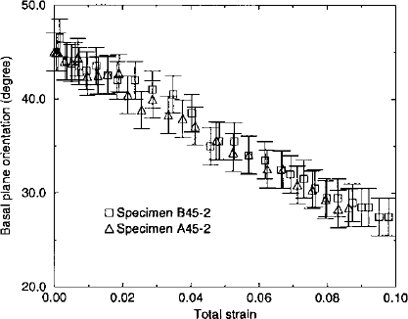
Fig. 7. Observed rotation of the basal planes of the inclusion vs total strain for two specimens with initial basal-plane orientation at 45° from the compression axis σcomp = 0.5 MPa).
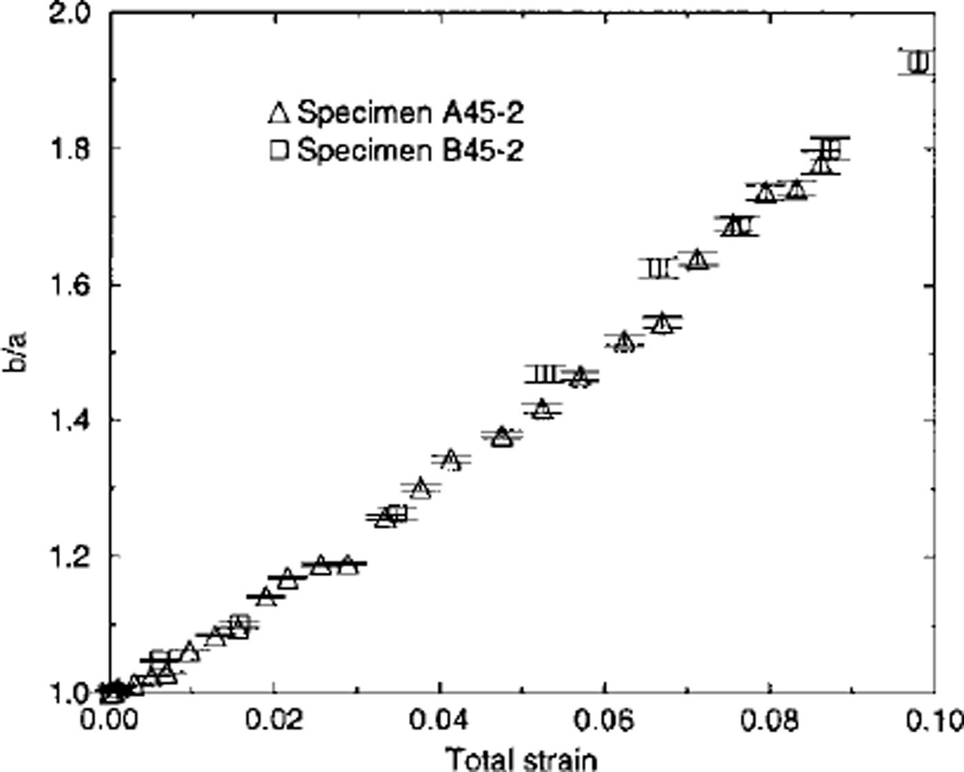
Fig. 8. Observed flattening of the shape of the inclusion vs total strain for two specimens with initial basal-plane orientation at 45° from the compression axis (σcomp = 0.5 MPa).
Conclusion
The compressive-creep tests carried out on two types of ice specimen containing a monocrystalline inclusion allow a first approach to the phenomena which can lead to strain localization in a polycrystal of ice.
For initially circular inclusions embedded in a finegrained ice matrix, deformation in the inclusion did not exhibit any other strain localization than that associated with basal glide. Deformation at the inclusion scale was then very homogeneous (in agreement with results from finite-element modelling by Reference Mansuy, Meyssonnier, Philip, Hutter, Wang and BeerMansuy and others (1999). However when the matrix-inclusion boundary exhibited singularities, caused by the presence of coarse grains, strain heterogeneity occurred in the inclusion (although it was "well-oriented" at 45° from the compression axis). Two types of kink bands were observed to form progressively. An unstable type, consisting of faint bands crossing the inclusion, formed perpendicular to the basal planes. These bands were observed with both types of specimen tested. The other kind of kink band evolved into stable shear bands or into larger bending bands which provided additional degrees of freedom for the deformation. These were observed only on type-B specimens exhibiting marked matrix-inclusion singularities.
Further experimental work is needed to understand and quantify the conditions under which grain-to-grain interactions can lead to stable strain heterogeneity in deforming ice in order to improve the physical modelling of the mechanical behaviour of ice.
Acknowledgements
The financial support from the European Commission (contract No. ENV4-CT95-0125 "Fabric Development and Rheology of Polar Anisotropic Ice for Ice Sheet Flow Modelling"), the Centre National de la Recherche Scientifique (Programme INSU-Géomateriaux, 97GEOMAT02) and from the Université Joseph Fourier Grenoble-I are gratefully acknowledged. The authors wish to thank D. Dahl-Jensen and Li Jun for very helpful comments and discussion.


