


Introduction
Gaining access to basal ice and the subglacial environment of large ice sheets is of great scientific interest. In addition to providing samples to examine bedrock geology, samples of basal ice and direct observation of the subglacial environment yield information about ice-sheet/bedrock interactions and how this zone influences the overlying ice-sheet dynamics (e.g. Reference Tison, Petit, Barnola and MahaneyTison and others, 1993). Sampling from this zone also provides a rich paleo-environmental archive for many applications including cosmogenic-isotope and luminescence exposure dating, and biological studies including ancient DNA (Reference WillerslevWillerslev and others, 2007). In the central regions of large ice sheets, direct observation of basal ice environments is rare, but can be gained via the deep boreholes created by ice-core drilling. However, the basal material lying between clean meteoric ice and the bedrock is notoriously difficult to drill (Reference TalalayTalalay, 2013). Ice located in the immediate vicinity of the bedrock interface is often loaded with rock and sediment particles of various sizes and concentrations and/or is near the pressure-melting point.
At the NEEM (North Greenland Eemian Ice Drilling) site in northwest Greenland, deep ice-core drilling was declared terminated in July 2010 at 2537.36 m depth, when no further penetration was possible with the available equipment (Reference Popp, Hansen, Sheldon and PantonPopp and others, 2014). A rock embedded directly in the path of the drill head halted penetration, and efforts to dislodge or cut through this rock using standard ice cutters mounted on the NEEM version of the Hans Tausen (HT) drill resulted only in destroying the cutters. However, this depth was not assumed to be the bedrock interface itself. The final ice cores contained a significant amount of basal ice-sheet material, including silty ice and some small stones (Fig. 1), and it seemed probable that more layers of banded silty ice and an interval of rock/ice mixture remained before the actual bedrock interface.
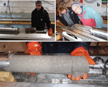
Fig. 1. The final cores collected at NEEM approaching the obstructions at 2537.36 and 2538.10 m depth were drilled with the Hans Tausen drill mounted on the NEEM deep-drill electronics, motor and gear sections. Banding silty and sediment-laden ice can be seen in (a, b). The chips also contained sediment material (c). The cores pictured were collected in 2011 with ice cutters with carbide inserts (Fig. 4). Similar cores with standard ice cutters were obtained to close the 2010 season.
Targeted drilling campaigns continued in the NEEM borehole for part of each of the 2011 and 2012 field seasons. The goal was to penetrate beyond the obstruction in the borehole and into the bedrock itself if it could be reached. To maximize the chance of penetrating further, two approaches were considered. First, we mounted reinforced cutters of carbide steel and cutters with modified geometries onto our standard ice-coring head on the HT drill. Already, our standard cutters had succeeded in penetrating some coarse material, so these additional reinforcements to the cutters on the ice-core drilling head seemed promising, at least for a rock/ice mixture. Second, we adapted a conventional rock-drilling unit with a smaller outer diameter (o.d.) to replace the lower part of the ice-core drill below the motor section (51mmo.d. vs 132 mm with the NEEM version of the HT drill). With this rock drill we intended to bypass the obstacle if the attempts with the reinforced ice cutters failed, penetrate ice-embedded rocks and rock fragments along the way, and then use it to drill straight into pure rock further down. Because we expected an ice/rock mixture before reaching the bedrock interface, we hoped that combining these two approaches would compensate for the facts that the ice-core drill head was not particularly well suited for drilling in rocks, and that the rock-drill head was not particularly well suited for drilling through ice.
Status of the Bottom
A major drilling challenge when collecting basal ice-sheet material at NEEM was that the status of the bottom was unknown. Even though warm-ice drilling near the base at NEEM had been relatively trouble-free to this point (Reference Popp, Hansen, Sheldon and PantonPopp and others, 2014), if many more meters were required to reach the bottom, liquid water could increasingly interfere with drilling as temperatures approached the ice pressure-melting point. At 2537 m the ice temperature was −3.4°C, and while we tried to maintain a pressure-balanced borehole by adjusting the drill fluid level during drilling, the pressure at the base of the borehole was up to 0.1 MPa less than the pressure exerted by the surrounding ice sheet at this depth. This under-pressure would therefore allow melt-water, if present, to enter the borehole, rather than force borehole drill liquid into the subglacial environment.
It was also unclear from the available information how many more meters of ice and debris remained below the bottom of the existing borehole before the actual bedrock interface. Interpretations of radio-echo sounding and borehole temperature profiles, as well as sonar experiments near the bottom of the borehole, gave estimates ranging from tens of centimeters to tens of meters before the bedrock interface would be reached. Furthermore, we could only guess at the character and composition of the debris-laden ice, the size of the rocks and rock fragments we might encounter, and how banded the sediment/rock/clear-ice mixture would be in the remaining depths. In an attempt to ‘see’ the bedrock, the sonar experiments were carried out at 2496.33 and 2533.12 m, i.e. 41.03 and 4.24 m above the 2010 final depth. For this purpose an experimental borehole instrument was constructed at the University of Bern, consisting of a battery-operated electromagnetic pinger (gong type) that emitted signals at a rate of ∼1 s−1 with center frequency of ∼5 kHz where reflections are recorded with a piezo hydrophone. The analog signal is superimposed as current signal on the power supply of the hydrophone and digitized and recorded at the surface. Interpretation of these signals was inconclusive, but suggested that the bedrock could be <2 m away from the bottom of the borehole. This turned out not to be the case, and the observed signals may have come from a heavy silty layer or resulted from the fact that the dirty ice was simply too opaque to resolve the actual bedrock/ice interface. Nevertheless, based on the information at the time, we operated under the assumption that <2 m remained, and preparations and expectations were originally focused on this depth.
Drill Set-up
Hans Tausen drill with reinforced ice cutters
As we approached the bedrock at NEEM in late July 2010, the HT drill configuration was set in a mode deemed most favorable for drilling in the warm ice, during which the first cores containing silty ice and small rocks and rock fragments were collected with no special consideration given to the cutters or drilling process with respect to the coarse materials we were to encounter (Figs 1 and 2). In this set-up, the long barrels of the NEEM drill were replaced with the lower part of the HT drill with its 1.6m core barrel and 1.6 m chip chamber (Reference Popp, Hansen, Sheldon and PantonPopp and others, 2014). These were mounted to the deep drill electronics, computer, motor and gear sections to allow the same fine control and monitoring of the cutting process at depth that we had with the long drill. In addition to our standard hardened-steel ice cutters (Böhler S390PM for Swiss-made cutters; Uddeholm Viking Steel 54-56 HRC for Danish-made cutters), step cutters (cutters with partial kerf; Reference Zagorodnov, Thompson, Ginot and MikhalenkoZagorodnov and others, 2005) were also mounted. Step cutters were beneficial in warm ice because they produced coarse chips that moved efficiently away from the drill head without packing, and required less power per revolution to cut the same amount of ice (Reference Popp, Hansen, Sheldon and PantonPopp and others, 2014).
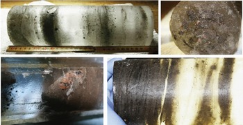
Fig. 2. Four images of the final 98 mm diameter ice cores drilled with the NEEM version of the HT drill equipped with cutters with carbide inserts (see Fig. 4) containing banded clear ice, fine- and coarse-grained sediments, and embedded stones up to 2 cm in diameter.
While the standard and step versions of the ice cutters proved capable of drilling through some rock fragments and other coarse material, they were destroyed in the process (Fig. 3). Thus, two types of reinforced ice-cutter geometries with tungsten carbide were created in an attempt to improve performance. One approach was to mount tungsten carbide inserts which would act as step cutters mounted on the head of the HT drill (Fig. 4). Placed on cutter bodies based on the normal cutter geometry, these inserts had been shown to be capable of penetrating gneiss and granite in a controlled manner in the workshop with a drill press. The cutter sets made for the carbide insert were designed to create a borehole diameter of 126mm, 6mm less than the nominal borehole diameter at NEEM. This would improve the likelihood of drilling past the obstacle sitting toward the outer edge of the existing borehole while at the same time producing fewer chips, which is desirable in warm-ice drilling conditions. A second approach was to create a set of cutters with carbide-reinforced tips welded directly onto the cutting edge of standard steel cutter bodies with full kerf for each of the three cutters in a set. In all cases these cutters produced the nominal 98mm diameter ice core.
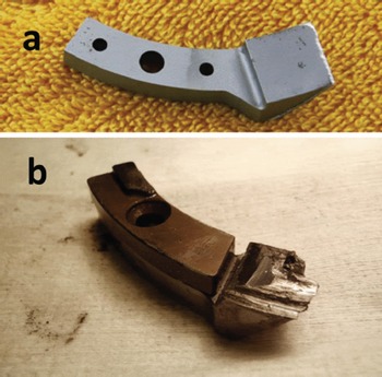
Fig. 3. Destroyed cutters after contact with coarse material and stones. (a) A standard ice cutter showing erosion at its cutting edge. (b) A destroyed version of modified step cutters mounted with a carbide cutting insert (Fig. 4), which has been snapped off its mount and otherwise completely worn down after contact with embedded rock obstructions in the borehole.
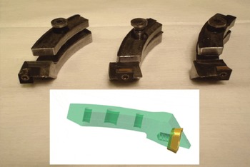
Fig. 4. Cutters with carbide cutting inserts were mounted on the HT drill head in an attempt to penetrate past the obstacle at 2537.36 m. These cutters succeeded in collecting an additional 0.74 m of ice cores in 2011, before meeting another impassable obstruction. In 2012 these types of cutters came up completely destroyed after one attempt downhole. It was later discovered that despite their destruction, they had been slowly grinding away at the stone that had been blocking penetration (Fig. 11).
Adapted rock drill
A small-diameter conventional rock drill with core-catching collar ring was adapted to be connected to the upper sections of the NEEM deep drill (Fig. 5). The same rock drill had been used previously to collect bedrock at the Greenland Ice Sheet Project 2 (GISP2) drilling site, but with different replaceable cutting heads (Reference Wang, Collins and HuangWang and others, 1994). The rock-drill bit itself is composed of diamond cutting tips on a semi-round crown which produces a 51mm diameter borehole and a 33mm diameter core (Fig. 5). The cutting head could be threaded onto any number of 1.5 m long extension rods to allow deeper and deeper access as the 51 mm borehole was extended to greater depths into which the upper end of the drill would not fit. Centering rings were constructed and mounted to support the long shaft as it rotated in the 132 mm borehole and found its way into the extended narrow borehole. The lowest of these centering rings was not fixed to the shaft and could slide upwards as the extensions continued deeper into the narrow borehole (Fig. 5).
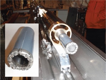
Fig. 5. Rock-drill head with diamond tips (inset) mounted on the NEEM tower, driven by the NEEM deep-drill motor and gear sections. Brass centering rings were mounted to center the rock drill in the 132 mm diameter NEEM borehole. Extension rods added in 1.5 m sections were added to reach a final depth 7.1 m below the obstruction at 2538.1 m.
Having adapted this rock drill to our drill system without modifying the drill motor and gear sections, we were advised that it would be suboptimal for the desired weight-on-bit (WOB) or rotation speed characteristics for efficient cutting. For such a system rotation, speeds of >500rpm (Reference Wang, Collins and HuangWang and others, 1994) and WOB exceeding 200 kg (personal communication from Geo Engineering A/S, 2010) were recommended. By not meeting these criteria, we ran the risk that the cutting head, rather than biting into stone, would simply skate on the rock surfaces, resulting in premature deterioration of the cutting edges. The rotation speed was fixed at 80 rpm by the motor and gear sections we had available. However, to increase cutting efficiency we were able to add up to three dead-weight sections of 70 kg each above the motor section to increase the weight of the drill. When cutting we could apply up to 240 kg on the bit, which was the full weight of the drill including the extra dead-weight sections in the buoyant liquid column. Under these circumstances a new drill head would last up to about ten runs in the sediment/rock/ice mixture before being replaced. We gained confidence in this set-up with a test drilling at the surface into granite which showed the drill was able to penetrate at a rate of ∼1 cm in 2 min.
For drilling in the fluid-filled borehole the design and implementation of a suitable pumping system to circulate liquid at the cutting head was also required. The pump section was created around a commercially available orbital motor (Sauer-Danfoss OMM50), where the turning motor functioned in this case as a hydraulic pump (Fig. 6 inset). The motor’s rotation was driven by the drill motor attached via a gear designed to turn the motor three times faster than the rotation of the drill tube (Fig. 6). The upper part of the pump gear section was constructed to be mounted onto the rotating bearing at the lower end of the deep-drill motor and gear section, which, in turn, turns the pump gear and the hydraulic pump itself. The connection to the NEEM deep-drill motor section is essentially made in the same way that the hollow shaft is mounted inside the chips chamber in normal ice drilling with HT-type drills (Reference JohnsenJohnsen and others, 2007), where it hangs on three engaged spring-loading screws. Given the nominal rotation speed of 80 rpm available with the existing drill motor and a pumping capacity of 50 mL rev−1 we could expect a maximum flow of ∼12 Lmin−1. To protect the pump from fine grit and coarse particles created during drilling, the entire pump section body was wrapped in a fine-mesh filter before each run (Fig. 7), and the debris trapped in the filter could also be collected as sample.
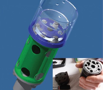
Fig. 6. The pump and gear section for the adapted rock drill. The upper part of the gear section is constructed to be mounted onto the rotating bearing at the lower end of the deep-drill motor and gear section, which, in turn, turns pump gear (blue) and the hydraulic pump (internal mechanism view shown inset at lower right) which is housed inside the green section. Depending on the orientation at which it is mounted, the flow direction can be reversed. With the speed of the outer toothed wheel set by the drill motor, the pump gear was designed to turn three times as fast as the rotating drill shaft. The large holes in the green section are lined with a fine-mesh filter to protect the pump from the rock dust and sediment produced during cutting while allowing liquid to flow through the pump.
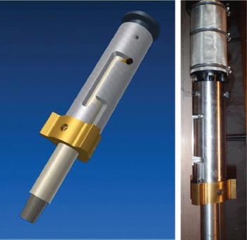
Fig. 7. Bayonetted coupling between the pump section and extension rods of the adapted rock drill. The pump section at the top of the right photo is covered in a fine-mesh filter that was replaced after each run when it became coated in sediment particles. The extension rods threaded onto the lower part of the bayonet coupling. The bayonet could be used to provide a hammer effect when making a hard-core break, or be released if the drill head was stuck, thus recovering all of the upper parts of the drill sonde. Fortunately this never needed to be used in the rock drilling at NEEM.
Below the pump, a connection piece to the drill head and extension rods was designed to mimic the bayonetted ‘Super Banger’ connection used in the normal operation of HT-type drills (Fig. 7). With initial concerns that our cable might not be strong enough to break a rock core with a static pull, this feature allows the full weight of the drill to act as an efficient hammer giving a sharp impact to assist in breaking the core. As with normal ice-drilling operations it also allows the rock-drill head (and its extension rods) to be detached downhole in order to recover the rest of the drill if the drill becomes stuck.
Collecting Basal Ice-Sheet Material and Drill Performance
As the NEEM borehole approached the bedrock interface in 2010, penetration problems during drilling were primarily due to the silty sediment material, rock fragments and rocks embedded in the ice, and the destruction these caused to the cutters once they were encountered (Fig. 3a). Nevertheless, with our standard hardened-steel ice cutters, a version with full cutting kerf and a step-cutter version, the drill demonstrated it was capable of penetrating silty ice and, in a few cases, directly through small stones embedded in the ice (Fig. 2). In one case the outer edge of a stone with a diameter of ∼2 cm, found embedded in an ice core, appeared to have been shaved by the cutting action of the ice cutters, although at the expense of the cutters (Fig. 2a and c). So already in 2010 without regard to drilling procedures beyond dealing with the warm-ice conditions, several cores with layers of banded silty ice and rock fragments were collected. Together with the chips produced by the cutting action in dirty ice, a significant quantity of debris-rich basal ice was already available, along with a pile of damaged cutters. Finally, at 2537.36 m depth, our cutters failed to penetrate at all and came to the surface completely destroyed (Fig. 3). Obstacles, which were presumably rocks embedded in the ice directly in the path of the rotating head, were severely eroding only the outer half to two-thirds of each cutter. This led us to believe that if this stone could be drilled through or dislodged, more ice and sediment material would likely be found below.
During 11 days in the 2011 field season and 19 days in the 2012 field season, we deployed either the HT drill with carbide cutter reinforcements or the adapted rock drill in a sequence reacting to the conditions encountered run to run. A version of our trials in the 2011 season was publicized online at the time and reproduced in Reference TalalayTalalay (2013) and can be found in its original form in the NEEM field season report (Ice and Climate Group, 2011). Here we develop and complete that discussion, as well as describing the continuation of our efforts during the 2012 season.
The short 2011 campaign was started with the adapted rock drill with a single 70 kg dead weight. This provided a maximum load on the cutter head of ∼120 kg in the drilling fluid. Over two runs we drilled through ∼80 cm of coarse-grained ice of unknown origin, which was likely refrozen meltwater and not an extension of the borehole depth. Next we deployed the HT drill, making several runs with the new cutters with carbide inserts mounted on the standard ice-drilling head. During the first run a short circuit in the anti-torque (AT) section pointed to the presence of conductive material in the borehole, which was later shown to be subglacial water. After improving the insulation in the AT section, 74 cm of heavily silt-loaded ice cores were retrieved in three runs with the carbide inserts. A broken carbide insert and ground adapters for the inserts indicated that we had encountered another larger rock piece. As it turned out, these cores were to be the final 98 mm cores retrieved at NEEM, bringing the final logging depth in 2011 to 2538.10 m. Despite further attempts with carbide-reinforced ice cutters on the ice-coring drill head, beyond 2538.10m only material from 33 mm cores from the rock drill were collected at greater depths.
At this point, we switched back to the rock drill with two additional 70 kg dead weights added on top of the motor section, resulting in a maximum load on the cutter head of 240 kg. Until now, the fluid flow direction had been chosen to suck the drilling fluid into the core barrels with the intention of collecting the rock cuttings and bringing them to the surface. However, it turned out that the clearances in the rock drill, especially the annulus between the outer and inner barrels, were too small for this flow direction (reverse flow in rock drilling), leading to rapid clogging with ice chips and silt. We also noted refrozen water at the drill head, which was also a clear sign of liquid water in the hole, and explained the short circuit in the AT (Fig. 8a). This was confirmed when we lowered the video camera into the hole and found a layer of ∼0.6 m of basal water at the bottom of the hole.
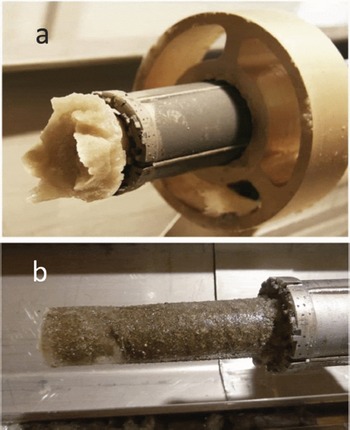
Fig. 8. Rock drill with refrozen water. (a) Refrozen water adheres to the drill head and refreezes as the drill is hoisted through a column of liquid water in the borehole. (b) Refrozen water as part of a core from the borehole that had refilled with subglacial water and refroze in 2011, and was drilled again in 2012.
Fortunately, upon its set-up the orbital motor pump could be configured to reverse the flow direction. We changed the fluid flow direction to forward flow mode, and stable drilling with the rock drill was found to be possible when pumping liquid from inside-out through the core tube. In this mode, cuttings were flushed from the drill head area from inside the core tube and transported by the drill liquid in the space between the outside of the drill tube and the borehole wall, before being filtered at the pump and recirculated back inside the drill tube to the head. In this way, however, we were not collecting most of the cuttings and they were left downhole, except those that ended up stuck to the filter surrounding the pump section.
Continuing in this mode with the rock drill, we retrieved an additional 0.65 m of silty and sediment-rich ice. The core diameter varied between 20 and 30 mm (33 mm nominal), pointing to a wobbling head and possibly drilling by partial melting of the ice. Penetration was slower in sections with more ice, and faster when more coarse material was present. This could be monitored by following the motor current needed to turn the drill, with higher and steady motor currents (>10A) when rocks were engaged. With the last attempts at the close of the 2011 campaign, it was believed that bedrock had in fact been reached because during the final runs drilling current was high and stable throughout the run, which we interpreted as characteristic of rock penetration. The screen mounted around the pump was clogged with a thick layer of very fine silt, which also indicated that we were cutting rock. However, after ∼60 cm of penetration it had not been possible to bring any core material to the surface at that time, as three attempts to catch the ‘core’ failed. The 1.39 m of core retrieved plus ∼0.6m of further penetration below the 2010 borehole in 2011 fit our assumption that we had on the order of 2 m remaining to reach the bedrock interface, so we left believing that bedrock had been reached, although not brought to the surface.
Starting again in 2012 there was constant drama in the control room as we anticipated reaching our goal, and there was surprise that turned to resignation when we continued for >7 m without reaching the bedrock interface. We started the campaign with a single run with the HT drill head with the welded carbide-plate reinforced cutters. The welded tips snapped off immediately, leaving only destroyed and unusable cutter bodies to add to the steel carnage. At this point, we concluded that the obstruction could not be penetrated with any type of cutters we had available to mount on the HT drill head, so we switched immediately to the adapted rock drill and performed 18 runs during which 7.1 m was drilled below the 2011 logging depth of 2538.1 m. The first several runs re-drilled the 51 mm diameter portion of the 2011 borehole, which had filled with refrozen meltwater, yielding frozen water cores (Fig. 8b), but also provided sediment-rich ice chips that could be collected as sample. The characteristic high and stable motor current of the final runs in 2011 was not immediately present in the re-drilling depths, but did occur several times at greater depths and was always associated with the presence of rocks in the mixed ice/rock cores collected (Fig. 9).
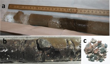
Fig. 9. Cores from the rock drill with (a) banded glacial ice and sediments and (b) an ice/rock mix, including pebble-sized stones, and (c) an assortment of stones from the rock cores.
As in 2011, the rock drill very slowly penetrated the rock/ice mixture and captured up to 70 cm of material per attempt. The cores brought to the surface were a variety of banded clear glacial ice with sediment layers and rocks (Fig. 9a). As we got deeper, more pebbles and larger rock fragments were collected within the small-diameter cores (Fig. 9b), with many different size fractions that could be sorted (Fig. 9c), though still with inclusions of clear glacial or accreted ice in each core. Preliminary assessment suggests the rocks and rock fragments were granite type with quartz minerals, along with silt, clay and fine-grain sand sediments. The exact mineralogy, basal ice properties, rock and particle size and type distribution, and general geologic framework are under investigation (personal communication from J.-L. Tison and T. Goossens, 2014).
Typical run times at the bottom (excluding hoisting and lowering) were on the order of 1–3 hours depending on the material present. In extreme cases, drill rotation was allowed to continue for up to 6 hours, which was pushing the limit for the heat generated (up to 80°C) inside the drill motor section after prolonged constant operation. Much of this drill time was used in ‘reaming’ the 51 mm borehole to regain access to the bottom, squeezing the long extensions back into the narrow borehole into which subglacial water would gradually fill and refreeze. This water, presumably together with the water created by the heat during cutting, could be seen on or in the drill when it was brought to the surface (Fig. 8). Upon hoisting, core breaks were not strong (<10kN), and the cores often broke at a sediment/rock/ice interface.
During the 18th run, a large stone (∼3cm × 5 cm) was brought to the surface, wedged in the otherwise empty core barrel. Thinking that this could have been the obstruction that halted penetration with the HT drill head, the HT drill was redeployed with cutters with carbide inserts (Fig. 4), and after a single run these came up in a severely eroded state, with inserts snapped off their mount under the press of the drilling action (Fig. 3b).
Eventually, the rate at which subglacial water entered the borehole and refroze, together with our need to close the NEEM camp, became the limiting factors in attempts to reach the bedrock. After a 10day hiatus, used to obtain more 1.5 m extension rods after we had exhausted our supply in camp, the newly formed 51 mm diameter, 7.1 m deep borehole had already been closed by refrozen water. Further penetration with the adapted rock drill was not possible in the time we had left before closing the camp. We had not reached the bedrock interface, nor had we encountered pure stone in the form of a larger boulder.
In the short time remaining we decided to attack the obstruction at the bottom that had blocked further attempts to penetrate with the HT drill head. If this obstruction could be dislodged, we would then try to penetrate further with the full diameter of the HT drill before switching back to the rock drill at greater depth as required. To dislodge the stone, a concrete diamond core bit was constructed and attached to the drill motor section and the rock-drill pump via the threaded end of an extension rod (Fig. 10). The concrete diamond bit had an o.d. of 127 mm and a 4 mm cutting kerf. After one run it was clear that we had penetrated at least partially through an obstruction. Since this cutting head was meant to be a blunt tool, it had no capability to pick up any core material. Afterwards, we deployed our conical reamer in the hope that if the stone had been dislodged we could center it in the borehole and then drill around it with the HT drill. The HT drill with the standard ice-cutting drill head was deployed, but again with no success in penetrating, and more destroyed cutters.
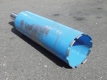
Fig. 10. Concrete diamond core bit with threaded attachment to mount to rock-drill extension rods and bayonetted connection to the pump section. This head was attached to the rock-drill extension rods, and ultimately dislodged the stone obstruction at 2538.1 m.
Nevertheless, at the end of all the drilling activities at NEEM we had the pleasure of bringing to the surface what we believe to have been this final obstruction, which was a rock ∼3–4 cm in diameter, caught within the rock-drill head. After being partially drilled through by the concrete diamond cutting head, this rock had indeed been dislodged from the borehole wall and repositioned so it apparently lay free at the bottom of the borehole, but not such that it could be avoided by the HT drill. Examination of the stone showed the signs of its having been attacked by three different tools: the HT drill with carbide insert cutters, the concrete diamond cutting head that dislodged it, and finally the rock drill into which it was jammed and in which it was brought to the surface (Fig. 11). Most encouraging for future development, perhaps, was that the HT drill with carbide inserts mounted as step cutters or as tips appears to have been mildly effective at working itself through this stone. Under different circumstances this cutter design may be effective for drilling dirty ice, particularly ice with a high concentration of small rock fragments. In this case, however, despite the slow penetration into rock with the inserts, which we were unaware of at the time, the stainless-steel cutter body holding the inserts was severely damaged, limiting their use if we were to attack the stone with a large quantity of replaceable inserts.
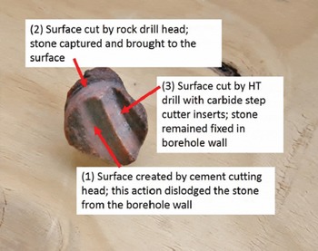
Fig. 11. The cm rock fragment which apparently stopped penetration using the HT drill was eventually dislodged from the borehole wall by mounting the concrete diamond core bit to the rock drill (surface 1). The stone was later brought to the surface when it was jammed within the rock-drill head after being partially drilled through and repositioned so it lay free at the bottom of the borehole (surface 2). Examination of the stone at the surface indicates that attempts to drill through the stone using the HT drill with carbide step cutter inserts had in fact been effective. These cutters had been slowly penetrating the stone before their eventual destruction under this action (surface 3).
Final Comments
Although the ice/bedrock interface was not reached at NEEM, an additional >7m of silty ice, rocks and other coarse materials were collected below the original obstruction that terminated normal drilling operations at 2537.36 m and again at 2538.1 m in 2011, with a combination of reinforced ‘ice’-drilling cutters and the adapted rock drill. In the end, we still did not know how far we were from the bedrock interface. Nevertheless, the rock-drill head proved quite effective at penetrating the rock/ice mixture. The smaller diameter of the rock-drill head allowed us to bypass obstacles in the borehole that stopped penetration with the HT drill head, and continue deeper. To deal with meltwater in the subglacial environment, it seems feasible that injecting ethanol around the drill head could make the tool even more effective in warm-ice environments by avoiding refreezing meltwater (e.g. Reference JohnsenJohnsen and others, 2007). Alternatively, creating an over-pressure by increasing the drill fluid height could prevent meltwater from seeping into the borehole. Such a scenario will be unacceptable, however, if maintaining a ‘clean’ subglacial environment is a priority. But, with the rock drill now adapted to be used with the NEEM (or any HT-type) drill, it will be a tool we keep ‘on the shelf’ for future drillings that approach the bedrock foundation of ice sheets or glaciers. With the combined capabilities of the adapted rock drill, effective reinforced cutters of the ice drill, and blunt tools when necessary, it seems plausible that the system used at NEEM could succeed in collecting not only debris-rich basal ice, but also the bedrock itself. Tensile strength of granite for a rod of comparable size to the rock-drill core diameter is on the order of 10MPa, which is well within the limits of the force available with the winch and cable used at NEEM.
Acknowledgements
We thank the many logistical hands at NEEM, in Copenhagen and at Ice Coring and Drilling Services, Madison, WI, that supported us during our long shifts, sometimes in a darkened drill trench, in the final seasons at NEEM collecting basal ice and debris. NEEM is directed and organized by the Center for Ice and Climate at the Niels Bohr Institute, and the US National Science Foundation (NSF) Office of Polar Programs. It is supported by funding agencies and institutions in Belgium (FNRS-CFB and FWO), Canada (NRCan/GSC), China (CAS), Denmark (FIST), France (IPEV, CNRS/INSU, CEA and ANR), Germany (AWI), Iceland (RannIs), Japan (NIPR), Korea (KOPRI), The Netherlands (NWO/ALW), Sweden (VR), Switzerland (SNF), United Kingdom (NERC) and the USA (US NSF, Office of Polar Programs).


