


Introduction
Exploration of the interior of the Antarctic ice sheet and its bed has proceeded slowly but steadily over several decades. The significance of emerging scientific questions combined with transformative technological innovations motivates a rapid alternative to traditional methods of ice coring and rock drilling (Talalay, Reference Talalay2016). These new technologies include high-resolution optical borehole logging (Bay and others, Reference Bay, Price, Clow and Gow2001), which has lessened the need for traditional continuous ice cores and compels the need for multiple deep boreholes. Furthermore, the search for 1.5 million year-old ice requires fast, low-cost reconnaissance drilling without need for long ice cores (Fischer and others, Reference Fischer2013; Alemany and others, Reference Alemany2014; Schwander and others, Reference Schwander, Marending, Stocker and Fischer2014; Van Liefferinge and others, Reference Van Liefferinge2018). Pressing questions about future sea-level rise have also established an urgent need for in situ borehole observations in Antarctica (NASEM, 2015), including ice deformation, geothermal heat flow and basal material properties. Growing concern relates to stability of the East Antarctic ice sheet and its potential contribution to sea-level rise, which are highly uncertain and often overlooked (Fogwill and others, Reference Fogwill, Golledge, Millman and Turney2016). Furthermore, most of the Antarctic geological map remains blank due to ice cover, hampering understanding of how the Antarctic continent was assembled (Boger, Reference Boger2011). This is best addressed by a survey program of short rock cores taken quickly from multiple sites beneath the ice in order to ground-truth interpretations made from geophysical remote-sensing data. From this background, the concept was born of a ‘rapid-access ice drill’ (RAID) that quickly explores the ice-sheet interior without committing resources to long ice cores, but rather by taking larger numbers of short cores of materials with high scientific value.
To address these aspirational scientific goals, the RAID (http://www.rapidaccessicedrill.org) was designed to quickly drill through deep ice (penetration up to 3000 m depth in 48 h) on the ice sheets of Antarctica, followed by coring of ice, penetration of the ice-sheet–bed interface, and coring of subglacial bedrock below (Goodge and Severinghaus, Reference Goodge and Severinghaus2016). Rapid penetration of the Antarctic ice sheets will allow scientists to take multiple short cores in deep ice, from the glacial bed, and from bedrock below, and to create long-term borehole observatories. As a complete system, RAID is unlike other ice-penetrating tools, although a similar drilling system optimized for transport by a light aircraft utilizes the RAID concept (Kuhl and others, Reference Kuhl2020). It is a sled-mounted mobile drilling system capable of making multiple long (up to 3300 m), narrow (8.9 cm, or 3.5 in diameter) boreholes in a single-field season on the ice sheets of Antarctica. RAID is based on a mineral exploration-type rotary rock-coring system using threaded drill pipe to cut through ice, with circulation of a non-freezing, environmentally safe fluid for removal of ice cuttings and to provide pressure compensation. Near the bottom of the ice sheet, a wireline latching assembly enables the taking of rapid short cores of ice, the glacial bed and bedrock below. Once complete, boreholes will be kept open with fluid for a nominal period of 5 years, making them available for future down-hole measurements of temperature gradient, heat flow, ice chronology, ice deformation, seismic experiments and astrophysics.
The RAID drilling system was designed, fabricated and tested in Utah between 2013 and 2015, and delivered to the US Antarctic Program (USAP) in November 2015. After shipment to Antarctica the project conducted two sets of Antarctic Field Trials (AFT) in 2016–17 and 2017–18 (AFT1 and AFT2, respectively) in order to test all of the components, validate performance specifications and demonstrate full capability of the drilling system in the Antarctic environment. Although some operational goals were achieved, these technology development tests fell short of reaching the principal goals of rapid deep-ice penetration and coring of deep ice and subglacial bedrock. Since then, significant inspections, modifications and testing were performed during the 2018–19 austral field season in McMurdo and the system was readied for further testing. A third set of full-scale AFT3 was conducted during the 2019–20 austral season at Minna Bluff in the McMurdo Station operating area and is the focus of this contribution.
The over-arching goal for AFT3 was to successfully demonstrate the functionality of RAID by operating at its design capability in the Antarctic environment. In detail, the goals for AFT3 were essentially the same as specified for earlier field trials, which were undertaken with an experimental approach as part of the real-world development process. Our intent with AFT3 was to successfully complete a ‘top-to-bottom’ operational sequence for a set of three holes by augering through firn, installing a borehole packer and achieving a seal in non-porous ice, establishing fluid circulation, quickly drilling a borehole in ice, acquiring a short ice core at depth, penetrating the glacial bed and recovering subglacial basal material, acquiring a subglacial rock core, logging the borehole on wireline, conducting a test of hydraulic fracture (or hydrofracture) potential by over-pressuring the borehole fluid and operating in an environmentally benign way. All of these major objectives were achieved during the 2019–20 field trials.
This paper summarizes the successful drilling activities of the RAID system at Minna Bluff during the 2019–20 austral summer season, providing a synopsis of operational successes and drilling outcomes.
Minna Bluff drill site
A small piedmont glacier ~90 km south of McMurdo on the south side of Minna Bluff provided the best location for full-scale field trials of the RAID drilling system (Fig. 1). At Minna Bluff, grounded ice has a known thickness of ⩾600 m (as determined by ice-penetrating radar), and it is easily accessible by traversing across the Ross Ice Shelf along the established South Pole traverse (SPoT) route. The transition between the ice shelf and the piedmont glacier is smooth and relatively crevasse-free, and the route rises gently above the ice shelf at the small ice plateau. Depending on route, the over-snow traverse distance is <200 km and can be completed in 2–3 d from McMurdo Station, barring hazardous or severe weather conditions. Proximity to McMurdo provides easy access by helicopter and small fixed-wing aircraft, quick response to medical emergencies and support by machine shops, heavy vehicle shops and general supply in the USAP system. Disadvantages of the Minna Bluff site are potentially high geothermal heat flow, high snow accumulation, stressed ice due to rapid ice flow and relatively warm summer temperatures, all presenting significant challenges as discussed further below.

Fig. 1. Satellite imagery of Minna Bluff test site area. (a) General location relative to Ross Island, Mount Discovery and McMurdo Station. (b) Detailed image showing location of AFT3 test site on a small piedmont glacier south of Minna Bluff. Black line shows location of airborne radar line shown in Fig. 2.

Fig. 2. Airborne ice-penetrating radar profile crossing Black Island and Minna Bluff (see Fig. 1), showing location of AFT3 drill site over local basement high confirmed to a depth of 681 m by drilling. Radar image was collected as part of the NSF GIMBLE and NASA SIMPLE projects (Grima and others, Reference Grima2019; image courtesy of D. Young).
The traverse route from McMurdo and the drilling test sites were surveyed by ground-penetrating radar ahead of time in order to provide crevasse detection and ensure safe field operations. The single most significant hazard on traverse is a wide glacial shear zone separating the northward flowing Ross Ice Shelf from ice contiguous with McMurdo Sound (Fig. 1a).
Figure 1a shows the regional setting of McMurdo Sound, the Ross Ice Shelf and Minna Bluff. This area is primarily underlain by rocks of the McMurdo Volcanic Group, chiefly alkaline basalts exemplified by the eruptive units on Ross Island, Mount Erebus and Mount Discovery (see summary by Goodge, Reference Goodge2020). Minna Bluff is a narrow, 45 km long ridge extending southeast from Mount Discovery, a Miocene alkaline stratovolcano. The principal rock types are basanite and phonolite containing large (up to 5 cm long) kaersutite and feldspar megacrysts, abundant comagmatic inclusions (kaersutite-rich) and rare mantle xenoliths. Since the late Miocene, Minna Bluff has been a terminal pinning point for the Ross Ice Shelf and is a local topographic barrier helping to block the Ross Ice Shelf from flowing into McMurdo Sound. Eruptions of alkaline basalt occurred between ~8 and 12 Ma (Wilch and others, Reference Wilch2011), during which time lavas partly interacted with ephemeral glacial ice. Minna Bluff is surrounded by thick, relatively stable ice of the Ross Ice Shelf, which extends past White Island to McMurdo Station (Fig. 1b).
The RAID project conducted field trials at similar locations near Minna Bluff in 2016–17 (AFT1), 2017–18 (AFT2) and 2019–20 (AFT3). Locations of the three AFT3 drilling sites were near 78°37.61′ S and 166°40.87′ E (Fig. 1b; Table 1), and the site elevations were ~250 m above sea level. An airborne ice-penetrating radar line (line Y39a; Figs 1b and 2; Grima and others, Reference Grima2019) transects the eastern of the two small ice plateaus next to Minna Bluff and the eastern flank of Black Island. On its southern end, this radargram shows the transition between thick ice overlying water in the Ross Sea and bedrock of Minna Bluff. A grounding line is clearly visible at ~75 km along the profile (at the surface break in slope). The very intense, flat reflector at ~−400 m depth is the base of floating ice over seawater, and it shows strong multiples (reflected radar waves) below. The rougher reflector toward Minna Bluff is the grounded ice interface. Internal reflectors within grounded ice show a continuous record of ice accumulation banked against bedrock, although image resolution is not sufficient to evaluate possible ice layer disturbance during fast flow over the glacier base. A test site for AFT3 drilling trials in 2019–20 was selected above a slight bedrock high visible in the radargram, which was thought to reduce the risk of drilling into unconsolidated sediments.
Table 1. Minna Bluff borehole summary

Given that the region of Ross Island and Mount Discovery constitutes a young volcanic province, it is worth considering possible effects of high heat flow on ice stability. Measured heat flow values in the McMurdo area range from 66 and 79 mW m−2 in igneous rocks of the Dry Valleys (Decker and Bücher, Reference Decker, Bücher and Craddock1982) to 115 mW m−2 in sediments north of White Island (Morin and others, Reference Morin2010). A crucial requirement for environmental stewardship is to avoid contaminating a subglacial water system, so RAID must not penetrate a wet bed. To address the thermal state of grounded ice in the vicinity of McMurdo prior to site occupation, we modeled the thermal profile of 600 m thick ice using the estimated parameters of average annual surface temperature, snow accumulation rates and an intermediate geothermal heat flux of 80 mW m−2 (Fig. 3). At 680 m depth, grounded ice in this area is expected to have a basal temperature of ~−10°C. These results indicated that drilling in this area would not intersect subglacial hydrology.
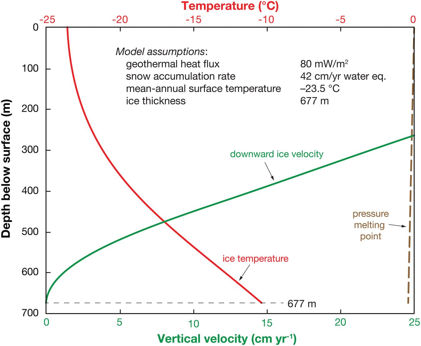
Fig. 3. Modeled temperature profile at Minna Bluff. Temperatures at the base of the glacier are expected to be a little below −10°C (red line) and well below the pressure-melting point of −0.4°C (brown dashed line) assuming a regional mean geothermal heat flux of 80 mW m−2, snow accumulation rate of 42 cm a−1 (w.e.) and mean annual surface temperature of −23.5°C. Ice thickness is 677 m based on borehole depth to glacial bed. Also shown is downward ice velocity (green line).
RAID configuration and operation
The RAID system consists of five ski-mounted modules – drill, rod, fluid recirculation, shop and power (see Goodge and Severinghaus, Reference Goodge and Severinghaus2016). The first two of these were built in custom-designed and fabricated cold-tolerant steel frames and the latter three modules were fitted inside 40 ft standard ISO shipping containers. Drilling is done with a modified Boart Longyear LF-230 rotary exploration-type drill using custom augers for making boreholes in firn, and with NQ drill rods equipped with custom ice-cutting and coring tools for making boreholes in ice and rock. The system is driven by an electric motor fed by twin (redundant) diesel Caterpillar C-18 500 kW generators, operating alternately. The modules are mounted on ISO-3 ski systems with a walking-beam design for flexibility during movement over uneven surfaces without stressing the module structures. During field drilling operations, the RAID modules are aligned in two rows as shown in Fig. 4, in close enough proximity to allow power and hose connections. The modules were moved to Minna Bluff and between drill sites using Caterpillar Challenger and Case Quad-Trac tractors. Once in place, a fabric canopy is erected over the work deck connecting the drill and rod modules, supported by the drill mast. Liquid consumables required for operation are diesel fuel, glycol used in heat exchange and ESTISOL™ 140 drilling fluid.

Fig. 4. RAID drilling system in field deployment configuration. (a) Aerial view of RAID drilling modules in position at Minna Bluff test site. Modules: D, drill; F, fluid recirculation; P, power generation; R, rod storage; S, shop and tools. (b) View of the drilling modules from the ground.
During drilling, the system is operated by a lead driller on the LF-230, with assistance from 1 to 2 drill hands to handle auger and pipe assembly and disassembly, and one person to oversee the automated fluid recirculation system (FRS). Ideally, regular operation of the RAID system can be managed by a 3–4 person crew.
The FRS is a custom-designed module for supplying cold drilling fluid to the borehole and separating drilling fluid from ice cuttings as they are evacuated from the borehole. It is the heart of the RAID system. A schematic layout of the FRS is shown in Fig. 6 by Goodge and Severinghaus (Reference Goodge and Severinghaus2016), and photographs of the main components inside the FRS are shown here in Fig. 5. As described by Goodge and Severinghaus (Reference Goodge and Severinghaus2016), the FRS is divided into a cold side kept at ambient temperature and a warm side heated sufficiently to maintain liquid water above freezing. Supply of fresh, cold ESTISOL™ 140 is provided by tanks in the cold room prior to injection into the borehole (Fig. 5a). Drilling fluid returned from the borehole with suspended ice cuttings enters the cold room and undergoes a first-stage mechanical separation from cuttings by means of shaker screens (Fig. 5b). The remaining cuttings wetted with drilling fluid are passed through a room divider and dumped into a melting tank to create a two-phase mixture of water and ESTISOL™ 140 (Fig. 5c), and then this mixture is pumped into a second-stage coalescing tank (Fig. 5d) where lighter ESTISOL™ 140 is floated above water, skimmed by a tubular weir, and the two liquids are then drained into separate single-phase tanks. Processed fluid is then filtered before returning to the cold-room supply tanks where it is pre-chilled prior to pumping back into the borehole. All of the tanks, pumps and filters are monitored by a programmable logic control system in order to maintain tank levels, exchange rates and temperature.

Fig. 5. Photographs showing key components of the FRS. (a) Cold side of the FRS module, showing supply tanks (blue) and primary borehole staging tank (silver). (b) Vibrating shaker consisting of two overlying screens operated by means of an eccentric belt drive. (c) Melting tank inside the warm room, containing a submerged glycol-loop manifold connected to a diesel boiler. (d) Coalescing tank containing baffles and a weir that drains ESTISOL™ 140 floating on water.

Fig. 6. Photographs showing key drilling components of RAID system. (a) Auger flights being raised into drilling position. (b) Close-up of the auger cutting head, consisting of a pair of hardened steel cutters. (c) Inflatable casing packer, shown in position below the drill head and connected by subs (blue) to HWT casing at top and bottom. Rubber element (black) is pressurized from a fitting entering at the top of the upper sub. (d) ‘Water’ swivel suspended on the main line by a shackle and connected to NRQ drill rods passing through the drill head. In reverse circulation, drilling fluid and suspended cuttings move up the drill rods and exit from the top of the swivel into a hose connected to the FRS module. This is one design of swivels tested. (e) Ice-cutting bit made from hardened tool steel and consisting of an outer assembly to which four cutting blades are attached, and an inner assembly holding two cutting blades. (f) Coring bits, including, from left to right, bit with A2 tool steel cutters, PCD wafer bit and a conventional mineral industry-type impregnated diamond bit.
ESTISOL™ 140 was selected as the optimal drilling fluid for the RAID system because of its ideal density, hydrophobic property, low viscosity at cold temperatures and colorless, translucent property suitable for borehole optical logging. ESTISOL™ 140 is a synthetic, ester-based solvent with some known negative material effects and physical irritation. As noted by Sheldon and others (Reference Sheldon, Popp, Hansen and Steffensen2014), ESTISOL™ 140 is absorbed by, expands and degrades some common materials used in seals, pipe and tool housings (e.g. polyvinyl chloride, nitrile rubber, and many common plastics), so appropriate alternatives must be used. ESTISOL™ 140 has a sweet odor that some people find unappealing, but it evaporates quickly after absorption in clothing and absorbent materials if left in a warm, dry setting. ESTISOL™ 140 also can be a skin irritant, particularly causing severe drying due to removal of natural oils. Our drillers generally find the workability of ESTISOL™ 140 to be superior to other drilling and machine fluids, including diesel fuel, and with proper protective clothing and ventilation it is easy to work with. Despite its low vapor pressure compared to other drilling fluids (Sheldon and others, Reference Sheldon, Popp, Hansen and Steffensen2014), some physical side effects can be anticipated due to evaporation from clothing in heated and poorly ventilated spaces on the Polar Plateau (e.g. Johnson and others, Reference Johnson2020).
RAID's 8.9 cm (3.5 in) ice boreholes require 0.62 m3 (164 gal) of drilling fluid for every 100 m of borehole length, plus provision for filling supply tanks in the FRS, making hose connections, and possible losses due to hydrofracture. After scientific drilling, all RAID boreholes will be left filled with ESTISOL™ 140 in order to maintain open boreholes for 5 years for follow-up wireline logging, so an adequate supply of drilling fluid must be provided at the beginning of a drilling season.
In this paper, dimensions, rates and other values are provided in SI units, and US customary measures are indicated when applicable to US-manufactured equipment.
Earlier field trials and challenges to drilling
Important lessons were learned in the first three tests of the RAID system. These three tests were: (1) a North American Test (done in Utah in a column of artificial ice; Nielson and others, Reference Nielson, Delahunty, Goodge and Severinghaus2017), (2) Antarctic Field Trial 1 (known as AFT1) at Minna Bluff in the 2016–17 season and (3) Antarctic Field Trial 2 (AFT2) at Minna Bluff in the 2017–18 season.
The North American Test demonstrated the viability of the basic concept of fluid-assisted ice chip removal from the borehole and verified that the novel FRS could successfully remove ice chips from the ESTISOL™ 140 drilling fluid in order to re-inject clean fluid down the borehole. The design rate of ice penetration of 3 m min−1 was achieved, which is integral to the concept of rapid drilling.
In AFT1, we learned to avoid getting augers stuck in the firn by decreasing the rotation rate so as not to induce melting and refreezing of cuttings, and to bring extra auger flights to the field in the anticipation of encountering firn layer thickness greater than expected. Progress was also limited by not fully anticipating equipment needs. On the positive side, AFT1 demonstrated the soundness of mounting modules on skis, capability of traverse vehicles, functioning of the power module temperature control system and rig set-up and take-down. AFT1 also showed that it is possible to auger quickly through firn (3 h) to 79 m depth, with no issues of excessive torque, which had been a concern.
Lessons from AFT2 included recognition that improper auger cutting head geometry (in particular, misalignment or ‘clocking’ of the cutters with respect to the openings onto the auger flights) causes clogging of the bit with ice and contributes to the risk of getting the auger string stuck. A crucial lesson was that hydraulic fracturing of the ice due to fluid overpressure is an inherent risk that must be carefully managed going forward. Here, we use overpressure to mean the excess borehole fluid pressure required to induce fracture in ice, which we define simply as the total fluid pressure minus the ice pressure or, more explicitly, the surface fluid pressure measured at the pump plus the fluid hydrostatic pressure in the borehole column minus the ice hydrostatic (or overburden) pressure. Overpressure in this context is the fluid pressure required to hydraulically fracture ice at depth in a borehole (see Chen and others, Reference Chen2019). At AFT2, the ice hydrofractured at an overpressure of only 0.7 MPa, or 105 psig, even though the drill design calls for overpressures as high as 1 MPa, or 150 psig, in order to circulate the fluid during deep drilling. It was also demonstrated that too close a proximity of boreholes in AFT2 (<100 m separation) might have contributed to hydrofracture by weakening the ice, particularly under the warm conditions at Minna Bluff.
As with earlier field trials, AFT3 was an exploratory, experimental step in the RAID development program. Probing the unknown carries with it inherent challenges, including: (1) a new drilling team that is highly skilled at rock drilling and operation of the LF-230 drilling rig, but lacking experience in drilling firn or ice; (2) warm surface temperatures that caused melting and refreezing, and required careful, continuous temperature control and fluid management to avoid clogging of hoses and pipes; (3) high snow accumulation rate and thick firn; (4) dynamic glacial ice under stressed conditions with lowered strength and greater susceptibility to hydrofracture; (5) risk of ice fracture upon hitting hard materials such as rocks above the bed, even with standard operating fluid pressure of 0.5–1.0 MPa; (6) imprecise knowledge of depth to bedrock, requiring careful monitoring for a switch from ice-cutting to rock-coring; (7) unknown bed materials, properties and width of the ice–rock transition; (8) inoperable or inadequate air conditioning units used to chill the cold room of the fluid recirculation module (these chiller units are only needed at the low elevations of Minna Bluff and not part of the permanent RAID equipment for Plateau operations); (9) learning through experimentation with new equipment (e.g. use of a newly designed pressure relief valve (PRV) applied to multiphase fluids consisting of ESTISOL™ 140, ice chips and, potentially, water contamination); (10) limited supply of drilling fluid, in part due to some fluid losses in firn and hydrofractured ice and (11) episodic lack of a sufficient volume of chilled drilling fluid needed to maintain fast ice drilling for sustained periods of time despite pre-chilling of fluid with a refrigeration unit and burying fluid supply totes below the surface to shield them from solar heating.
Some of these challenges were known or expected from previous field trials (1, 2, 3, 4, 6, 7, 8, 9) whereas some were not expected and first encountered during drilling (5, 8, 10, 11). Despite these factors, the principal goals for the field trials were accomplished due to ingenuity on the part of the drill team and a careful, deliberate approach to all operations. Many of these challenges will be mitigated when drilling on the Polar Plateau, where surface temperatures are much colder than at Minna Bluff. For example, supplying pre-chilled drilling fluid will not be a problem on the Polar Plateau due to cold ambient temperatures that will likewise keep all of the fluid cold.
Drilling components
In order to achieve rapid, deep ice cutting using RAID's rotary drilling system, our conceptual approach is to auger wide holes through firn to reach impermeable ice, set a pressure seal adequate for borehole fluid circulation using an inflatable casing packer, switch to smaller bore ice drilling tools using reverse fluid circulation to evacuate ice cuttings from the borehole and finally perform wireline coring with a latching bottom-hole assembly during normal fluid circulation. To the extent possible, RAID uses off-the-shelf, commercially available drilling components, but some equipment was custom designed specifically for this system. Key drilling components used in the AFTs are described below and illustrated in Figs 6 and 7.

Fig. 7. Chip bailer used to clear cuttings from the auger borehole. (a) CAD model of the IDP 4-in Drill fitted with the chip bailer auger and head. The outer tube of the drill barrel is shown transparent in order to show the chip bailer auger assembly. (b) The IDP 4-in drill winch (W), tower (T) and control box (C) set up on the RAID work deck. (c) Chip bailer, in process of unloading cuttings, consisting of a steel barrel housing internal screw flights.
Augers
RAID uses modified soil augers composed of cold-drawn steel tubing, hex shanks with box-and-pin type fittings and helical flights with an outer diameter of 14 cm (5.5 in) and spacing (pitch) of 12.7 cm (5 in). Augers were manufactured in sections of 1.52 m (5 ft) lengths. During firn augering, the auger flights are attached sequentially to the drill rig with a custom-made sub (Fig. 6a). Despite being made new for use in the dry Antarctic environment, the steel augers developed rust on the surfaces of the auger flights, which we suspect hindered chip transport needed for clearing holes. Removal of rust from the upper surface of the auger flights by wire brush significantly improved chip transport. Also, we discovered in the field that ~10% of the augers were fabricated incorrectly and were too wide, approaching 15.2 cm (6 in) diameter. These ‘wide’ augers caused excess frictional heating of the borehole wall and sintering of the ice chips, resulting in the auger string getting stuck in the ice in one instance. Augers were ultimately released by slowly deploying 19 L (5 gal) of hot glycol down the auger shafts over a period of 72 h.
Auger cutting head
Custom cutting heads were designed for penetration with the augers into firn and ice. A refined design consists of a steel ring and circular base plate to which a pair of angled shoe-type cutters is attached (Fig. 6b). During the augering process, cuttings are fed efficiently through wide openings onto the auger flights if ‘clocked’ properly as shown. The current design has an outer diameter of 15 cm (5.9 in).
Chip bailer
In cooperation with the US Ice Drilling Program, we developed a chip ‘bailer’ to clear the bottom of the auger hole of cuttings, and to help smooth the wall for better seal with a packer. The auguring process has been found to leave 5–20% of the borehole depth filled with cuttings. These cuttings must be removed so the packer and casing can be set at the bottom of a clean borehole. If the cuttings are not removed, and the packer is set above them, the cuttings are flushed out in an uncontrolled manner by the circulating drilling fluid while drilling, which causes surges and pressure spikes and can increase the risk of hydrofracturing of the ice. The new IDP chip bailer was designed to efficiently remove these cuttings and is operated by the IDP 4-in Drill.
The chip bailer is an ~2 m long auger section with a full face-cutting bit that fits inside the outer coring tube, in place of the core barrel used with the IDP 4-in Drill (Fig. 7a). The flights on the lower portion of the auger have a close fit with the outer tube for efficient chip transport, whereas the flights on the upper portion have a reduced diameter to prevent the cuttings from initially transporting all the way to the top of the barrel and packing off before the lower portion fills. Once the augers are run to depth and removed, the IDP 4-in drill is moved into position on the RAID work deck (Fig. 7b). This setup could be better optimized for future deployment with the RAID system, but it served well to prove the bailing concept during the RAID AFT3 season.
Rotating at ~100 rpm, the chip bailer was lowered at a feed rate of 2.6 m min−1 into the cuttings. Approximately 90–100 cm of cuttings were collected per run; however, we feel this could be improved with further modifications to the auger section. The bailer was then winched back to the surface and rotated in reverse to unload the cuttings (Fig. 7c) before being sent back down the borehole for another run. Bailing runs were completed in as little as 6 min at 80 m depth. Once all of the cuttings were bailed from the borehole, the bailer was replaced with the 4 in drill core barrel with coring head. The borehole was then deepened a minimum of 3 m, recovering 1 m long ice cores per drill run, to provide a smooth, crack-free ice wall for the packer to seat against. Precise density measurements were made on the recovered ice cores to ensure it was a minimum of 860 kg m−3, which has been determined to be the minimum density required for proper sealing of the packer. If the measured density was too low, the borehole was deepened with the core drill until the target density was reached. The borehole was then ready for installation of the casing and packer.
Casing
Casing is used inside the firn borehole to connect the diverter to the packer. It is conventional threaded steel casing in standard HWT size with an outer diameter of 11.4 cm (4.5 in).
Packer
RAID uses an inflatable casing packer consisting of upper and lower threaded subs compatible with HWT casing, and a 1 m long cylindrical composite-rubber mid-body element equipped with a fitting for connection to a narrow gas line for pressurization (Fig. 6c).
Drill rods
Conventional Boart Longyear NRQ-size (outer diameter: 6.99 cm or 2.75 in) threaded steel drill rods are used for ice drilling. The rods have a thin-wall mid-body (V-wall design) to reduce overall weight on the drill string. Rods are manufactured in 3.05 m (10 ft) lengths and made up in the field to ~9 m (30 ft) sections.
Swivel
Off-the-shelf, industrial ‘water’ swivels are used at the top of the drill string to circulate drilling fluid back to the FRS module. Swivels typically have dual body parts that are allowed to rotate by means of seals and bearings, in which the upper part remains attached to the drill main line and the lower part rotates with the drill string (Fig. 6d). We used several different swivel designs and modified them to reduce the curvature of the hose connections and to make use of an in-line ball valve during make-up of drill rods.
Pressure relief valve
Off-the-shelf, adjustable, spring-type PRVs along with a bleed-off reservoir were used in the fluid system in order to prevent pressure spikes in the drilling fluid (most commonly due to clogging with ice cuttings) from causing a hydrofracture in ice. A PRV is inserted in the fluid line downstream from the Bean pump and prior to connection with the borehole diverter. Pressures were typically set between 0.5 and 1.0 MPa (70 and 150 psi). The PRVs worked well to prevent pressure spikes, but in practice the adjustable range was too coarse.
Ice-cutting bits
Ice-cutting bits were custom designed for RAID. They consist of an outer cutting bit threaded onto the drill string and an inner latching bit that can be removed on wireline for deployment of the coring assembly (Fig. 6e). The outer bit has a nominal outer diameter of 8.89 cm (3.5 in) and a 5.66 cm (2.23 in) opening to accommodate either the inner face-centered bit or the coring assembly. An initial design utilized tungsten carbide cutters at a moderate rake angle on the outer bit and near-vertical twin cutters on the inner bit. This early bit design was effective against ice but was subsequently refined to use cutters made of hardened tool steel with a more aggressive cutting geometry. As shown in Figure 6e, the new geometry and arrangement of cutters is optimized for efficient cutting and transport of cuttings upward into the drill rods, producing ice chips with a nominal size of 2 mm.
Coring assembly
RAID uses a proprietary, custom-designed bottom-hole coring assembly consisting, from top to bottom, of a latch-head subassembly connected to wireline, a 3 m long B-size coring rod, a landing subassembly, coring rods and coring bit. This assembly fits within the NQ drill rods and latches to the outer ice-cutting bit, thus allowing it to rotate with the drill string by turning at the drill head.
Coring bits
Different styles of the coring bit were developed for use in ice, sediment and rock. These include bits with steel cutters, polycrystalline diamond (PCD) bits and conventional mineral industry-type impregnated diamond bits (Fig. 6f). Coring bits are threaded onto 3 m long B-size core barrels with an outer diameter of 5.56 cm (2.19 in), enabling coring runs in 3 m increments. All of the bits are of thin kerf design with a nominal outer diameter of 5.56 cm (2.19 in) yielding a core diameter of 3.84 cm (1.51 in).
Field sites and borehole completions
RAID was deployed between 7 November 2019 and 10 February 2020, and the field site at Minna Bluff (Figs 1 and 2) was occupied by the RAID team between 2 December 2019 and 31 January 2020. We completed four boreholes at three sites, as listed in Table 1.
Augering, drilling and coring parameters
Augering was typically completed by rotating at 100 rpm at penetration rates of 1.2–1.5 m min−1 (4–5 ft min−1), progressively slowing with depth in order to accommodate the increasing chip volume flux as the firn density increases. Chips were unloaded at a speed of 300 rpm.
Borehole ice drilling was done in reverse fluid circulation. Drilling parameters were varied according to conditions and as informed by experimentation and troubleshooting. Typically, however, ice drilling in holes 2 and 3 was completed in 9 m rod sections with the drill running at rotation rates of ~100–250 rpm, torques of 450–700 Nm, fluid circulation of 76–114 L min−1 (20–30 gal min−1), fluid pressure of 0.5–1.0 MPa and fluid input temperatures of −8 to −22°C. Penetration rates in ice ranged from ~0.75 to 1.2 m min−1 (2.5 to 4.0 ft min−1), but were slower at times as conditions warranted.
Rock coring was completed in normal fluid circulation, with drill speeds of 130–200 rpm, fluid circulation of 30–38 L min−1 (8–10 gal min−1) and fluid pressure of 1.4–2.1 MPa, resulting in penetration rates of 1.25–25 cm min−1 (0.5–10 in min−1).
Overview of results
A successful third round of Antarctic Field Trials (AFT3) was completed with RAID at Minna Bluff during the 2019–20 austral season. We achieved all major goals identified for AFT3, despite a number of both inherent and unexpected challenges, as outlined above. Highlights of major outcomes include the following:
(1) Fast and trouble-free augering of three firn boreholes to accommodate a packer at depths of 85–107 m, now established as a reliable method for making holes in firn. Borehole packers were set at a minimum density for non-porous ice of 860 kg m−3, as measured from short 1 m long cores (see below).
(2) Successful testing of a new borehole chip ‘bailer’, designed and built by the US Ice Drilling Program (IDP), to remove firn cuttings and ready the borehole for deployment of a packer.
(3) Demonstrated the first use of a conventional ice core drill (IDP 4-in Drill) with modified cutters to make a smooth, microcrack-free packer seal, and to recover several meter-long ice cores for density verification.
(4) Demonstrated via testing that 2.4 MPa (350 psi) is a safe and effective pressure for packer inflation with air or nitrogen gas in order to seal off the permeable firn with casing.
(5) Collection of core samples from the firn–ice transition for atmospheric H2 measurement.
(6) Rapid deep-ice drilling using a non-coring rotary ice-cutting bit with reverse fluid circulation (penetration up to 678 m, setting a new Antarctic depth record for rotary reverse-circulation drilling in ice).
(7) First successful use of a custom-built PRV to prevent accidental hydrofracture of ice by uncontrolled spikes in fluid overpressure.
(8) Measurement of temperature (−10°C) at the bottom of a borehole reaching the glacier bed, demonstrating a cold-based glacier and validating our thermal model prediction of −10.3°C.
(9) Successful penetration into a mixed zone of glacial ice, mud and glacial debris, all while maintaining fluid circulation.
(10) Cored 1 m of near-basal ice for gas, age and isotopic analysis using wireline coring inserts. Basal ice was dated at ~15 000 years using the δ18Oatm method (Severinghaus and others, Reference Severinghaus, Beaudette, Headly, Taylor and Brook2009).
(11) Penetrated the glacial–subglacial boundary by coring from ice into basal glacial till and recovering a 3 m core of bedrock tillite from just below the ice–rock transition.
(12) Obtained borehole optical logs using a newly designed ‘slim’ laser dust logger sized for RAID boreholes.
(13) Obtained borehole video logs using an optical televiewer.
(14) Developed a new method to quickly remove drilling fluid from boreholes via a fluid evacuation swab hoisted on a wireline.
(15) Achieved completion of down-rigging, packing, moving and re-rigging the RAID system between drill sites in <36 h.
(16) Achieved penetration rates of up to 1.2 m min−1 (limited by cutting bit geometry). Not accounting for time involved in making up drill pipe and other factors, this corresponds to an equivalent drilling rate of 600 m (~2000 ft) in ~8 h, or 3000 m (nearly 10 000 ft) in <48 h.
(17) Discovered that hydrofracture risk does not increase with depth, as some ice experts had predicted.
(18) Posted blogs from the field (http://www.rapidaccessicedrill.org/blog/) to provide a real-time picture of life in the field and RAID drilling progress for the general public.
The following are brief summaries of the boreholes made at three sites (Fig. 8), based on detailed daily drilling logs completed by the drilling crew, weekly summaries of activities and individual notes from the field trial operations that document detailed sequences of events, drilling parameters and drilling outcomes.
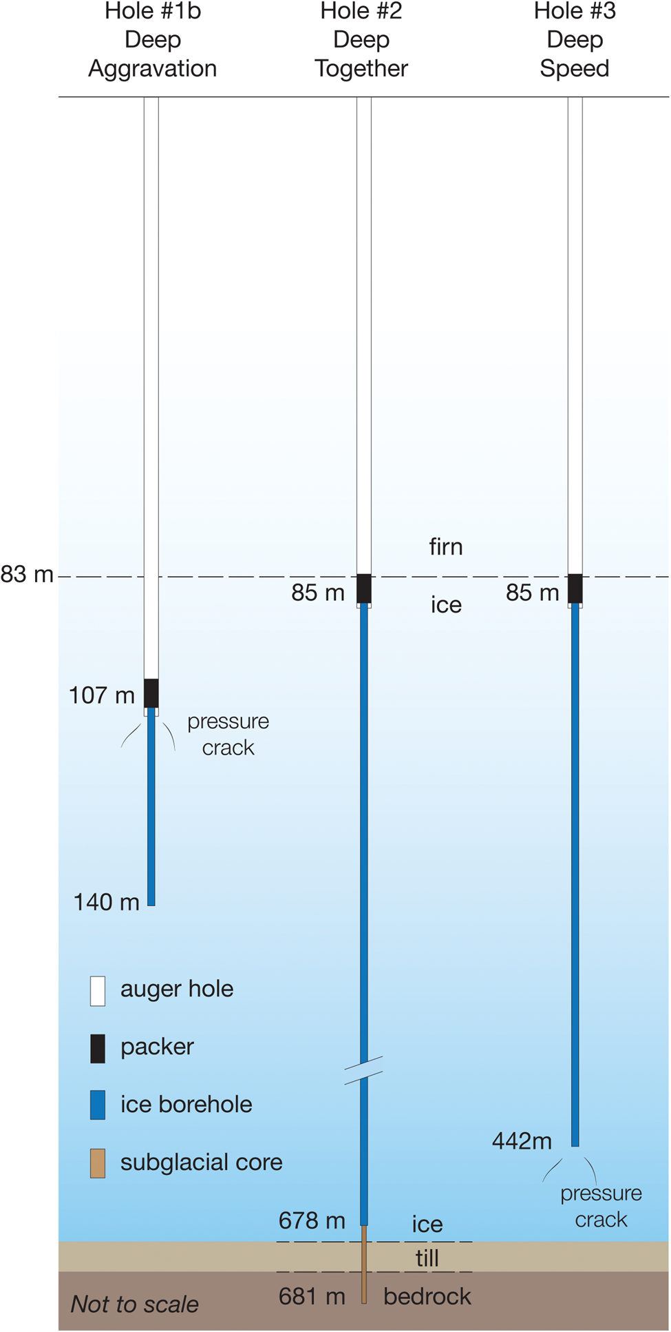
Fig. 8. RAID boreholes completed at Minna Bluff in 2019–20 and as named by the drill team. Note non-uniform depth scale and scale breaks below 83 m.
Hole 1a was started by augering to a depth of ~67 m, when the drill torque climbed as the cutting bit started packing off. At a depth of ~70 m, part of the cutting head broke off at the bottom of the hole, so a decision was made to abandon the hole and pull out the auger string. Conditions were warm enough that melting may have occurred at the cutting head, and a slow penetration rate produced cuttings that were too fine so that they caked together and were poorly transported on the auger flights.
After moving the drill and rod modules a short distance without moving the other modules, hole 1b was started. We augured to ~90 m in a short time, but the auger string became stuck when trying to pull it out with no rotation. We applied small amounts of glycol in the borehole to free the stuck augers, and after stepwise application the augers eventually came free and were removed. The borehole was further deepened and cleared of glycol by using the IDP 4-in Drill and the new chip ‘bailer’ to a depth of ~107 m. A borehole packer was set at this depth, and fluid-assisted ice drilling was completed to a depth of ~140 m when we lost fluid circulation due to hydrofracture. Fluid observed above the packer with a video camera indicated that the ice crack crossed the packer, allowing drilling fluid to be lost to the firn. This hydrofracture event was due to improper resetting of the PRV, causing an inadvertent spike in fluid pressure to ~1.38 MPa (200 psi) when the control valve was mistakenly opened in a downstream rather than upstream direction. Hole 1b was then abandoned and evacuated, and we moved the modules to a second site. Inspection of the hole with a video camera after removing all casing revealed small ice cracks associated with the hydrofracture, both above and below the location of the packer.
Hole 2 was started after moving ~100 m from the previous site. Augering was completed quickly to a depth of 61 m, followed by deepening of the firn borehole, chip removal and conditioning of the borehole wall with the chip ‘bailer’. The subsequent taking of 3 m long ice cores with the IDP 4-in Drill after augering provided two main benefits: (1) it made a smooth ice wall for better packer sealing and (2) it allowed precise measurement of the firn density by weighing ice cores of known volume. A packer was successfully set at a depth of 85 m in firn with a minimum density of 860 kg m−3. Ice drilling proceeded deliberately at a pace of ~0.61 m min−1 (2 ft min−1) following a schedule that optimized size of cuttings produced, fluid flow rate and drill penetration rate. Over the course of several days, we experienced a nearly continuous set of problems with blockages in fluid circulation due to melting and refreezing of ice cuttings, which required different approaches to overcome. Blockages were mainly encountered in the FRS module where separation of drilling fluid and ice cuttings involves second-stage melting of ice followed by re-circulation of fluid into cold tanks. Fluid is filtered prior to introduction into priming tanks, yet incomplete filtration, temperature gradients, sharp hose bends, valve restrictions and low spots where liquid water can accumulate all led to the formation of ice blockages. Less commonly, blockages occurred in the PRV.
Despite relentless problems, we made slow but steady progress toward deepening the borehole without fracturing the ice. Ice drilling thus proceeded effectively and approached the bed depth indicated by ice-penetrating radar (~600 m). Below 600 m, ice drilling proceeded cautiously, and we encountered zones of ‘dirty’ ice that brought up discolored cuttings and small bits of dark material. Based on returned cuttings and behavior of the drill, we concluded that we were near glacier bottom and switched to coring mode. By experimenting with different coring bits and drilling parameters, we reached the base of the glacial ice, cored across the glacial–subglacial transition and retrieved intact cores of subglacial till and bedrock. A detailed narrative of the successful drilling and coring process near the glacial bed in hole 2 is provided separately below.
Hole 3 was started after a quick move from the previous site. Given the success of hole 2, goals for this hole included recovery of a 1 m ice core obtained with the IDP 4-in Drill, testing our ability to drill ice at fast penetration rates, and conducting a hydrofracture test in ice by intentionally causing fluid overpressure in order to determine the pressure at which hydrofracture occurs. Augering was completed quickly to a depth of ~82 m, followed by chip removal and conditioning of the borehole wall with the chip ‘bailer’. A packer was successfully set at a depth of 85 m. Ice drilling using reverse fluid circulation proceeded on a more rapid schedule and reached a maximum penetration rate of ~1.2 m min−1 (4 ft min−1), considered to be the maximum rate achievable with the drill bit as currently configured. Drilling proceeded effectively to a depth of 442 m, when the PRV became iced up and allowed fluid pressure to spike, resulting in fracturing of the ice at an overpressure (fluid minus ice) of 1.4 MPa (204 psi). Thus, although we intended to overpressure at a greater depth, the hydrofracture event, nonetheless, fit our plan and provided a valuable data point. Drilling operations were halted on 25 January 2020.
Ice drilling and subglacial coring in borehole 2
Once a packer was set and passed a pressure test, we set up the system for ice drilling using reverse fluid circulation and commenced ice drilling in hole 2 on 29 December (Figs 8 and 9). Over the next 2 weeks, we were able to drill progressively deeper into ice in reverse fluid-assisted circulation, deeper than any such system has gone before in Antarctica. We drilled smoothly and continuously at rates of ~0.6–0.9 m min−1 (2–3 ft min−1), with occasional interruptions by freezing and blockages in the hose lines and fittings. We tested different drilling conditions (rotation rate, penetration rate, fluid flow rate, etc.) to optimize good chip production and transport.

Fig. 9. Graphic log of drill core recovered from hole 2 at Minna Bluff.
Once passing below ~400 m, we reduced the speed of penetration in order to focus on the cutting process and maintaining integrity of the borehole. By 600 m, we anticipated making contact with the glacial bed. Upon encountering difficult clay-bearing ice zones near the bed, the ice-cutting head became temporarily plugged up, causing loss of circulation and pressurization in the fluid lines. In each case, fluid circulation was recovered by continuing to pump. These zones were associated with return of darker-colored ice shavings on the shaker screens, composed of small dark grains thought to be indicating possible dirty basal ice. During one circulation stage, filter socks in the cold room canisters became caked and plugged with dark mud-like material. A sample of possible glacial till material was collected and dried. Samples of ice cuttings were collected at 9 m intervals for laboratory analysis of water 18O.
The drill struck hard sub-glacial material on 10 January at 677 m, based on drill torque, vibration and load-on-bit readings. Drilling fluid circulation was quickly lost, indicating that the ice had fractured despite fluid pressures being in the normal range. The temperature of the bed was measured to be −10°C, indicating a frozen bed as expected from thermal modeling, which ruled out the possibility that the drilling fluid had escaped into a subglacial water system. ‘Dirty’ ice shavings from the shaker and inspection of the face-centered ice bit showed knicks and scratches that indicated contact with material harder than ice and steel.
In retrospect, this fracture may have been caused by a percussive shock to the ice by the drill string as it slipped past a rock in the ice. It is difficult to know exactly what happened at depth, but we do know that we encountered non-ice material at depth with the ice-cutting assembly based on the drill string response and visible marring on the ice-cutting bit. The downward feed of the drill is fixed at a certain rate, so part of the weight of the drill string would have been loaded onto the rock as further penetration was thwarted when encountering harder material, and then the stored gravitational energy developed by resistance to penetration would have been suddenly released when the drill slipped past the rock. This hypothesis is supported by the observation of a second percussive shock while we raised the drill head past the obstacle. In this event, the drill string jumped upward noticeably, with an audible noise, suggesting a percussive release of stored elastic strain energy that arose from stretching of the drill string as the drill head became lodged on the obstacle.
In subsequent drilling in this hole, we occasionally recovered fluid circulation, in contrast to the earlier hydrofracture event in hole 1b, in which circulation was permanently lost. The fracture in hole 2 may have been intermittently closed and expanded due to fluctuating stress states caused by active glacial shearing at the bed, permitting partial or intermittent fluid circulation. It is likely that the fracture plane was oriented at ~45° from vertical, rather than vertical as in other hydrofracture events, because the maximum principal stress near the base of a glacier is typically oriented 45° relative to the down-flow direction (Cuffey and Paterson, Reference Cuffey and Paterson2010). Overall, our experience with this fracture event suggests that it might be avoided if the downward feed of the drill could be interrupted automatically, perhaps by a weight-on-bit sensor that would trigger a shut-off of the downward feed in the event that weight-on-bit suddenly increased due to an encounter of the drill head with a rock.
Despite periodic loss of fluid circulation and difficulty penetrating, we were able to pull up and restore circulation each time to normal fluid flow rates and pressures. At one stage, we pulled the drill rods from the borehole to inspect for packing off with cuttings at the bit face and/or in the drill rods. The outer ice-cutting bit also showed the marring seen on the center bit, further indicating contact with hard basal material. We then tripped the rods back into the hole without a face-centered ice bit to allow coring. In anticipation of ice and/or rock coring to recover material from the glacial bed, we deployed a custom-designed bottom-hole coring assembly on wireline through the borehole drill rods. As we advanced the coring assembly equipped with a PCD bit, we experienced periodic blockages due to tight tolerances of the waterways and enlarged these as needed for better transport of chips and cuttings. On 13 January, at a depth of ~677.6 m, we recovered a short (60 cm) core of mostly clean glacial ice in near-perfect condition, which contained air bubbles and a few small pebbles (Figs 10a and b).

Fig. 10. Photographs of cored materials recovered in hole 2. (a) Dirty glacial ice below 677 m with flecks of rock debris. (b) Close-up of glacial ice containing air bubbles. (c) Dirty, banded ice from ~678 m. (d) Soft, gritty till containing pebbles. (e) Hard, dry, compacted till (surface is wet from drilling fluid). (f) Bedrock core of heterolithic tillite from ~679–681 m. Measuring tape in cm.
On 16 January, using a combination of PCD and conventional diamond bits, we cored 3.2 m of ice, glacial till and bedrock below a depth of 677 m (Fig. 9). From top-to-bottom, we recovered a nearly complete and intact section of dirty ice, banded ice, loose unconsolidated till and ~30 cm of dry, compacted, hard glacial till (Figs 9 and 10a–e). This core run effectively sampled across the transition from ice to subglacial till, indicating that the ice–rock boundary is at a depth of 678.35 m (2226 ft). On the next coring runs, we obtained more glacial bed material, including gritty mud, compacted till and pebbly debris with rock fragments up to ~1 cm in size. In this mode, we reached a depth of nearly 679 m (2227 ft).
Still on 16 January following further bit modifications, we recovered a core of lithified glaciogenic tillite (rock) with essentially complete recovery totaling 2.2 m (~7.3 ft; Figs 9 and 10f). This was the first recovery of actual subglacial bedrock obtained by the RAID drill. The cored bedrock is a polymict tillite containing clasts up to 25 cm size of heterogeneous volcanic, altered volcanic and hypabyssal igneous rock. Hole bottom was at 681 m (2234 ft). This is an important milestone for RAID and, to our knowledge, is the deepest recovery of subglacial bedrock in Antarctica. Photographs from the core recovery are posted on the project website (http://www.rapidaccessicedrill.org/we-did-it/).
We attempted further coring but yielded poor recovery of additional subglacial material. At this stage in the coring process, we had difficulty maintaining fluid circulation and were running low on fluid, so we were unable to continue coring despite changing bits and reversing the flow direction to wash the hole. On 17 January, rock coring was halted in order to prepare for borehole logging of hole 2 and to allow for completion of hole 3. Drill rods were pulled and the fluid level in the borehole was confirmed to be high enough for logging with a laser dust logger and an optical televiewer. Logging commenced on 17 January and continued afterward, as described below.
Borehole dust logs
A dust logger is a device designed to measure ice properties by shining a laser light into the ice surrounding a borehole and detecting the backscattered light (Bay and others, Reference Bay, Price, Clow and Gow2001). Dust loggers have been extensively used throughout Antarctica and Greenland, particularly for obtaining records of volcanic ash and continental mineral dust in order to rapidly date ice (IceCube Collaboration, 2013).
In the dust logger deployed by RAID, the light source is a violet to green (405–520 nm) laser, which emits a 2 mm thin horizontal fan of light over a 60° angle. Laser light is emitted from a window located on the side of the instrument at the top (Fig. 11). The light detector is a 1 in Hamamatsu photon-counter module and is located at the very bottom of the device in a downward-looking orientation. All of the electronics are housed in a pressure vessel, which is centered in the hole with metal centralizers. A direct light path between the emitter and the receiver is impeded by thick black nylon brushes, which also serve to clear debris from the path of the laser source. Both centralizers and brushes can be sized according to the hole diameter. The intensity of the light emitted can be adjusted during operation to optimize the signal quality and avoid saturation of the photon counter.
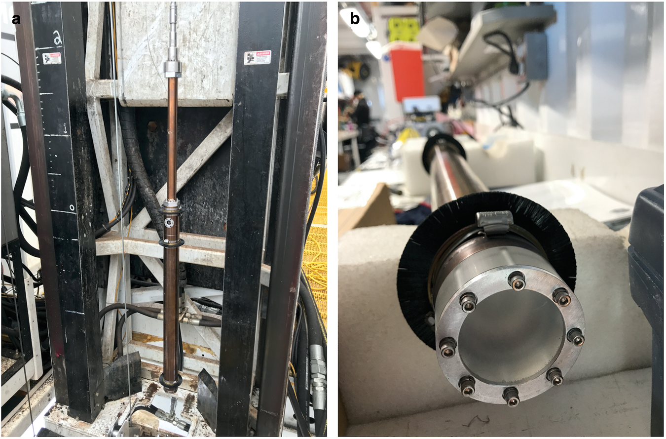
Fig. 11. Photographs of the laser dust logger prior to deployment in a borehole. (a) Logger positioned for wireline entry into a borehole. Round laser window is near the top of the sonde body. PMT ‘looks’ downward below the lower black nylon brushes. (b) Close-up view of the light receiver port at bottom of the sonde.
Data are taken while the device is lowered into and raised out of a liquid-filled borehole, providing a continuous replicate profile versus depth in a matter of hours. Although the absolute concentration and detailed chemistry of the dust in the ice vary locally, the detailed shape of dust records in different parts of Antarctica are remarkably similar. Insoluble particulate deposits originating from continental, volcanic or extraterrestrial sources are quite uniform over the continent and do not diffuse or significantly degrade after deposition. With high-quality dust logs, it is straightforward to correlate dust and tephra patterns with other known records in order to date boreholes over long distances quite precisely, independent of the snow accumulation rate. Local volcanoes can create large signals, but these are generally easy to distinguish.
In a liquid-filled borehole free of drilling debris, the device can be operated at logging speeds as high as 25 cm s−1 (15 m min−1) while obtaining full resolution. The winch used at the RAID test site (Mount Sopris 4WNA) was operable up to 9 m min−1. A winch payout encoder is used to record the depth, with a resolution of 1 cm. Optimally, the device is deployed at a steady speed for the best data quality. Using a load cell mounted on the winch, the cable tension is monitored closely for sudden drops or spikes while logging. In addition, to guarantee an optimal signal/noise ratio during deployment, the light intensity is adjusted to account for large changes in backscattering, particularly between bubbly and bubble-free (deep) ice. When the liquid in the borehole has uniform optical properties, this adjustment depends only on the bulk ice properties, which are usually smoothly varying with depth.
In hole 2, logging speed and light intensity were kept relatively constant until 485 m depth, beyond which it was impossible to lower the device due to the loss of tension on the cable. Presumably, a thick layer of chips prevented the dust logger from being lowered further.
Hole 3 appeared to contain chip layers along the full depth of the hole. For every few meters the tension dramatically decreased. Only by reducing the speed to a minimum, the device was successful in passing each chip layer. The average logging speed for hole 3 was <3 m min−1. Due to the chips, the light signal frequently saturated the instrument, resulting in continual adjustment of the intensity of light emitted. Large and sudden signal variations in the recorded signal hide dust layers, making data analysis more challenging.
Figures 12 and 13 show the data collected in the two holes. Comparing multiple logs from a single borehole (e.g. a trip down versus a trip up) or logs in adjacent holes (in this case, spaced ~100 m apart) allows for the identification of features that are characteristic of the ice (as opposed to borehole artifacts). This exercise is essential for validation at Minna Bluff, where a known dust profile with depth does not exist. The identification of well-recognized features in this case was more challenging than in other locations where boreholes are filled with a uniform liquid (see, e.g. typical logs for the South Pole; IceCube Collaboration, 2013). Further complicating the interpretation of the optical logs at Minna Bluff is a possibility that fast-flowing ice might contain disturbed layers against bedrock, especially between boreholes 2 and 3 despite close proximity to one another. In the case of the Minna Bluff records, there is general reproducibility both in runs within the same borehole (e.g. Fig. 12) and in correspondence to features between boreholes (Fig. 13). The gray vertical lines in Figs 12 and 13 highlight, as an example, some of the features that are recognizable between different datasets. This serves as a proof of concept that the dust logger can be used in holes drilled by RAID.

Fig. 12. Hole 2 dust log showing down versus up records (a and b, respectively).

Fig. 13. Dust logs of (a) hole 2 versus (b) hole 3 (both down).
Due to time limitations, we were not able to adequately evacuate the fluid-filled boreholes of ice cuttings, which is possible in principle by re-circulating drilling fluid through the ice-chip separation module. For future deployments, efforts will be made to eliminate or remove chip debris from the borehole to ensure that the device can reach the bottom and collect high-quality data over the entire depth of the hole.
Fluid overpressure and ice fracture risk
An important goal of AFT-3 was to measure the drilling fluid pressure at which the ice spontaneously fractures (hydrofracture). Future RAID operations will need to avoid hydrofracture, because a fracture in the ice generally precludes further fluid circulation and drilling, thus causing the hole to be abandoned. After successfully reaching bedrock, our plan was to intentionally hydrofracture the ice on our last hole while carefully recording the fluid pressure, yet we accidentally hydrofractured holes 1 and 3, and apparently also fractured hole 2 mechanically (as opposed to hydraulically). Fortunately, the surface fluid pressure in hole 3 was being carefully monitored at the time it hydrofractured, yielding an effective fluid overpressure value at a fracture of 1.41 MPa (204 psi), where overpressure is defined as the total fluid pressure minus the ice pressure. Total fluid pressure is calculated from the observed fluid (gage) pressure at the surface plus the mass of overlying fluid times the local acceleration of gravity, and ice pressure is calculated from the overlying ice mass times the local acceleration of gravity. This value of overpressure will be an important guide in determining fracture risk thresholds for future operations. A more detailed assessment of ice hydrofracture will be given in a separate paper.
Overall, these experiences show that ice fractures easily, so care must be taken in future RAID operations to avoid both high-fluid pressures and direct mechanical shocks to the ice with steel drilling components. It is expected that ice on the Polar Plateau, where RAID science drilling is planned, will be less brittle than Minna Bluff ice, which is under rather high stress due to the fact that it is a fast-flowing, thin and steep glacier. The high temperatures of Minna Bluff ice (−10°C at the bed) also make the ice relatively weak. Ice at RAID target sites on the Polar Plateau, in contrast, will be thicker and flowing much more slowly, creating less internal shear stress. Similarly, ice at RAID target sites on the plateau will also be stronger due to colder temperatures compared to Minna Bluff.
Lessons for deep polar ice drilling
The RAID drilling team made many field alterations to various drilling components, but other technical modifications were identified that should be implemented in the future. Among the problems encountered, the following lessons may be relevant to future deep polar ice drilling using RAID or other deep drilling systems more broadly.
Drill system rust
Rust was confirmed as a significant problem both for chip transport on steel augers, and as a potential contaminant in the drilling fluid. In the current RAID system, rust developed on auger flights and on the tubular bodies of drill rods in the presence of water formed from melted ice cuttings. Rust on steel auger flights impedes transport of cuttings and should either be eliminated by adopting rust-free auger materials or by removing built-up rust with abrasive tools. The latter is time intensive. Rust apparently developed on the inside and outside of steel NQ-size drill rods, particularly when stacked in the rod module for storage. We discovered during AFT3 that rust on drill rods was transferred to the drilling fluid and appeared to cause formation of an emulsion between ESTISOL™ 140 (a hydrophobic, oil-like substance) and water, which significantly reduced the effectiveness of the melting–coalescing process during fluid recirculation. As applied to the RAID system, it is important to minimize or eliminate rust from all drilling components. Appropriate remedies include coating all steel surfaces that are in contact with drilling fluid or switching to non-ferrous materials.
Ice fracture risk
As noted above, hydrofracture is a known problem, based on RAID's experience during AFT2 and AFT3, and from the experience of other polar drilling systems (e.g. ASIG drill operated by the IDP at Pirrit Hills; Kuhl and others, Reference Kuhl2020). Fracturing of ice can occur by multiple causes, including fluid overpressure, pulses of fluid passing through the system after blockages are cleared and percussive shock from loading ice with the drill string. One approach to mitigating this risk is to design a device that monitors weight-on-bit and automatically stops penetration if the weight-on-bit dramatically increases (indicating that the drill has encountered an obstacle such as a rock). This would reduce the risk of an ice fracture when the bit snaps past the rock and releases a large amount of the steel pipe's gravitational energy all at once in a percussive shock on the ice. Similarly, improvements to fluid transport will reduce the risk of overpressure due to blocked flow.
Fluid overpressure
As demonstrated during AFT3, a PRV is a critical in-line component for the management of fluid pressure, but it should allow for variable pressure settings, be less susceptible to clogging of the valve mechanism with ice cuttings and have an appropriate pressure range.
Separation of ice cuttings and drill fluid
Both the screen shaker and melter/coalescer were demonstrated to be effective at physical separation of ice cuttings and drilling fluid. However, the screen shaker required vigilant oversight and the coalescing process was less effective in the presence of a rust-water emulsion (see above). An alternative is to substitute the screen shaker with an appropriately sized and designed rotating drum screen or other type of filtration system for more effective separation of cuttings from drilling fluid.
Lightweight drilling components
Some of the drilling components (hose swivel, diverter, etc.) were acquired as commercially available parts used in the hydrocarbon exploration and production industry. These were specified in part to handle potential gas blow-outs and are much heavier than required for RAID. Smaller and lighter alternatives, possibly fabricated from aluminum, should be evaluated for greater ease of use.
Cutting tools
Tools used for ice borehole cutting and ice and rock coring were custom designed for RAID. As noted earlier, some problems were encountered with refreezing and packing of ice chips in tool ‘waterways’ that allow the all-important drilling fluid to pass through. For example, our coring assembly has circular openings that allow fluid carrying ice chips past the latch-head and upward into the drill pipe; these openings are suitable for use with conventional drilling muds transporting rock flour, but they are subject to clogging with ice chips and/or mixtures of ice and rock particles. Modifications are required to enlarge these openings as much as possible and increase the annular space between the coring tool and the core barrel, which will allow for better flow and less susceptibility to blockage.
Prospects for plateau drilling
The testing at Minna Bluff demonstrated the effectiveness of the integrated system to drill rapidly through thick ice and penetrate across the glacial bed to take cores of bedrock. The particular challenges at this site also show, however, that there are two major aspects of the RAID system that should be improved in order to make future drilling more reliable. First, to avoid blockages and packing of cuttings, all down-hole tooling should be redesigned so that adequate waterways are made large enough to allow for effective passage of fluid–ice-cutting mixtures. Some of the cutting heads and coring tools designed for RAID were adapted from the rock-coring industry. These typically produce relatively fine cuttings by frictional abrasion and are transported by a viscous drilling mud. By producing intentionally coarse ice cuttings, or by unexpected refreezing of melted cuttings, the ice particles transported in drilling fluid showed a tendency to clog or pack the tool ‘waterways’. Further evaluation and redesign of ice-cutting and coring tools are clearly warranted based on the experience at AFT3, with a goal to cut ice boreholes at a rate of 3 m min−1 (design limit of the LF-230 drill rig). Second, the FRS should be evaluated and retrofitted where necessary in order to prevent water and/or ice from entering the supply side tanks and return lines into the borehole. These problems may be intrinsic to the drilling experience at Minna Bluff, where ambient temperatures are warmer than those in which RAID was designed to operate. Continued refinement of the fluid transport system to increase radii of hose bends and couplings, enlarge hose diameters and ensure that fluid transport is kept <0°C everywhere will be necessary for sustained future field operations.
From a longer-term perspective, AFT3 demonstrated the high value of field experimentation with a working prototype. As an entirely new approach to deep ice drilling and subglacial access coring, many of the bespoke drilling components designed for RAID were impossible to test in any other setting than in thick Antarctic ice. Our three Antarctic Field Trials (AFT1 in 2016–17, AFT2 in 2017–18 and AFT3 in 2019–20) collectively provided the opportunity to quickly learn as many valuable lessons as possible. During the development of a new system like RAID, we found that it is often better to take the system into its operating environment without delay in order to get rapid feedback on what works and what does not. When problems arise, getting information quickly helps avoid following unproductive paths and the time-consuming (and expensive) process of over-engineering to mitigate all possible outcomes. Active field experimentation leads to quick progress on a steep learning curve. Thus, the earlier field trials, while falling short on some goals, were extremely valuable and highlighted the challenges and mistakes that needed to be overcome in order to achieve success at AFT3. Because Antarctic field seasons are short, it is not surprising that early challenges arose which prevented completion of first-order goals during AFT1 and AFT2. Building on lessons learned, AFT3 has demonstrated that as a working prototype RAID has the capability for which it was designed.
In many respects, drilling operations on the high Polar Plateau will be less of a challenge. The more extreme conditions, while harder on people, will actually make ice drilling and bedrock coring more straightforward due to the colder surface temperatures to be encountered. Colder air temperatures will ensure that drilling fluid reservoirs at the surface will be adequately chilled prior to introduction in boreholes, mitigating down-hole high temperature advection and surface melting as was experienced at Minna Bluff. In addition, the most likely sites for achieving scientific goals on the Polar Plateau will overlie cold (hence, stronger), low-stress ice, reducing significantly the risk of hydrofracture due to fluid overpressure. Conversely, the extreme cold of the plateau environment will lead to an increase in kinematic viscosity of ESTISOL™ 140 (Sheldon and others, Reference Sheldon, Popp, Hansen and Steffensen2014), which may negatively impact travel time of the wireline tools, chip recovery, pump efficiency, etc. Based on a balance of mitigations, we nonetheless advocate for high-altitude plateau drilling tests as the next step in RAID development.
Acknowledgements
Successful drilling at Minna Bluff in 2019–20 was accomplished through the hard work and persistence of the RAID Drilling Team, composed of Chris Peone, Thor Hall, Don Kirkpatrick, Owen Little, David Lundberg, Ray Martin, Shawntel Stapleton and Anthony Vecchiarelli. We thank Chris Delahunty, Tanner Kuhl, Karen Marshall, Claudia Rock and Blaise Stephanus for their profound dedication during birth and development of the RAID system. We are also grateful for the technical support provided by Krissy Slawny and the US Ice Drilling Program. Bob Hawley graciously loaned his optical televiewer. Outstanding field operational support for AFT3 was provided by Matthew Kippenhan, Rebecca Ricards, Ioffe Lee and the Minna Bluff camp and traverse staff, including Tyler Gilbertson, Hailey Gruber, Terry Jordan, Joey Preston and Martha Sortland. Very helpful review comments were provided by editor Pavel Talalay, Tanner Kuhl and two anonymous reviewers. The RAID development project is supported by the Division of Polar Programs at the US National Science Foundation with awards to Goodge (1242027 and 1419935) and Severinghaus (1242049 and 1419979).


 Open access