


1. Introduction
Ice-core drilling on polar ice sheets is a research technique that was started in the mid-20th century. The resulting research findings are of notable scientific importance. The dust and suspended particulate in the Earth’s atmosphere have been deposited on the Antarctic ice sheet through flow from the atmosphere, and capped by the growing ice shields. Additionally, the Antarctic ice sheet records information on variation of global climate and the history of climatic and environmental change caused by the influence of human activities. The Antarctic ice sheet is consequently known as the ‘time capsule’ (Reference MotoyamaMotoyama, 2007). An ice core from the polar ice sheets is one of the best mediums for researching environmental, biological, chemical and physical processes in the Earth’s system, with its advantages of high resolution, a large amount of information, high fidelity, long time series and high levels of cleanliness. Through ice-core studies, climate-change series of hundreds of thousands of years can be built. Ice-core studies provide an excellent method for investigating the past variation of global climate, monitoring the status and forecasting the future. Ice-core studies have made a major contribution to research on the variation of global climate (Reference QinQin, 1991; Reference PetitPetit and others, 1997; Reference YaoYao, 1998; EPICA Community Members, 2004, 2006; Reference Ren, Xiao, Hou, Li and SunRen and others, 2009).
China formally implemented its first deep ice-core drilling project DK-1 in Antarctica in January 2012. The drilling site selected was at the Chinese Kunlun station (80°25′01″ S, 77°06′58″ E), located in the Dome A region (Fig. 1), the highest plateau of the Antarctic ice sheet (Reference Tang, Xun, Li, Cui and LiTang and others, 2012a). The elevation is nearly 4100 m, the average ice-sheet thickness is ∼3100 m and the average annual temperature is −58°C. Horizontal movement of the ice is minimal and the snow accumulation rate is as low as 16 mm w.e. The region is the site with the lowest average annual temperature and smallest average annual snow deposition on Earth. Estimation of a depth-temperature distribution with a steady-state ice-dynamics model indicates that the ice at 3100 m depth might be >1.1 Ma old, with a temperature of −8.4°C (Reference Hou, Li, Xiao and RenHou and others, 2007). Therefore, the Dome A region presents an opportunity to obtain the oldest continuous ice core with an age exceeding 1 Ma (Reference Xiao, Li, Hou, Allison, Lingen and RenXiao and others, 2008). This discovery aroused great interest within the international scientific community (Nature, 2006; Reference JonesJones, 2007; Reference Tang, Sun, Li, Li and CuiTang and others, 2012b).

Fig. 1. Location of Kunlun station and other deep drilling sites in Antarctica.
The Chinese First Deep Ice-Core Drilling Project DK-1 is a path-finding program planned to be completed before 2018. The first season of the project was carried out by the 28th Chinese National Antarctic Research Expedition (CHINARE) team in January 2012, with the main task of constructing a pilot hole. In the next season, in January 2013, the 29th CHINARE team installed a deep-ice ‘wet’ drill system and started coring operations. Due to logistical problems, drilling was not conducted in the 30th CHINARE but is planned to be continued in the following four seasons from 2014 to 2018.
2. Logistics and Drilling-Site Construction
The logistics work was begun by the 26th CHINARE team in January 2010. All cargo was shipped to Zhongshan station and unloaded on the Antarctic coast by the Chinese polar icebreaker Xuelong. The construction material for the ice-drilling site and the drill equipment were loaded on sledges and transported from Zhongshan station to Kunlun station at Dome A, towed by snow vehicles for ∼1260 km (Fig. 2). Every season, about eight or nine vehicles were used to transport the material, drill equipment, fuel oil, food, generating equipment and camp containers (Fig. 3). Two types of vehicle are used to haul the cargo sledges: a Pisten Bully 300 vehicle with a maximum carrying load of 30–35 t for light cargo sledges, and a Caterpillar Challenger MT865B with a maximum carrying load of 50–60 t for heavy cargo sledges. Because of extremely severe weather conditions with temperatures down to −30°C, and the lack of roads in inland Antarctica, the traverse from Zhongshan station to Kunlun station typically takes ∼20 days (Fig. 4). Usually the traverse starts relatively late, in mid-December, due to logistical problems.

Fig. 2. Traverse route from Zhongshan station to Kunlun station.

Fig. 3. Transportation traverse ready to go (16 December 2012; inland team departure point 8 km from Zhongshan station).

Fig. 4. Severe weather and road conditions on the way from Zhongshan station to Kunlun station: (a) traversing in blowing snow with low visibility; (b) snow bridge collapse after crossing crevasse on route; (c) sastrugi (∼1 m high) on route; and (d) heavy soft snow area inland (∼1000 km from Zhongshan station).
During the 2009/10 season, construction of the main field drilling site was completed. To prepare the drilling trench (40 m × 5 m × 3 m) beneath the surface, >700 m3 of snow was excavated. In total, ∼20 t of wooden base material and 36 t of steel structure were used to construct the drilling trench framework (Fig. 5). The framework included 40 pillars and 19 steel roof trusses.

Fig. 5. Construction of the drilling trench framework. (a) Drilling trench excavation; (b) steel structure installation; (c, d) roof installation; and (e) exterior of drilling trench.
Through the 2010/11 season (27th CHINARE), the base of the floor was paved and most of the pit for the mast slot was excavated. For the floor construction, wooden beams with sectional dimensions of 200 mm × 200 mm were used as base beams, and wooden braces with sectional dimensions of 50 mm × 100 mm were used as beam supports. The wooden beams and braces were watered to freeze and fix to the snow surface. Polyethylene plastic foam insulation boards were paved between the beams (Fig. 6a). Compatibility of the insulation boards with the suggested drilling fluid, n-butyl acetate, was a concern. Spilling the fluid on the floor could eventually destroy the insulation. It was well known that n-butyl acetate is a very aggressive solvent (Reference Talalay and GundestrupTalalay and Gundestrup, 1999). There are no elastomers that can operate in n-butyl acetate for a long time. On the other hand, some plastics (e.g. polypropylene, Teflon, polyethylene, Kevlar, nylon) are recommended materials for using with n-butyl acetate, as they are unlikely to be destroyed in the fluid. Polyethylene foam board was therefore chosen as the isolation material for the drilling shelter floor. Simple short-term tests confirmed that n-butyl acetate has no effect on this material.

Fig. 6. (a) Floor base made from insulated paving and wood beam. (b) Mast pit excavation.
After construction of the floor base, a sector-shaped mast pit (7.4 m × 0.6 m × 9.6 m) was excavated (Fig. 6b). During the 2011/12 season (28th CHINARE), the interior infrastructure of the drilling site was completed and wooden stairs and an entrance were built.
During the 2012/13 season (29th CHINARE) a control room, a maintenance workshop for the drilling trench and a core-processing room were excavated and constructed. The electrical system was installed, and the mast pit was deepened to the final depth of 9.6 m. The control room and the workshop were built with a steel frame and insulation boards (Fig. 7a and b). The core-processing trench, 40 m long and 8 m wide, was excavated and covered by the same kind of framework as the drilling trench (Fig. 7c). The drilling and core-processing trenches were connected by an 8.7 m × 3 m tunnel. A generator with a nominal power of 80 kW was built into a specially designed container installed at the surface. The generator was transported on a sledge. It provided power for drilling, auxiliary equipment, heating and lighting.

Fig. 7. Construction of (a) control room, (b) maintenance workshop and (c) core-processing room.
By the end of the 2012/13 summer season, all the materials and equipment had been installed in the appropriate place and the drilling site construction had been completed (Fig. 8).

Fig. 8. Schematic of drilling trench.
3. First Drilling Season: 2011/12
Operations during the first drilling season at Kunlun station, 2011/12, were delivered within 21 days (including 16 days for pilot-hole construction) in three phases (An and Li, unpublished): (1) shallow drilling of the pilot hole, (2) reaming and (3) casing setting (Fig. 9; Table 1).

Fig. 9. Working events during the first drilling season at Kunlun station: (a) lowering shallow drill; (b) lifting the drill; (c) cleaning the drill and removing the core; and (d) core processing.
Table 1. Progress of the first drilling season at Kunlun station

3.1. Shallow ice-core drilling
The first phase included conventional shallow drilling with the electromechanical auger ice-core drill (Model D-3, 600M type) which was purchased by the Polar Research Institute of China from the Geo Tecs Company, Nagoya, Japan. The drill’s design concept has been used before by other shallow ice-core drilling operators. The drill contains cable termination, leaf spring anti-torque system, driven section and double core barrel. Chips, lifted by the inner auger through the window on top of the tube, drop on the plastic plate that separates the core barrel into two parts: one to hold the core and the other for chips (Table 2).
Table 2. Technical parameters of electromechanical shallow ice-core drill (Operating manual for the shallow ice core drill type D-3. 2011. Geo Tecs Co. Ltd, Nagoya)

In total, 118 coring runs were undertaken using a drill bit of 135 mm outer diameter (OD) and 96.4 mm inner diameter (ID). The final depth of the ‘dry’ hole was 120.79 m, with an average core run of 1.024 m (Fig. 10). The total drilling time was 51.5 hours. The depth of the coring run decreased from 1.2–1.4 m to 0.5–0.9 m, deeper than the firn/ice transition (∼100 m) because of the increasing density and tensile strength of the upper snow/firn/ice structure. The drilling efficiency and the core length of each run also decreased with depth (Fig. 11).

Fig. 10. Drilling process (‘dry’ auger drilling).
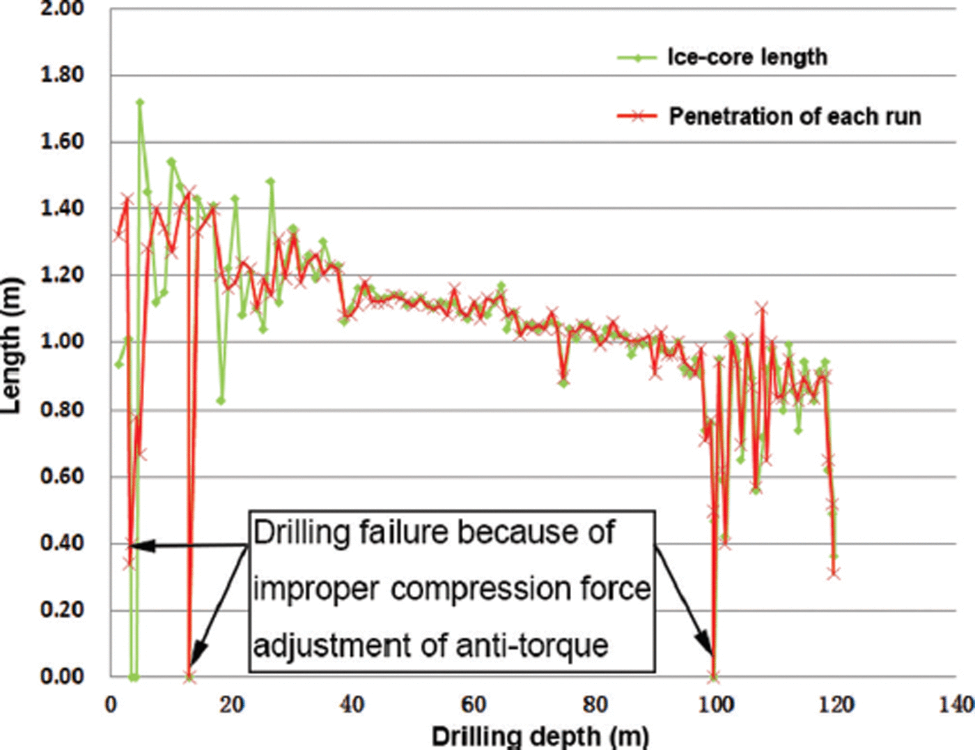
Fig. 11. Run and core length vs depth (‘dry’ auger drilling).
The drill bit rotation speed down to 20 m depth was maintained at ∼40 rpm. Beyond 20 m, it was increased to 60 rpm (max 80 rpm), and the penetration rate was controlled in the range 6–8 m h−1 (Fig. 12). At depths exceeding 100 m, the penetration rate dropped to 4–6 m h−1. Under normal drilling conditions, the motor current was in the range 0.6–1.2 A. When the chip chamber was full, however, the current could exceed 1.2 A and the drill process had to be stopped. Cutters with a 35°C rake angle were used.

Fig. 12. Penetration rate vs depth (‘dry’ auger drilling).
During the drilling process, some problems were encountered:
In the upper snow formations, the core was not always recovered, because of the loose formation. When the lifting speed was reduced, it became possible to recover the core. Several times the anti-torque system had to be adjusted because leaf springs slipped in the hole or were too tight, and the drill could not reach the bottom to cut the ice.
The position of the plastic plate that separates the chip chamber from the core barrel requires a means of achieving finer adjustment. The plate position was changed by leveraging its position with a wooden stick and using line-of-sight and experience. At the beginning, the ratio between core barrel and chip chamber was ∼1 : 1. With increasing depth and snow–firn density, this ratio was adjusted to ∼1 :1.17 from a depth of 63 m to the final depth.
During the drilling process, the cutters were changed twice because degradation of the penetration rate indicated that the cutting edge was blunt. After changing cutters, the penetration rate was restored.
Finally, an ice-core fracture problem was identified when drilling at greater depths. Down to 73 m depth, the recovered ice core was usually in one piece, but further down the core was broken into two or three pieces at right angles to the axis because of higher ice brittleness. There were visible fracture cracks at the surface of the core.
3.2. Reaming
The second phase involved reaming the hole in three steps (Table 3). The same shallow electromechanical auger ice-core drill was used, but, instead of the conventional double core barrel, a special reamer with a chip container was installed. The bit rotation speed was adjusted to 11 rpm, and the reaming had a higher penetration rate than core drilling (Fig. 13). As with the shallow ice-core drilling, the reaming penetration rate decreased with depth.

Fig. 13. Reaming penetration rate vs depth.
Table 3. Reaming parameters

To avoid dropping the chips during reaming, duct tape was wrapped around the top of the chip container to seal the clearance between it and the borehole wall. This action reduced the problem but did not completely solve it. As some of the ice cuttings dropped onto the bottom of the hole during the reaming process, recovery of the ice chips was carried out after each reaming size, using the standard configuration of the shallow ice-core drill. After removing the ice chips, a 30 mm long core was obtained, which indicated that the bottom was clean. The final depth of the pilot hole after cleaning was 120.79 m.
The borehole structure achieved at the end of the season is shown in Figure 14. The lower part of the hole (∼16 m) was uncased in order to ensure that the anti-torque system fitted to the deep ice-core drill could contact with the borehole wall and hold the upper non-rotated part of the drill.

Fig. 14. Borehole structure as of 22 January 2013. Ø is diameter.
3.3. Casing
Seventeen 6 m long fiberglass pipes used for casing were installed in the pilot hole to ∼100 m depth to prevent drilling fluid from leaking into the permeable snow-firn formation during drilling. The average speed for lowering the casing pipe was kept at 0.3 m min−1. The pipes were screwed together with a four-threaded connection (M218 × 6 mm) and sealed with fluoroplastic tape.
4. Second Drilling Season: 2012/13
The second field season, 2012/13, was shortened to only 13 days. Excavation of the mast pit took five of these days. Activities in the second season can be divided into three phases: (1) installation of the deep ice-core drilling system; (2) equipment connection, debugging and testing; and (3) start of deep ice-core drilling (Fig. 15; Table 4).

Fig. 15. Working events during the second drilling season at Kunlun station: (a) drill rig assembly; (b) fluid back-flow slot installation; (c) lowering the drill; and (d) cleaning the drill and removing the core.
Table 4. Progress of the second drilling season at Kunlun station

4.1. Equipment installation
To continue ‘wet’ deep drilling, the following equipment was installed in the drill trench:
-
1. Mast and base including the mast top with top pulley and turnabout pulley on the base;
-
2. Winch, on which 4000 m of armored cable have been coiled through a braking device with dynamometer (spooling cable tension was kept at ∼5 kN);
-
3. Electromechanical CHINARE/Japanese Antarctic Research Expedition (JARE) deep ice drill, jointly developed by the Polar Research Institute of China and the Geo Tecs Company, Nagoya, Japan (Table 5);
-
4. Control system (power supply, winch control panel, drill motor control panel);
-
5. Auxiliary equipment including ice working tables, chip centrifuge, drill and core clean devices, and ventilation system.
The design of the electromechanical CHINARE/JARE deep ice drill is similar to that of the JARE deep drill used at Dome F (Reference MotoyamaMotoyama, 2007), except for the size of the chip chamber, the anti-torque system and some other parts. For example, the chip chamber of the CHINARE/JARE deep ice drill is shorter by 533 mm and larger in ID by 2 mm than the JARE drill.
Table 5. Technical parameters of electromechanical deep ice-core drilling rig (Operation/maintenance manual for CHINARE/JARE deep ice core drill system. 2011. Geo Tecs Co. Ltd, Nagoya)

4.2. Equipment connection, debugging and testing
All electrical and communication systems were connected and checked. The external sensors (load cell and temperature gauge), limit switch and depth-meter were installed and connected to the control unit. After debugging, the deep ice-core drill was lowered and lifted several times in the hole. The relationship between the cable setting speed with a cutter load and the rotation motor load was tested. A short 30 mm long testing run was carried out without drilling fluid.
Following the test run, 400 L of drilling fluid (n-butyl acetate) was poured into the hole to 104 m depth. The drill was lowered and the change of cutter load when the drill was in the fluid and at the bottom was measured. The temperature at the bottom (120.79 m) was measured as ∼–50°C. The drill inclination at vertical free fall was acceptable (x: − 1. 4 to −1.0°, y: −0.9 to −0.5°).
4.3. Start of deep ice-core drilling
Because of the short time in the field, only three runs, with a cumulative depth of 10.45 m, were carried out (Table 6). The coring length was 10.99 m including an ice core remaining from the previous season (Fig. 16). During the ice-core drilling process, the lowering speed was kept at 0.3 ms−1, and the lifting speed at 0.34 ms−1. The lifting load with ice core and chips was ∼1.6 kN, while the force of ice-core breaking reached 2.4 kN. During the drilling process, the drill inclination was −1.6 to −1.0° in the x direction and 1.1 to −1.0° in the y direction.

Fig. 16. Ice cores from ‘wet’ drilling (interval 120.79–131.24 m).
Table 6. Deep ice cores

Drilling was achieved with a cutter load of 30–60% of the drill weight and a motor current of 2–3 A. The highest motor rotation speed of ∼4000 rpm, which corresponds to a drill head rotation speed of 50 rpm, gave higher drilling efficiency. During the deep ice-core drilling process, some problems were encountered:
The tensile force of the anti-torque spring was adjusted as required. At the beginning of the first run, the motor current was <2 A, which is outside the normal working current range of 2–3 A. It was identified that the anti-torque spring had been adjusted to be too tight. When the drill was set near the bottom, the springs were blocked at the point where the first reaming finished. It was difficult to lower the drill any further. After lifting the drill and checking, it was found that the spring had been deformed. After adjustment, the cutter load kept increasing to 80% of the drill weight. It was concluded that the springs had been adjusted excessively. Finally, a proper tensile force was set, then the drilling process became normal.
Generally, the control system worked reliably except for the d.c. supply of the driven motor. At the beginning of the second run, the electrical supply relay was burnt out. After changing the relay, the motor worked normally.
During the drilling process, the frequency converter often stopped after a period of operation. It was found that when the temperature of the converter box increased, overheating protection was activated. Simply opening the cover of the box solved the problem.
5. Conclusions and Future Plans
In January 2012 the Chinese Deep Ice Core Drilling Project DK-1 was formally started. After installation of the casing, three runs of ‘wet’ ice-core drilling were carried out and a depth of 131.24 m was reached. Generally, all systems and components worked well.
To speed up drilling progress, the logistics for Kunlun station are planned to be modified so that the field season duration can be increased to 1.5–2 months. Drilling to the bedrock down to nearly 3100 m depth is expected to be completed during the next four seasons. The successful fulfillment of drilling tasks during the first two seasons has established a firm foundation for future work.
Acknowledgements
The fieldwork and research introduced in the paper were supported by various funds, including Chinese Polar Environment Comprehensive Investigation and Assessment Programmes (No. CHINARE2014-02-02 and No. CHINARE2014-94-02-07), Public Science and Technology Research Funds Projects of Ocean (No. 200805001), National Nature Science Foundation of China (No. 41327804) and Chinese Polar Science Strategy Research Fund – Young Talent Fund (No. 20120313). The field personnel overcame the major difficulties of lack of oxygen and extremely low temperatures in inland Antarctica. We thank H. Motoyama of the National Institute of Polar Research, Japan, and Japanese drilling experts Y. Tanaka, M. Miyahara and A. Takahashi for help with the drilling technology design and training. Authors also thank the teammates and machinists of the 28th and 29th CHINARE team who provided excellent logistic support for the fieldwork of the Chinese Deep Ice-Core Drilling Project. We also acknowledge David Blake of the British Antarctic Survey for editing the paper.


