


Introduction
With the development of AI technology, it has become a great goal for designers to realize creative design activities with AI. The goal cannot be achieved without a well-developed design methodology as its theoretic foundation. The development of scientifically based, explicitly organized, rational, and systematic methods and tools is required (Cascini and Montagna, Reference Cascini and Montagna2020). And creative thought to produce new and exciting products, systems, and services (Fu et al., Reference Fu, Fuge and Brown2018) is needed.
Axiomatic design (AD) provides a theoretical basis upon which logic and rational thought are followed and mathematically expressed throughout the entire design process (Suh, Reference Suh1990). As a design methodology, AD postulates fundamental axioms that govern the design process and furnishes tools effective for implementation. AD theory has become a basic theory, largely due to the extensive application of AD theory in various fields. Nevertheless, the strong universality also leads to weaker pertinence. While providing a solid framework for the better organization and generalization of design knowledge, however, inexperienced practitioners of the AD theory find it difficult to follow or apply the principles in their design which inadvertently often leads to misunderstanding and skepticism (Nordlund et al., Reference Nordlund, Kim, Tate, Lee and Oh2016), due to the following reasons:
(1) The AD theory provides no definitive descriptions for all the elements in the four domains that are well-defined in the theoretical framework. As a result, it is difficult for designers to establish a minimum set of independent, solution neutral functional requirements that are all at the same level of abstraction.
(2) The zigzag mapping process for design is defined in AD, however, approaches essential to guiding the process are unavailable, thus rendering ambiguity and confusion when searching for design solutions and risking discouraging broad-base thinking that would otherwise foster innovation.
(3) The design parameters in AD are usually defined as concrete structures, making it difficult to expand the design solutions systematically.
The aim of the paper is to improve the design procedure in AD with better defined elements in domains and explicit approaches to guide the design process. Furthermore, the possible for expanding design solutions is also explored. These issues are addressed in the article with the fundamental ideas of Extenics. The improved design procedure makes it easier for both designers and computer to implement and it can supply a better foundation for artificial intelligence in design.
Literature review
AD has been widely studied and applied to many areas. According to the classifications made by Kulak et al. (Reference Kulak, Cebi and Kahraman2010), AD is found practical and effective in product design (Tang et al., Reference Tang, Zhang and Dai2009), decision making (Kahraman and Çebı˙, Reference Kahraman and Çebı˙2009; Cebi et al., Reference Cebi, Celik and Kahraman2010), computer software design (Girgenti et al., Reference Girgenti, Giorgetti, Citti and Romanelli2015; Kandjani et al., Reference Kandjani, Tavana, Bernus, Wen and Mohtarami2015), system design (Babur et al., Reference Babur, Cevikcan and Durmusoglu2016), knowledge service (Chen et al., Reference Chen, Li, Fan, Zhou and Zhang2016), CIM systems design (Delaram and Valilai, Reference Delaram and Valilai2018), and many others.
Besides, many efforts have also been made to improve AD theory, including revising the theoretical framework and introducing other ideas into the methodology. After the axiomatic design principles made their first debut, Suh (Reference Suh1998) provided a theoretical basis for the design of systems as well as the flow diagram for system architecture. Theorems therein stated that the quality of a design depended on the selection of FRs (functional domains) and the mapping from one domain to another. In 2005, Suh (Reference Suh2005) suggested that complexity was a measure of uncertainty in satisfying the FRs within their design range. The four types of design complexity established in that work have since been accepted as the fundamental concepts of complexity theory. Engelhardt (Reference Engelhardt2000) presented an approach for quality improvements and problem solving by combing AD, quality control tools and designed experiments. Su et al. (Reference Su, Chen and Lin2003) applied the analytic hierarchy process (AHP) to measure the coupled design tasks that were generated using AD. The effort realized an algorithm applicable to finding the best processing sequence. To explore more proper descriptions for function models, Müller et al. (Reference Müller, Isaksson, Landahl, Raja, Panarotto, Levandowski and Raudberget2019) proposed an enhanced function-means model which can increase the amount and variety of explored alternatives.
After reviewing the disadvantages of AD and design structure matrix (DSM), Tang et al. (Reference Tang, Zhang and Dai2009) integrated the two theories to augment the conceptual design process as a recursive interaction of AD's design matrix and the corresponding DSM. Thompson (Reference Thompson2013) introduced a new method that structured the requirement process in AD where a requirement classification system, a stakeholder classification system, and a table to visualize the mapping between the stakeholders and their requirements were included. Du et al. (Reference Du, Cao, Chen and Wang2013) developed a novel reuse-oriented redesign method for used products based on AD and quality function development (QFD) to standardize and optimize the redesign process. Mabrok et al. (Reference Mabrok, Efatmaneshnik and Ryan2015) provided a framework that included nonfunctional requirements as well as functional requirements into the mapping between domains by reusing the functional domain as a requirement domain and extending the standard AD matrix to a block matrix called an extended design matrix. The integration of AD and TRIZ was also a typical topic over the years for the reason that AD is applicable to analyze problems and structure the corresponding design process while TRIZ is apt in solving contradictions in the design of end products or other deliverables (Borgianni and Matt, Reference Borgianni and Matt2016). Function means tree (FMT) (Robotham, Reference Robotham2002) is a conceptual design method for generating design schemes. Through the establishment of FMT, the models of function can be described in detail which in turn helps with describing the mapping process. However, FMT stops short at providing a unified definition for the elements in the AD domains. To improve the zigzag mapping process, Chen et al. (Reference Chen, Hu, Qi and Chen2020) established a computer-aided approach with distributed design resource environment. Considering the interactions between a smart system and the environment, Gui and Chen (Reference Gui and Chen2021) proposed a scenario-integrated approach for functional design of smart systems. Li et al. (Reference Li, Song, Mao and Suh2019) applied Extenics to describe the coupling problems in AD, showing that the two theories can be complementary to each other. However, the design procedure is not considered. The most important and innovative process of AD theory, the mapping procedure is still not accelerated efficiently.
Brief overviews of the design theories
Axiomatic design: a brief overview
The ultimate goal of AD is to establish a scientific basis for design and to improve design activities by providing designers with a theoretical foundation based on logical and rational thought processes and tools. In AD, the design process is expressed as a mapping between four domains: Customer Domain {CAs}, Functional Domain {FRs}, Physical Domain {DPs}, and Process Domain {PVs}. By the concept of functional basis, the FR in the functional domain is a verb–noun pair that describes an action while the DP in the physical domain is the entity of the corresponding function (Stone and Wood, Reference Stone and Wood1999). The decomposition process formalized by the mapping process enables a systematic flow from the creation of concepts to detailed designs.
For each pair of the adjacent domains, the domain on the left-hand side represents “What we want to achieve”, while the one on the right-hand side represents the design solution of “How we propose to achieve it” (Suh, Reference Suh2001). The design method progresses by zigzagging between domains and decomposing the design problem. The mapping process between the domains can be expressed mathematically. The relationship between FR and DP can be written as
 $${{\rm FR}} = [ A] { {\rm DP}}, $$
where [A] is called the design matrix.
In AD, the mapping between FRs and DPs can be generated through database, analogical case, and reverse engineering. At a given level of design hierarchy, a set of functional requirements exists. Mapping between domains can oftentimes be vague and capricious to the designer. At present, this process mainly depends on the designer's subjective judgment and knowledge storage.
According to the concept of design synthesis in AD theory, the synthesis process reconciles the conceptualization of a set of design parameter primitives DP with the satisfaction of a set of FR as
 $${\rm DP} = f_s( {{\rm FR}, \;{\bf {DP}}} ), $$
where “fs (⋅, ⋅)” describes the designers’ mental process of generating the DP to satisfy FR with a set of design parameter primitives DP in their mental conceptualization (Farid, Reference Farid, Farid and Suh2016).
AD also provides two axioms for evaluating the design scheme: Independence Axiom and Information Axiom.
-
Independence axiom: Maintain the independence of the functional requirements (FRs).
-
Information axiom: Minimize the information content of the design.
According to AD, a design is considered an ideal design if each off-diagonal element is zero, that is, Aij = 0 (i ≠ j). It means that FRi is completely defined by DPi. In case the design cannot be an ideal design, the off-diagonal elements should be much smaller than the diagonal elements to achieve a robust design, that is, Aii ≫ Aij, meaning that the corresponding DPi is the main design parameter that satisfies FRi (Suh, Reference Suh2001).
The mapping process and the axioms lay the foundation for the scientific framework of design. By following AD, a designer can obtain a successful new design using existing design tools and software, or diagnosing and rectifying an existing design.
Extenics: a brief overview
Extenics was first formulated by Chinese scholar Cai in Reference Cai1983. In the past 38 years, a large number of scholars have gradually gathered to study the basic work of realizing this ideal (Yang et al., Reference Yang, Zhang and Cai2002). The formal system is put forward to formalize affairs, objects, relations, information, and knowledge, and the extension models are established (Cai et al., Reference Cai, Yang and Lin2003a). By studying the laws of dealing with contradictions, the extension theory and extension innovation methods are proposed. Extenics has been applied in engineering, information, mechanical, management, and many other fields (Wang et al., Reference Wang, Yu, Zeng and Wang2007; Li et al., Reference Li, Liu, Chen and Zeng2017; Liu et al., Reference Liu, Liu, Lyu, Zhao and Xu2021; Ren et al., Reference Ren, Gui, Zhao, Zhan, Wang and Zhou2021).
Extenics is an emerging multidisciplinary theory with formalized, logical, and mathematics characteristics, which explores the extensions of matters and objects, and the formulation of rule and method of innovation (Cai, Reference Cai1998, Reference Cai1999). Extenics consists of the Extension theory, Extension innovation method system, and Extension engineering (Yang, Reference Yang2017).
The core of Extenics theory is basic-element theory, extension set theory, and extension logic (Cai et al., Reference Cai, Yang and He2003b). The basic-element theory includes the concepts of basic-element and complex-element, Extensible analysis theory, Conjugate analysis theory, and Extension transformation theory. The Extension set theory includes the Extension set and Dependent function. Extension logic includes the Extension models, Extension reasoning, and so on. All the contents constitute the framework of Extenics and one can find more detailed introductions in the reference (Yang and Cai, Reference Yang and Cai2013). Extenics provide an innovative method system to analyze and solve problems from the perspective of constituent elements of the problem based on the basic-element models, which is applied in this paper to overcome the design problems.
A methodology system named Extension innovation method system is established in Extenics which is an effective methodology of analyzing, transforming, deducting, and judging contradictory problems and finally generating strategies to solve them. The extension innovation method system includes the Extension thinking modes, Extensible analysis methods, Conjugate analysis methods, Extension transformation methods, and Extension set methods.
The extension thinking mode is defined in Extenics to help one with creative thinking, which is divided into rhombus thinking mode, reversed thinking mode, conjugate thinking mode, and conductive thinking mode, which can be applied as guidance during the design process (Wang et al., Reference Wang, Ma, Wang, Kemi and Yu2019). The extensible analysis methods investigate the extensibility of matters, affairs, and relations. Conjugation analysis method analyzes the matters, affairs, and relations from the nonmaterial and material aspects, the soft and hard aspects, the latent and apparent aspects, as well as the negative and positive aspects. Extension transformation method is used to transform the goals or conditions. Extension set methods are followed to identify and categorize objects that are dynamic and changeable.
In this paper, Extenics is applied to enhance the AD procedure. AD lacks detailed descriptions of the element during design and specific methods for mapping process. So, what is focused on is addressing the design problem and what is needed is to decompose and analyze the elements in design process, find out corresponding design parameters to satisfy the given functional requirements and expand the design solution as possible to achieve innovative designs. The basic-element theory is for representation of the elements and extension innovation method is for obtaining innovative design solutions. Extension analysis method especially the divergence analysis is the most basic method in Extenics. Consequently, the basic-element theory and Extension analysis method especially the divergence analysis is mainly applied herein.
The logical cells of Extenics are matter-element, affair-element, and relation-element (generally called basic-element). Extenics researches the extensibility of basic-elements, rules of transformation and calculation, the establishment of extensible models out of mathematics models for problems whose requirements are conflicting and irreconcilable, and the process of resolving the conflict.
(1) The basic-element concept in Extenics
The basic-element concept (Yang and Cai, Reference Yang and Cai2008) integrates quality and quantity, action and relation into a triple which is used to describe the matter, affair, and relation in a formalized way as shown in Eq. (3).
 $$B = ( {O, \;C, \;V} ) {\rm} = \left({\matrix{ {O, \;} & {c_1, \;} & {v_1} \cr {} & {c_2, \;} & {v_2} \cr {} & \vdots & \vdots \cr {} & {c_n, \;} & {v_n} \cr } } \right), \quad V = C( O), $$
-
B: The basic-element;
-
O: The object of the basic-element;
-
C: The characteristics of the object;
-
V: The values of the object about the corresponding characteristics.
The value of the object about a characteristic “ci” is referred to as “vi”, which is used to express “what is the concrete content of the characteristic”. It also can be denoted as “ci(O)” for convenient according to Extenics. The domain of the vi is expressed as V, that is V = C(O). It is noteworthy that the value vi (vi∈V) in the basic-element does not have to be a number. It represents the specific content of object about the corresponding characteristic, which could be in the form of numbers or descriptions. For example, the value of the characteristic “weight” of a human being can be expressed as “50 kg”, while the value of the characteristic “color” of a cat can be expressed as “black”. Basic-element is a general term which is classified into three types: the matter-element, affair-element and relation-element, according to the object it describes.
The matter-element is to describe an object which is in the form of a noun. It is represented with a number of characteristics and the corresponding values, as shown in Eq. (4).
 $$M = ( {O, \;C, \;V} ), $$
where O, C, and V denote, respectively, the name, characteristics, and values that correspond to M. For example, a book is a matter which can be expressed with the matter-element as:
 $$M = ( {book\ A , \;the\ number\ of\ pages, \;300} ) .$$
The key characteristics of a matter-element include but are not limited to characteristics of function, principle, structure, arrangement, etc., for describing the object comprehensively during the product design procedure according to Extenics (Zhao, Reference Zhao2005). The matter-element can be expressed as Eq. (6)
 $$M = \left[{\matrix{ {O, \;} & {c_1, \;} & {v_1} \cr {} & {c_2, \;} & {v_2} \cr {} & \vdots & \vdots \cr {} & {c_n, \;} & {v_n} \cr } } \right]{\rm} = \left[{\matrix{ {O, \;} & {\,function, \;} & {v_1} \cr {} & {\,principle, \;} & {v_2} \cr {} & {structure, \;} & {v_3} \cr {} & {arrangement, \;} & {v_4} \cr {} & \vdots & \vdots \cr } } \right].$$
For example, a bottle cap is a matter which can be expressed with the matter-element as:
 $$M = \left[{\matrix{ {bottle\ cap, } & {\,function, } & {seal\ the\ bottle} \cr {} & {\,principle, } & {tight\ connection\ between\ cap\ and\ bottle} \cr {} & {structure, } & {round\ cap\ with\ screw\ threads} \cr {} & {arrangement, } & {on\ the\ top\ of\ the\ bottle} \cr {} & \vdots & \vdots } } \right].$$
Similarly, the affair is usually in a verb–noun format and can also be represented with the affair-element being represented by A [Eq. (8)]. And O, C, and U denoted, respectively, as the verb phrase, the characteristic, and the corresponding value. The basic characteristics of affair-element include dominating object, acting object, receiving object, time, location, degree, mode, tool, etc.
 $$A = \left[{\matrix{ {O, \;} & {C, \;} & U \cr } } \right] = \left[{\matrix{ {O, \;} & {c_1, \;} & {u_1} \cr {} & {c_2, \;} & {u_2} \cr {} & \vdots & \vdots \cr {} & {c_n, \;} & {u_n} \cr } } \right] = \left[{\matrix{ {O, \;} & {dominating\ object, \;} & {u_1} \cr {} & {acting\ object} & {u_2} \cr {} & {receiving\ object, \;} & {u_3} \cr {} & {time, \;} & {u_4} \cr {} & {location, \;} & {u_5} \cr {} & {degree, \;} & {u_6} \cr {} & {mode, \;} & {u_7} \cr {} & {tool, \;} & {u_8} \cr {} & \vdots & \vdots } } \right].$$
For example, an affair that “Bob saw the branch of a tree with a saw” can be expressed as:
 $$A = \left[{\matrix{ {saw, \;} & {dominating\ object, \;} & {branch} \cr {} & {acting\ object} & {Bob} \cr {} & {receiving\ object, \;} & {tree} \cr {} & {time, \;} & {today} \cr {} & {location, \;} & {\,forest} \cr {} & {degree, \;} & {completely\ cut\ off} \cr {} & {mode, \;} & {saw} \cr {} & {tool, \;} & {a \ saw} \cr {} & \vdots & \vdots} } \right].$$
The relation-element is to describe the relations, which is not used and then omitted in this paper.
The framework of Extenics makes the descriptions of function and structure explicit by listing the necessary characteristics and values according to the basic-element expressions defined in the theory. The functions expressed in basic-element forms can be analyzed and transformed for problem solving and thereby seeking innovative design (Yang and Cai, Reference Yang and Cai2013).
-
(2) Extension analysis methods
Extenics provides a series of extension analysis methods, which is to analyze the contradiction problem by transforming the goal or condition of the problem. Extension analysis methods include divergence analysis method, correlative analysis method, implication analysis method and open-up analysis method, as shown in Figure 1.

Fig. 1. Extension analysis methods.
Divergence analysis method is a method that emerges from the divergence of the object (O), the characteristic (c), and the value (v) of the basic-element, which is used frequently in the later discussion. It means that one basic element can be extended to multiple elements which have the same object, value, or characteristic as the original basic element does. There are six kinds of divergence, denoted as:
-
(O, c, v) − |{(O, c i, v i), i = 1, 2, … n} (a basic-element can be extended to one that has the same objects as well as different characteristics and values),
-
(O, c, v) − |{(O i, c, v i), i = 1, 2, … n} (a basic-element can be extended to one that has the same characteristics as well as different objects and values),
-
(O, c, v) − |{(O i, c i, v), i = 1, 2, … n} (a basic-element can be extended to one that has the same values as well as different objects and characteristics),
-
(O, c, v) − |{(O, c, v i), i = 1, 2, … n} (a basic-element can be extended to one that has the same objects and characteristics as well as different values),
-
(O, c, v) − |{(O, c i, v), i = 1, 2, … n} (a basic-element can be extended to one that has the same objects and values as well as different characteristics),
-
(O, c, v) − |{(O i, c, v), i = 1, 2, … n} (a basic-element can be extended to one that has the same characteristics and values as well as different objects).
Various relevant basic-elements can be developed according to divergence analysis to generate various ideas and expand the design solution space.
For example, the basic-element of a pen is denoted as:  $\left({\matrix{ {pen, \;} & {color, \;} & {black} \cr } } \right)$. When the black pen fails to work well in some cases, such as writing on a black paper, extending the basic-element of the pen with divergence analysis method can help solve the problem. According to the divergence analysis method, the basic-element $\left({\matrix{ {pen, \;} & {color, \;} & {black} \cr } } \right)$ can be extended to another basic-element $\left({\matrix{ {pen, \;} & {color, \;} & {red} \cr } } \right)$.
The correlative analysis method is to analyze the correlations between basic-elements. According to Extenics, correlation is defined to describe the certain dependence between one basic-element and another about a certain evaluated characteristic, or the certain dependence between a basic-element about a certain evaluated characteristic and the same basic-element about another evaluated characteristic (Yang and Cai, Reference Yang and Cai2013). For example, if a basic-element B 2 is dependent on B 1 about a certain evaluated characteristic (c), denoted as
 $$c( B_2) = f[ c( B_1) ]. $$
It means B 2 and B 1 are correlative about c. And if c(B 1) = f −1[c(B 2)] at the same time, it means B 2 and B 1 are mutually correlative about c. For example, a bed can be expressed with a basic-element B 1:
 $$B_1{\rm} = \left({\matrix{ {bed, \;} & {size, \;} & x } } \right).$$
And the mattress of the bed can be expressed with B2:
 $$B_2{\rm} = \left({\matrix{ {mattress, \;} & {size, \;} & y } } \right).$$
When the characteristic “size” is treated as the evaluated characteristic (c), we know that:
 $$c( B_1) = x,$$
 $$c( B_2) = y.$$
Since they should match each other, the sizes of them should be the same, that is:
 $$c( B_1) = c( B_2). $$
In such a way, the bed and its mattress are mutually correlative about the characteristic of size.
The other analysis methods are not used in this paper, so they are omitted herein considering the limited space of the paper. One can refer to that references (Cai, Reference Cai1994, Reference Cai1998, Reference Cai1999; Yang and Cai, Reference Yang and Cai2008, Reference Yang and Cai2013) and others about Extenics for more detailed information.
-
(3) The feasibility problem in Extenics
The feasibility problem in Extenics (Cai, Reference Cai1999) is defined as searching for the proper values of the given object (O 0) that belong to a certain range (V 0), that is c 0(O 0) ∈ V 0. For example, when O 0 represents a chair, c 0 means the height of O 0, and the domain V 0 is defined as “less than 50 cm”, the feasibility problem is to search for a chair whose height is less than 50 cm (Cai, Reference Cai1994). The feasibility problem is represented and solved through implication function.
Define the feasibility problem as  $M_0{\rm} = ( {O_0, \;c_0, \;v_0} )$. And the implication function is formulated as M 0 ⇐ M x. It means that if Mx is realized, then M 0 will be realized inevitably. Consequently, the feasibility problem is transformed to searching for Mx according to the implication function. The solution process of implication function is divided into several steps (Cai, Reference Cai1994).
-
Step 1. Search for the set of characteristics {c} that has determinable relationships with c 0.
-
Step 2. Set the correlation between c and c 0 with the formulation as
(16) $${ f } = { {\,f\vert c( O) = f( c_0( O) ) , \;c\in { c } } }, $$

where “f (⋅)” represents the relationships between the values of the object about c and c 0 (c(O) and c 0(O)).
-
Step 3. Define the set of corresponding objects {Oc} related to O 0 about c (c ∈ {c}), denoted by
(17)$${ {O^{_c }} } = { O^{_c }\vert O^{_c }\mathop \sim \limits^c O_0, \;c\in { c } } , \;c( {O^c } ) = v\in V,$$

where the symbol “ $\mathop \sim \limits^c$” denotes that Oc and O 0 are correlative about c.
-
Step 4. Formulate the correlation between Oc and O 0 as:
(18)which can be rewritten as Eq. (19).$$c ( {O^c} ) = g [ {c ( {O_0} ) } ], $$(19)$$v = c( {O^c} ) = g[ {c( {O_ 0} ) } ] = g[ f( c_0( {O_ 0} ) ) ] = g[ f( v_0) ]. $$


The value range of Oc, that is V, can be represented as:
 $$V = { {v\vert v = g[ f( v_0) ] , \;v_0\in V_0} }. $$
-
Step 5. Confirm the existence of M with the definition
(21)$$M{\rm} = ( {O^{\rm c}, \;c, \;c( O^c) } ) , \;c( {O^c } ) = v\in V.$$

Then, the expression of O 0 can be obtained as
 $$c ( {O_0} ) = g ^{{-}1}[ {c ( {O^c} ) } ], $$
 $$c _0( {O_0} ) {\rm} = f ^{{-}1}[ {c ( {O_0} ) } ] = f ^{{-}1}g ^{{-}1}[ {c ( {O^c} ) } ] , \;c _0( {O_0} ) \in V _0,$$
where “f (⋅)” represents the relationship between c(O) and c 0(O)), consequently, “f −1(⋅)” represents the inverse relationship between c(O) and c 0(O). Similarly, “g (⋅)” represents the relationship between c(Oc) and c(O 0), while “g −1(⋅)” represents the inverse relationships between them. Equation (23) means that the existence of M can lead to the result that the value of O 0 (v 0 = c 0(O 0)) belong to V 0, that is the realization of M 0. Consequently, the solution set of the implication function “M 0 ⇐ M x” is:
 $${ {M_x} } {\rm} = { {M\vert M = ( {O^{\rm c}, \;c, \;c( O^c) } ) , \;O^c \in { {O^c } } , \;c( {O^c } ) = v\in V} }. $$
Moreover, Extenics provides a theoretical basis of generalized artificial intelligence (AI). It has the formalized features of formal logic and adopts the thought studying connotation that dialectical logic has, making it suitable to take advantage of computer and improve the AI technology. The scholars working on Extenics have founded the Extension Engineering Specialized Committee, the Chinese Association for Artificial Intelligence (CAAI), and organized lots of academic conferences of Extenics and proseminars on special topics. Extenics has been applied in knowledge representation (Wang, Reference Wang2006), recognition, searching and data mining, etc. (Chen et al., Reference Chen, Li, Liu and Zeng2019), and many produced softwares have been designed such as “extension criminal investigation system”, “extension strategy generating system”, and “extension fault diagnosis system”, showing the prospect of application in AI field (Cai et al., Reference Cai, Yang and Wang2005). By extending and transforming information and knowledge based on the Extenics theory and methods, Extenics has developed the new kind of AI called Extension Intelligence, which is an intelligent processing for contradiction problems (Li et al., Reference Li, Guo and Chen2020). Liu et al. proposed some mapping rules between OWL and basic-element, complex-element of Extenics (Liu et al., Reference Liu, Li and Tan2009) that shows the similarity between them. For example, the “Object” in OWL is mapped to the “Basic-element or complex-element”. The “Class” in OWL corresponds to the “Class of basic-element and Class of complex-element”, the “Object Property and Datatype Property” in OWL correspond to “Property of basic-element and complex-element”. The “Range of datatype property with a class as the domain” in OWL is mapped to the “Text description” in Extenics.
The improved design procedure of AD
The elements in the four domains of AD can be described in detailed and the mapping process will be developed by exploring the basic-element descriptions along with the methods of extension transformation in Extenics. It is probable to significantly improve AD by bringing in Extenics during the mapping process.
Articulated concepts in AD
DPs and matter-elements both represent objects with the format of nouns while FRs and affair-elements have the same representation of the verb phrases. Consequently, the elements in the two domains (FRs and DPs) can be represented with basic-elements in Extenics.
The DPi in the physical domain of AD can be expressed with the matter-element as shown in Eq. (25).
 $${\rm D}{\rm P}_i = \left[{\matrix{ {{\rm D}{\rm P}_i, \;} & {\,function, \;} & {v_1} \cr {} & {\,principle, \;} & {v_2} \cr {} & {structure, \;} & {v_3} \cr {} & {arrangement, \;} & {v_4} \cr {} & \vdots & \vdots } } \right].$$
According to Extenics, the characteristics in the matter-element can be extended. For example, the structure can be extended to its detailed values such as the size of the structure and so on. This can be helpful in the engineering detailed design procedure since the extension of matter-element of DP can make a connection between the conceptual design with operational detailed design. The FRi in the functional domain of AD can be expressed with affair-element in Eq. (26).
 $${\rm F}{\rm R}_i = \left[{\matrix{ {{\rm F}{\rm R}_i, \;} & {dominating\ object, \;} & {u_1} \cr {} & {acting\ object} & {u_2} \cr {} & {receiving\ object, \;} & {u_3} \cr {} & {time, \;} & {u_4} \cr {} & {location, \;} & {u_5} \cr {} & {degree, \;} & {u_6} \cr {} & {mode, \;} & {u_7} \cr {} & {tool, \;} & {u_8} \cr {} & \vdots & \vdots } } \right].$$
Dominating object is the object which the function is working on, acting object is the object that implement the function, and receiving object is the object that bears the function effect, it usually is the subject of the dominating object.
For example, a function of a kettle is expressed as “the function of the kettle is to raise the temperature of the water”, where the dominating object is “the temperature”, the acting object is “the kettle”, and the receiving object is “the water”. All the concrete expressions (such as “the temperature”, “the kettle”, and “the water”) are set as the values of the corresponding characteristics, as discussed in Eq. (3). Similarly, the values of the characteristics of “time”, “location”, “degree”, “mode”, and “tool” are used to describe the function from these specific aspects. For example, the function of the kettle is to raise the temperature of the water to 100°C which can be expressed with the affair-element as:
 $${\rm F}{\rm R}_i = \left[{\matrix{ {raise, \;} & {dominating\ object, \;} & {temperature} \cr {} & {acting\ object} & {kettle} \cr {} & {receiving\ object, \;} & {water} \cr {} & {time, \;} & {u_4} \cr {} & {location, \;} & {u_5} \cr {} & {degree, \;} & {to \ 100^{\rm o}{\rm C}} \cr {} & {mode, \;} & {u_7} \cr {} & {tool, \;} & {u_8} \cr } } \right].$$
In AD, the relationship between functional requirement and its design parameter is described with a design equation [Eq. (28)]:
 $${\rm F}{\rm R}_i = f_a( {{\rm D}{\rm P}_i} ), $$
where “fa(⋅)” means the “function of” and Eq. (28) means “the function of DPi satisfies FRi” (Farid, Reference Farid, Farid and Suh2016).
According to Extenics, the acting object characteristic shown in Eq. (26) represents the subject that performs the action, which has the same implication with the corresponding design parameter (DPi) of the function requirement (FRi). Consequently, FRi and DPi have the relationship shown in Eq. (29).
 $${\rm D}{\rm P}_i{\rm} = u_2( {\rm F}{\rm R}_i), $$
where “u 2 (⋅)” means “the value (u 2) of the acting object characteristic in the expression matrix of the affair-element”.
The zigzag mapping from FRi to DPi can be represented by the following mathematical expression of Extenics,
 $${\rm F}{\rm R}_i = \left[{\matrix{ {{\rm F}{\rm R}_i, \;} & {dominating\ object, \;} & {u_1} \cr {} & {acting\ object} & {{\rm D}{\rm P}_i} \cr {} & {receiving\ object, \;} & {u_3} \cr {} & {time, \;} & {u_4} \cr {} & {location, \;} & {u_5} \cr {} & {degree, \;} & {u_6} \cr {} & {mode, \;} & {u_7} \cr {} & {tool, \;} & {u_8} } } \right].$$
For example, a faucet (the DP) is designed to control the flow rate of water (the FR), when the FR is described with an affair-element model, we will find that the value (u 2) of the acting object characteristic in the affair-element is the corresponding DP, according to Eqs (29) and (30), denoted as:
 $${\rm FR} = \left[{\matrix{ {control, \;} & {dominating\ object, \;} & {the\ flow\ rate} \cr {} & {acting\ object} & {{\rm DP}} \cr {} & {receiving\ object, \;} & {water} \cr {} & {time, \;} & {u_4} \cr {} & {location, \;} & {u_5} \cr {} & {degree, \;} & {accurately} \cr {} & {mode, \;} & {turn } \cr {} & {tool, \;} & {u_8} } } \right].$$
With DPi obtained, the decomposition process is to reiterate back to the functional domain to create FRin at the next level that collectively satisfies the highest level FR. It is required that the decomposition of FRi is performed according to the functions of DPi. As the relevant functions of DPi can be identified in Eq. (25). In case there are more than one function of DPi, the characteristic “function” should be expressed as “function1, function2 … functionn” and the corresponding value “v 1” should be “v 11, v 12, … v 1n”. The matter-element model of DPi with only the functional characteristics is referred to as
 $${\rm D}{\rm P}_i = \left[{\matrix{ {{\rm D}{\rm P}_i, \;} & {\,function_1, \;} & {v_{11}} \cr {} & {\,function_2, \;} & {v_{12}} \cr {} & \vdots & \vdots \cr {} & {\,function_n, \;} & {v_{ 1n}} } } \right].$$
The subfunctions of FRi are therefore
 $${\rm F}{\rm R}_{in} = v_{1n}( {{\rm DP }_i} ), $$
where v 1n represents the nth functional characteristic of DPi. The zigzag mapping from DPi to FRin can be properly represented using the following mathematical expression from Extenics,
 $${\rm DP}_i = \left[{\matrix{ {{\rm DP}_i, \;} & {{\rm FR}_{i1} , \;} & {v_{11}} \cr {} & \vdots & \vdots \cr {} & {{\rm FR}_{in}, \;} & {v_{1n}} } } \right].$$
The articulated FRs and DPs under the Extenics framework gain unified and detailed expression, with the basic-elements of Extenics providing the specific characteristics in ordered triples for description. In addition, expressions with basic elements are well classified from the semantic point of view, making the relationship between FRs and DPs clearer. As a result, the expression will contribute to the decomposition process. As discussed in “Axiomatic design: a brief overview”, a design is considered an ideal design when FRi is completely defined by DPi. In other words, DPi is supposed to be the subject of the verb phrase of FRi. In case the design cannot be an ideal design, the corresponding DPi should be the main design parameter that satisfies FRi (Suh, Reference Suh2001). During the design process, trial-and-error approaches will risk making the off-diagonal elements too great. With the formulation, DPi is set to be the acting object characteristic of FRi [Eq. (29)], which represents the subject of the verb phrase of FRi. In that way, the DPi corresponding to FRi can be determined more properly.
For example, consider the design of the hot and cold water faucet, which is a typical illustration in AD, the functional requirements are:
-
FR1: Control the water flow rate Q.
-
FR2: Control the temperature of the water T.
Since there are always two pipes for water supply, that is the hot water pipe and the cold water pipe, it is intuitive for a designer, both inexperienced and skilled alike, to come up with the following design scheme (Suh, Reference Suh2001; Farid, Reference Farid, Farid and Suh2016) as shown in Figure 2.
-
DP1: A knob to control the flow rate of hot water.
-
DP2: A knob to control the flow rate of cold water.

Fig. 2. The coupled hot water and cold water faucet.
The design function is therefore
 $$\left({\matrix{ {{\rm FR}_1} \cr {{\rm FR}_2}} } \right) = \left[{\matrix{ {A_{11}} & {A_{12}} \cr {A_{21}} & {A_{22}} } } \right]\left({\matrix{ {{\rm DP}_1} \cr {{\rm DP}_2} } } \right),$$
which is obviously a coupled design. It is an unsatisfactory design solution which should be replaced with an uncoupled one. Experienced designers may come up with another uncoupled design solution quickly while the unexperienced designers may think it is difficult to start since all what we know is just the functional requirement: “control the water flow rate and temperature”. Finding an uncoupled design solution that satisfies the functional requirement is the task that we get, without any other information. The question is “how to find the uncoupled design solution”, which is abstract and complex. It is really hard for a designer who have less knowledge about the water faucets. And the thought inertia that using two knobs to separately control the hot water pipe and the cold water pipe is hard to break.
The tough situation can be improved with the articulated concepts. According to the definitions of basic-element models for FR and DP and the relationship between them [shown in Eq. (29)], the DP is exactly the acting object that implement the function, thus the FRi can be expressed according to Eq. (30) as
 $${\rm FR}_1 = \left[{\matrix{ {control, \;} & {dominating\ object, \;} & Q \cr {} & {acting\ object} & {{\rm DP}_1} \cr {} & {receiving\ object, \;} & {water} \cr {} & {time, \;} & {u_4} \cr {} & {location, \;} & {u_5} \cr {} & {degree, \;} & {accurately} \cr {} & {mode, \;} & {turn } \cr {} & {tool, \;} & {u_8} } } \right],$$
 $${\rm FR}_2 = \left[{\matrix{ {control, \;} & {dominating\ object, \;} & T \cr {} & {acting\ object} & {{\rm DP}_2} \cr {} & {receiving\ object, \;} & {water} \cr {} & {time, \;} & {u_4} \cr {} & {location, \;} & {u_5} \cr {} & {degree, \;} & {accurately} \cr {} & {mode, \;} & {turn } \cr {} & {tool, \;} & {u_8} } } \right].$$
In this way, the design parameters are linked directly to the corresponding functional requirements. Equations (36) and (37) show that DP1 is for the accurate control of the water flow rate, while DP2 is for the accurate control of the temperature. And the thought inertia that using two knobs to separately control the hot water pipe and the cold water pipe is broken naturally.
A possible solution is expressed in Eqs (38) and (39) according to FR1 and FR2.
 $${\rm DP}_1 = \left[{\matrix{ {{\rm DP}_1, \;} & {\,function, \;} & {Control\ the\ water\ flow\ rate\ Q} \cr {} & {\,principle, \;} & \matrix{Adjust\ the\ corss{\hbox-}sectional \hfill \cr area\ of\ the\ water\ flow \hfill} \cr {} & {structure, \;} & {valve} \cr {} & {arrangement, \;} & {On\ the\ outlet\ pipe}} } \right],$$
 $${\rm DP}_2 = \!\! \left[{\matrix{ {{\rm DP}_2, \;} & {\,function, \;} & {Control\ the\ water\ temperature\ T } \cr {} & {\,principle, \;} & \matrix{Adjust\ the\ proportion\ of \hfill \cr hot\ water\ and\ cold\ water \hfill} \cr {} & {structure, \;} & {valve} \cr {} & {arrangement, \;} & {On\ the\ branch\ water\ lines} \cr } } \right].$$
It is worth noting that the structures of the DPs are all set as “valve” for simple. It can be extended to details such as the cross-section area of the valve. The determination of the details generally occurs during a specific engineering design procedure, which is out of our consideration at present and could be discussed later.
Figure 3 shows the configuration of the uncoupled design obtained with ease using the formulation above.

Fig. 3. The uncoupled hot water and cold water faucet.
The design function is therefore
 $$\left({\matrix{ {{\rm FR}_1} \cr {{\rm FR}_2} \cr } } \right) = \left[{\matrix{ {A_{11}} & 0 \cr 0 & {A_{22}} \cr } } \right]\left({\matrix{ {{\rm DP}_1} \cr {{\rm DP}_2} } } \right).$$
The example shows that the Extenics models of FR and DP are formalized and concrete and the relationship between them is clear and specific. It can help make the design goal clearer. We admit that the result in Eq. (42) can also be obtained by AD alone. But it depends on the choice and judgment of the designer. In the proposed basic-element models, ideas of the designer are guided near to the ideal solution.
Redefined design process
As discussed in Section “Axiomatic design: a brief overview”, the mapping between FRs and DPs can oftentimes be vague and capricious to the designer. At present, this process mainly depends on the designer's subjective judgment and knowledge storage. The synthesis process is to reconcile the conceptualization of a set of design parameter primitives DP with the satisfaction of a set of FR as DP = fs (FR, DP) [Eq. (2)]. To formalize the mental process “fs (⋅, ⋅)” and make the design process more manageable, the process of generating DP is defined as the process of solving feasibility problems following Extenics.
The problem defined in Eq. (2) can be transformed to a feasibility problem due to the similarity of the meaning. Then, DPi can be expressed with the matter-element model: Mi = (DPi,c 0,v 0). Herein, the “DPi” is not for a specific design parameter. It is the design parameter primitive for the satisfaction of FRi. As shown in Eq. (2), the DPi can be considered as the design parameters included in DPi. Consequently, the generation of DPi is the process of determining the design parameters from the conceptual design parameter primitives DPi that satisfy FRi. Then, the implication functions are established to obtain DPi from the fuzzy descriptions of FRi. For this purpose, the affair-element model of FRi is constructed as follows:
 $${\rm FR}_i = \left[{\matrix{ {{\rm FR}_i, \;} & {dominating\ object, \;} & {u_1} \cr {} & {acting\ object} & {{\rm DP}_i} \cr {} & {receiving\ object, \;} & {u_3} \cr {} & {time, \;} & {u_4} \cr {} & {location, \;} & {u_5} \cr {} & {degree, \;} & {u_6} \cr {} & {mode, \;} & {u_7} \cr {} & {tool, \;} & {u_8} } } \right].$$
The solution process is divided into several steps according to Eqs (16)–(23), as shown in Figure 4.
-
Step 1. Considering the matter-element model of DPi [with the expression shown in Eq. (25)], the feasibility problem is defined as:
(42)$$M_i = ( {{\bf {DP}}_i, \;c_0, \;v_0} ) , \;v_0\in V_0,$$

where c 0 is the characteristic related to satisfaction of FRi, v 0 is the value of DPi corresponding to the characteristic c 0, and V 0 is the value range determined by FRi. To obtain the feasible DPi for the given FRi is to make the value (v 0) belong to V 0 by solving the implication function.
-
Step 2. Define the implication function:
(43)$$M_x = ( {{\rm DP}_i, \;c, \;v} ) , \;M_x\Rightarrow M_i,$$

where DPi is the proper design parameter being searched for, while c is a set of characteristics related to c 0. To realize Mx, it is necessary to obtain c first. Since c is related to c 0 and c 0 is determined, c could be obtained through analysis of c 0 with the Extenics methods such as divergence method, correlative method, implication method, opening-up method, and conjugation method.
-
Step 3. Set the correlation between c and c 0. The relationship can be expressed with the mathematical definition as
(44)$${ f } = { {\,f\vert c( {{\rm D}{\rm P}_i} ) = f[ {c_0( {{\bf {DP}}_i} ) } ] } }, $$

where DPi is a set of uncertain design parameters with the characteristics of “c”, and “f (⋅)” represents the relationship between c(DPi) and  $c_0( {{\bf {DP}}_{\rm i}} )$, which can be in any form, instead of being limited to the mathematical formula.
-
Step 4. Define the set of corresponding objects DPc related to DPi about c (c ∈ {c}) as follows
(45)$${ {{\rm DP}^c} } = \left\{{{\rm DP}^c\vert {\rm DP}^c\mathop \sim \limits^c {\rm DP}_i, \;c \in { c } } \right\},$$

where the symbol “ $\mathop \sim \limits^c$“ denotes that DPc and DPi are correlative about c.
-
Step 5. Formulate the correlation between DPc and DPi as:
(46)$$c ( {{\rm DP}^c} ) = g [ {c ( {{\rm DP}_i} ) } ], $$

where “g (⋅)” represents the relationship between c(DPc) and c(DPi).
-
Step 6. Define the set of V, which is the value range of DPc.
(47)$$V = { {v\vert v = g[ f( v_0) ] , \;v_0\in V_0} }, $$

where  $f( v_0) = f[ c_0( {\rm DP}_i) ] = c( {\rm DP} _i) , \;g[ c( {\rm DP} _i) ] = g[ f( v_0) ]$.
-
Step 7. Confirm the existence of M with the definition
(48)$$R = ( {\rm DP} ^c, \;c, \;c( {\rm DP} ^c) ) , \;c( {\rm DP} ^c) \in V.$$

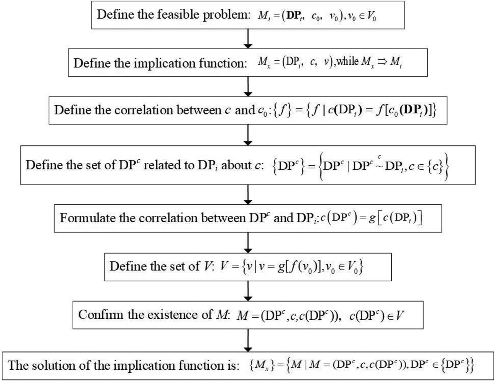
Fig. 4. Solution procedure for implication function.
then the expression of DPi can be obtained as
 $$c( {\rm DP} _i) = g^{{-}1}( c( {\rm DP} ^c) ), $$
 $$c_0( {\rm DP} _i) = f^{{-}1}g^{{-}1}( c( {\rm D}{\rm P}^c) ) \in V_0,$$
which means that the existence of M can lead to the result that the value (v 0) belongs to V 0, that is the realization of Mi.
-
Step 8. The solution of the implication function Mx is represented as a set in Eq. (51).
(51)$${ {M_x} } = { {M\vert M = ( {\rm D}{\rm P}^c, \;c, \;c( {\rm D}{\rm P}^c) ) , \;{\rm D}{\rm P}^c\in { {{\rm D}{\rm P}^c} } } }. $$

Obtaining DP from the fuzzy description of FR is therefore definitive and unambiguous when making use of the approach outlined above. The mapping from FR0 to DP0 is the most important step to generate the whole design scheme and, at the same time, the step is also the most obscured due to lack of information. Applying the feasibility problem-solving process contributes in a significant way to the mapping process by transforming vagueness and imprecision into an unequivocal correspondence described by definitive elements. Once DP0 is determined, one then goes through a process where one zigzags between domains to complete the whole design. As the decomposition process iterates further, the true functional requirement along with the associated design parameter emerges. Consequently, DPi can be obtained by extracting the effective information of the known conditions, omitting the procedure of feasibility problem solving. In response to the issue, a comprehensive Extenics-based method of decomposition is presented in the followings. With affair-elements representing FRs and matter-elements representing DPs, the decomposition process is ordered as follows:
-
Step 1. Extract x independent functions of DPi and build the corresponding matter-element model. Note that, in the early decomposition process, the DPi is in form of concept rather than the concrete structure. Thus, the characteristics besides the function in matter-element are usually uncertain.
-
Step 2. Build the corresponding affair-element model of FRim (m∈(1, x)) according to each independent function of DPi.
-
Step 3. Extract the effective information of the affair-element model of FRim, and determine the corresponding DPim (m∈(1, x)). The feasibility problem-solving method can be applied when applicable.
-
Step 4. Document the design functions generated in the mapping process and make sure they are independent of each other.
-
Step 5. Repeat the above steps till the decomposition of each layer is completed.
The revised iterative decomposition process is summarized in Figure 5.

Fig. 5. Revised iterative decomposition process.
Possibility of expanding solutions from the basic-element expressions
During the decomposition process in AD, designers tend to select a specific solution for each design parameter. This approach can benefit the determination of the design scheme. However, it also restricts the generation of novel design schemes. In this paper, the FRs in form of affair-elements and the DPs in form of matter-elements are abstract concepts instead of concrete structures. What's more, the affair-elements and matter-elements are defined with the definite basic characteristics, which can be used as the objectives for divergence. Divergence analysis is developed from the divergence of the object (O), characteristic (c), and value (v) in a basic-element. According to the principle of divergence in Extenics, one basic-element can be extended to multiple basic-elements with the same object, value, or characteristic.
(1) Divergence of the affair-element model of FR
As discussed in the section “Axiomatic design: a brief overview”, the functional requirement is described in terms of ordered triples in Eq. (26). Dominating object, acting object, and receiving object are the basic components of the verb phrase to describe the functional requirement among the basic characteristics, while the others provide the detailed descriptions with all the aspects of it. The divergence usually happens on u 4~u 8 to achieve different design schemes for the specific FR. For example, Eq. (52) shows a different  ${\rm F}{\rm R}_i^{\prime}$ extended from FRi with the different values $u_7^{\prime}$ and $u_8^{\prime}$. It means that ${\rm F}{\rm R}_i^{\prime}$ has the same function with FRi and the time, location, and degree of the function are also the same. Nevertheless, ${\rm F}{\rm R}_i^{\prime}$ is realized in a different mode and with a different tool.
 $$\left[{\matrix{ {{\rm FR}_i, \;} & {dominating\ object, \;} & {u_1} \cr {} & {acting\ object} & {u_2} \cr {} & {receiving\ object, \;} & {u_3} \cr {} & {time, \;} & {u_4} \cr {} & {location, \;} & {u_5} \cr {} & {degree, \;} & {u_6} \cr {} & {mode, \;} & {u_7} \cr {} & {tool, \;} & {u_8} \cr } } \right]{-}{\rm \vert }\left[{\matrix{ {{\rm F}{{\rm {R}^{\prime}}}_i, \;} & {dominating\ object, \;} & {u_1} \cr {} & {acting\ object} & {u_2} \cr {} & {receiving\ object, \;} & {u_3} \cr {} & {time, \;} & {u_4} \cr {} & {location, \;} & {u_5} \cr {} & {degree, \;} & {u_6} \cr {} & {mode, \;} & {u_7^{\prime} } \cr {} & {tool, \;} & {u_8^{\prime} } } } \right].$$
-
(2) Divergence of the matter-element model of DP
This paper takes the function, principle, structure, arrangement, etc., as the basic characteristics of matter-element [in Eq. (25)]. And each characteristic can be extended to a series of relative attributes. The function of DPi is determined by FRi. When FRi can still be decomposed into several subfunction requirements, it means that the decomposition process has not been finished. In this case, the function of DPi (v 1) can also be decomposed and the other characteristics of DPi are usually vague, denoted as Eq. (53), where “v 11, v 12 …v 1n” represent the subfunction requirements of DPi.
 $$\left[{\matrix{ {{\rm DP}_i, \;} & {\,function, \;} & {v_1} \cr } } \right] - {\rm \vert }\left[{\matrix{ {{\rm DP}_i, \;} & {\,function, \;} & {v_{11} + v_{12} + \cdots + v_{1n}} } } \right].$$
 When the function of DPi cannot be decomposed, the other characteristics can be diverged and then identified. For example, Eq. (54) shows that  ${\rm D}{\rm P}_i^{\prime}$ can achieve the same function of DPi with the different principle, structure, and arrangement. It represents an alternative design scheme.
 $$\left[{\matrix{ {{\rm DP}_i, \;} & {\,function, \;} & {v_1} \cr {} & {\,principle, \;} & {v_2} \cr {} & {structure, \;} & {v_3} \cr {} & {arrangement, \;} & {v_4} \cr {} & \vdots & \vdots \cr } } \right] {-}{\rm \vert }\left[{\matrix{ {{\rm D}{\rm P}_i^{\prime} , \;} & {\,function, \;} & {v_1} \cr {} & {\,principle, \;} & {v_2^{\prime} } \cr {} & {structure, \;} & {v_3^{\prime} } \cr {} & {arrangement, \;} & {v_4^{\prime} } \cr {} & \vdots & \vdots } } \right].$$
As a result, the design space will be broadened owing to the divergence of FR and DP.
The computer-aided system generated based on the improved design procedure
The formalized basic-element models and redefined design process are very suitable for computer processing. The triple form and the relatively uniform characteristics in basic-elements of DP and FR are suitable for design knowledge representation. What's more, the steps in the well-structured design process are explicit and easy to follow. And the divergence of FR and DP can be applied for alternative generating. Based on the articulated concepts and improved design process proposed above, a computer-aided system is established, where the FRs and DPs can be modeled gradually.
Figure 6 shows the interface of the mapping between FRs and DPs, where the FRs and DPs are created and the relationships between FRs and DPs are visualized.

Fig. 6. Interface of the mapping between FRs and DPs.
The FRs and DPs are allowed to be checked, edited, and deleted. One can also create a new FR/DP at the same level, or sub-FR/sub-DP in the system. Moreover, alternatives of one FR or DP are allowed to be created and switched as appropriate.
The FR is created based on the affair-element model discussed above, which is shown in Figure 7. In this interface, the characteristics are allowed to be edited. And each characteristic can be diverged with pressing the button of divergence.

Fig. 7. The creation of FR.
Figure 8 shows the interface of the divergence of a characteristic in FR. The contents in the squares are editable. And the items can be added and deleted with the buttons of plus and minus.

Fig. 8. Divergence of the characteristics in FR.
Similarly, the DP can be created based on the matter-element model and each characteristic of DP can also be diverged (Figures 9 and 10).
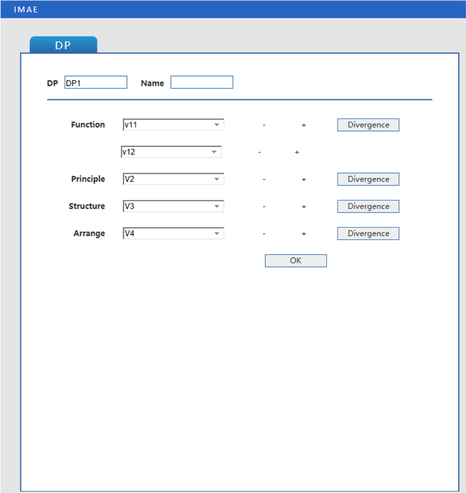
Fig. 9. The creation of DP.

Fig. 10. Divergence of the characteristics in DP.
The computer-aided system helps designers with the design procedure. It's visible and clear what should be taken into consideration at each step with the computer-aided system and the redefined design process discussed above.
When the computer-aided system is used, the FR0 is created firstly in the computer-aided system where the known information is arranged in the interface shown in Figure 7. Then, the designers can establish the feasibility problem model and determine the corresponding DP0 with the solution procedure for implication function (Figure 4). The corresponding DP0 is created in the interface of the mapping between FRs and DPs, as shown in Figure 6. And the detail information of DP0 is edited in the interface of creation of DP, as shown in Figure 9. Then, according to the functions of DP0, the sublayer FRs and DPs can be created gradually.
As discussed in the section “Possibility of expanding solutions from the basic-element expressions”, the FRs and DPs can be diverged to extend the design solutions. In this computer-aided system, the divergence analyses are conducted to each characteristic of FRs and DPs. The users can decide which characteristic to be diverged and how to diverge. Once the alternative solutions are generated according to the divergence, they are stored and can be switched in the mapping interface in Figure 6.
The computer-aided system makes the complex and fuzzy design activity clear and easy to follow by filling in the blanks step by step. The information and knowledge needed are easier to call to mind during the filling process step by step, which is quite helpful to designers especially the nonexperienced ones.
Evaluation about the improved design procedure
As discussed in the section “Introduction”, there is a lack of definitive descriptions for all the elements in the four domains in AD theory, and the approaches essential to guiding the zigzag mapping process are unavailable. Moreover, the design parameters in AD are usually defined as concrete structures, making it difficult to expand the design solutions systematically. These problems are addressed by integrating Extenics with AD theory for the first time in this paper.
In the section “Axiomatic design: a brief overview”, the elements in function domain (FR) and physical domain (DP) are represented with the basic-element models, which have the uniform and specific characteristics in ordered triples for description, making the FRs and DPs as well as the relationship between them clearer compared to the traditional AD theory. Based on that, the vague concept of a FR and a DP in AD can be structured and formalized. The abstract questions about “what the FR/DP is” can be detailed to the concrete questions such as “what the dominating object of the FR is” or “what the principle of the DP is”. The uniform and specific characteristics of the basic-element model play a guidance role to the designers, especially inexperienced designers, in organizing the knowledge and information and constructing the specific representations for the elements in AD design process. The formalized basic-element models can express both specific configurations and conceptual solution with neutral articulation, depending on the value of the characteristics in basic-element. It's another benefit of the basic-element models.
In the section “Extenics: a brief overview”, the design process in AD theory is refined with the Extenics models and methods. In AD theory, it is suggested to solve the design problem in a neutral circumstance, where there shouldn't be any existed design solutions and the thought inertia should be avoided. However, it only proposed the suggestion rather than specific approaches to achieve it. The question as “how to find a proper DP for the FR” is too general and vague that there are no clues and orientation for the designers. To address that, the process of generating DP from a fuzzy FR is defined as the process of solving feasibility problems following Extenics while the zigzag mapping process is also revised considering the information presented in the basic-element model. The vague goal is divided into several concrete steps, and the questions in each step are concretized, making it easier for designers especially inexperienced designers to find clues and inspire design ideas.
In Section “Possibility of expanding solutions from the basic-element expressions”, the divergence of FR and DP makes it possible to expand the design solutions systematically. It makes the inspiration arose by chance can be very likely generated by the divergence analysis of Extenics. Divergence of the characteristics in the basic-element model can help designers achieve the same function with a different principle, structure, or arrangement, that is, a new alternative solution. Up to now, the three problems of traditional AD are all addressed.
What's more, the well-structured design process can be the foundation of a computer design system. The steps in the design process are explicit and easy to follow to develop a design system with computer language. And the divergence of FR and DP can be applied for alternative generating. Moreover, the formalized basic-element models and redefined design process are programmed and a computer-aided system is generated. The triple form and the relatively uniform characteristics in basic-elements of DP and FR are presented in the system, which is quite helpful to the design activity and the extension of design solutions.
In a word, the articulated concepts and improved design process proposed in this paper lay the foundation of intelligent design. Based on that, a computer-aided system is developed. Despite all the achievements, there are still some limits and questions that remain open and can be researched in the future. The computer-aided system is still at an early stage of its development. The construction of the knowledge base, product case database, and more deep computational logic are being planned for the near future. The automation of the computer-aided system still remains to be increased.
It is also worth noting that, the experience and knowledge of designers are also very important and cannot be ignored in a specific design task, just like in all the design methodologies. Nevertheless, the more specific the method steps are, and the more hints and information there are, the more likely for the same designer to obtain good design schemes.
Comparing to AD theory, the proposed design procedure facilitates the generativity since AD does not describe how such mapping is built and leaves it to other existing design theories (such as Hatchuel et al., Reference Hatchuel, Masson, Reich and Weil2011). In the improved design procedure, the generativity of mapping process is enhanced with the well-defined steps.
Furthermore, the generativity of the improved design procedure is realized with “out of the box” principles, comparing to ASIT theory, which insists on “the closed world condition” (Reich et al., Reference Reich, Hatchuel, Shai and Subrahmanian2012). The concept of the basic-element model is somewhat similar to the concept of set theory, based on which the CK theory is proposed. Both of them apply the set that describes certain similar matters. The CK theory is a model for creative design with the concept of two spaces: the knowledge space (K-space) and the concept space (C-space) and the transformation rules between elements in the two spaces (Hatchuel et al., Reference Hatchuel, Masson, Reich and Weil2011; Reich et al., Reference Reich, Hatchuel, Shai and Subrahmanian2012). The proposed improved design procedure is creative in the extension of the set of solutions and functions with the extension features and methods of Extenics.
Application of the improved design method
Corn harvester header is one of the core components that dictates the performance of the harvester with the rate of grain loss and breakage. The energy consumption of the header during the picking process is high. The header of the four-row, self-propelled corn harvester consumes about 17% of the operation energy. Innovative header structure design is commonly explored to seek a better performance in energy efficiency for the corn harvester design. The current design approach renders ambiguity and confusion when searching for design solutions and risking discouraging broad-base thinking that fosters innovation. The knowledge and experience of the designer dominated the process.
The corn plant is shown in Figure 11, and function of the corn harvester is to pick the corn ears from the stalks and then gather the corn ears together (Sun et al., Reference Sun, Zhang, Yang, Gao and Zheng2018) through separating the corn ears form cornstalk at the corn ear stalk.

Fig. 11. The corn plant.
At present, the main corn harvester headers are all with the key component of snapping roller which is used to convey the corn stalks by rolling. A commonly used harvester header is shown in Figure 12 which is produced by John Deere. The corn stalks move toward backward and downward relative to snapping rollers when they enter the gap of two snapping rollers (Wang et al., Reference Wang, Jia, Tang, Zhuang, Jiang and Guo2016). Since the corn ears are too thick to get in the gap, they will be pulled off from the cornstalks.

Fig. 12. A kind of corn harvester header.
An innovative design of the corn harvester header is discussed in this section by applying the improved design methodology elaborated in the previous sections. This is presented as a demonstration of the general applicability of the methodology. Having a definitive rule for guiding the mapping process is particularly critical when one is engaged in the design decomposition layers.
Conceptual design of the corn harvester header
In the followings, a novel corn harvester header is developed. The improved design procedure is followed to generate the design steps outlined below from which an optimal design configuration is emerged.
Step 1. Define the feasibility problem: M 0 = (DP0, c 0, v 0), v 0 ∈ V 0.
It is noted that the “DP0” herein is not for a specific corn harvester configuration. It is a general designation for the feasible design parameters of FR0.
The functional requirement (FR0) of the corn harvester header is harvesting corn ears.
Considering the length limitation of the paper, this example is presented briefly, thus the requirements are set qualitatively rather than quantitatively as shown in Eq. (55), where the FR0 is required to be “with less energy and damage rate”.
 $${\rm FR}_0 = \left[{\matrix{ {{\rm FR}_ 0, \;} & {dominating\ object, \;} & {corn\ ear} \cr {} & {acting\ object} & {{\bf {DP}}_ 0} \cr {} & {receiving\ object, \;} & { whole{\hbox-}plant\ corn} \cr {} & {time, \;} & {u_ 4} \cr {} & {location, \;} & {u_ 5} \cr {} & {degree, \;} & {with\ less\ energy\ and \ damage \ rate} \cr {} & {mode, \;} & {\,pick\,and\,gather\,the\,corns} \cr {} & {tool, \;} & {u_ 8} } } \right],$$
“c 0” is divided into two parts according to Eq. (55): picking corn ears (c 01) and gathering the picked corn ears (c 02). “v 0” represents the degree of c 0, which is, “with less energy and damage rate”. The feasibility problem is represented as Eqs (56)–(58).
 $$M_0 = \left({\matrix{ {{\bf {DP}}_0, \;} & {c_{01}, \;} & {v_{01}} \cr {} & {c_{02}, \;} & {v_{02}} \cr } } \right), \;v_0\in V_0,$$
 $$c_0 = \left({\matrix{ {c_{01}} \cr {c_{02}}} } \right) = \left({\matrix{ {\,picking \ corn \ ears} \cr {gathering \ corn \ ears} } } \right),$$
-
c 01 (DP0) = The function “picking corn ears” of the header.
-
c 02 (DP0) = The function “gathering corn ears” of the header.
(58)$$v_0 = \left({\matrix{ {v_{01}} \cr {v_{02}} } } \right), \quad V_0 = \left({\matrix{ {with\ less\ energy\ and\ damage\ rate} \cr {with\ less\ energy\ and\ damage\ rate} } } \right).$$

Note that the V 0 is the value range determined by FR0, since the degree of FR0 is set qualitatively as “with less energy and damage rate”, the V 0 is also set as a qualitative range. To obtain the feasible DP0 for the given FR0 is to make the value (v 0) belong to V 0, that is, the functions “picking corn ears” as well as “gathering corn ears” of the header should with less energy and damage rate.
-
Step 2. Define the implication function: M x = (DP0, c, v), M x ⇒ M 0, v ∈ V by determining the set of characteristics {c} that are related to c 0. We know that c is related to c 0 and c 0 is determined by c. Herein, the functions in {c 0} are implemented with forces. The corresponding forces are the characteristics related to c 0.
(59)$$c = \left({\matrix{ {c_1} \cr {c_2} } } \right) = \left({\matrix{ {corn \ ears \ picking \ force} \cr {corn \ ears \ gathering \ force} } } \right),$$ -
c 1 (DP0) = Corn ears picking force of the header.
-
c 2 (DP0) = Corn ears gathering force of the header.

According to V 0, corn picking force and corn gathering force should make sure that the corns are harvested with less energy and damage rate. The forces should not be too small to achieve the functions or too great to cause energy waste and high damage rate.
-
Step 3. Set the correlation between c and c 0:
${ f } = { {f\vert c( {{\rm D}{\rm P}_i} ) = f[ {c_0( {{\bf {DP}}_i} ) } ] } }$. Since there are two pairs of c and c 0, there are also two elements in {f}.
(60)$$\eqalign{& { f } = { {\,f_1, \;f_2} }, \cr & c_1( {\rm DP} _0) = f_1[ c_{01}( {\rm DP}_0) ], \cr & c_2( {\rm DP} _0) = f_2[ c_{02}( {\rm D}{\rm P}_0) ]. } $$


The equation “ $c_i( DP _0) {\rm} = f_i[ c_{0i}( {\rm D}{\rm P}_0) ]$” means that “c i(DP 0) is the approach to satisfy c 0i(DP0)”.
-
Step 4. Define the set of corresponding objects DPc related to DP0 about c (c ∈ {c}) as
${ {{\rm DP}^c} } = \left\{{{\rm DP}^c\vert {\rm DP}^c\mathop \sim \limits^c {\rm DP}_0, \;c \in { c } } \right\}$.

Since c is defined in Eq. (59), the DPc is as set of objects that can provide the corn ears picking force and gathering force.
 $${\rm DP}^c_1 = \left\{{\matrix{ {device \ 1{\rm , \;}} & {corn \ ear \ picking \ force, } & {v_1} } } \right\},$$
 $${\rm DP}^c_2 = \left\{{\matrix{ {device \ 2}, & {corn \ ear \ gathering \ force}, & {v_2} } } \right\}.$$
Herein, the v 1 and v 2 are the concrete forms of the forces.
Considering the possibility of expanding solutions from the basic-element expressions (as discussed in Section “Possibility of expanding solutions from the basic-element expressions”), we carry on the divergence of the values according to one characteristic to help the designer broaden the design space.
 $${\rm DP} ^c_1 = \left({\matrix{ {device \ 1 }, & {corn\ ear\ picking\ force}, & {\,pull}, \cr {} & {} & {cut}, \cr {} & {} & {shear}, \cr {} & {} & {break}, } } \right)$$
 $${\rm DP} ^c_2 = \left({\matrix{ {device \ 2}, & {corn\ ear\ gathering\ force}, & {\,push} \cr {} & {} & {lift} \cr {} & {} & {\,fall} } } \right)$$
Herein, four patterns of corn ears picking force and three patterns of corn ears gathering force are established according to expertise. There will be “4 × 3” kinds of solutions accordingly (Table 1).
-
Step 5. Formulate the correlation between DPc and DPi as:
(65)wwhere “g (⋅)” represents the relationship between c(DPc) and c(DPi), that is$$c ( {{\rm DP}^c} ) = g [ {c ( {{\rm DP}_i} ) } ], $$(66)$$\eqalign{& { g } = { {g_1, \;g_2} }, \cr & c _1( {{\rm DP}^c_1 } ) = g _1[ {c_1( {{\rm DP}_0} ) } ], \cr & c _2( {{\rm DP}^c_2 } ) = g _2[ {c_2( {{\rm DP}_0} ) } ]. } $$


The equation “ $c_i( {\rm DP} ^c_i ) = g_i[ c_i( {\rm DP} _0) ]$” means that “ ${\rm DP} ^c_i$ is the specific object of DP0 about ci.
-
Step 6. Define the set of V, which is the value range of DPc.
(67)$$V = { {v\vert v = g[ f( v_0) ] , \;v_0\in V_0} }. $$

Table 1. The solution space of conceptual design

As discussed in Eq. (58), V 0 indicates that the functions “picking corn ears” as well as “gathering corn ears” of the header should with less energy and damage rate. Thus, the picking force should be larger than the fracture stress of the ear stalk but not too large considering the energy-consuming. The gathering force is to collect the corn ears without damaging them, and the energy-consuming should also be considered. As a result, the forces should not be too small to achieve the functions or too great to cause energy waste and high damage rate. Consequently, V can be expressed qualitatively as  $V = \left({\matrix{ {proper} \cr {proper} \cr } } \right)$ for simple.
Accordingly, the solution is selected as
 $${\rm DP} ^c_1 = \left({\matrix{ {device \ 1 }, & {corn \ ear \ picking \ force}, & {break} } } \right),$$
 $${\rm DP} ^c_2 = \left({\matrix{ {device \ 2}, & {corn \ ear \ gathering \ force}, & {\,fall} } } \right).$$
-
Step 7. Confirm the existence of M with the definition
(70)$$M = ( {\rm DP} ^c, \;c, \;c( {\rm DP} ^c) ) c( {\rm DP} ^c) \in V.$$

Obviously, the DPc 1 and DPc 2 shown in Eqs (68) and (69) can be realized technically. And the existence of M can lead to the result that the value (v 0) belongs to V 0, that is the realization of Mi.
-
Step 8. The solution of the implication function Mx is represented as {M x} = {M|M = (DPc, c, c(DPc)), DPc ∈ {DPc}}.
The DPc is processed by merging DPc 1 and DPc 2, as:
 $$ \! {\rm DP}^c = \left\{{\matrix{ \!\! {new{\hbox-}type \ corn \ harvester \ header}, & {corn \ ear \ picking}, & {break} \cr {} & {corn \ ear \ gathering}, & {\,fall} } } \! \right \}.$$
Herein, DPc is a new-type corn harvester header which can break the corns and gather them when they fall. According to implication principle in Extenics, the existence of M will lead to the realization of M 0. Consequently, the DP0 in the physical domain can be found as
 $${\rm DP} _0 = {\rm DP} ^c = \left\{{\matrix{ \matrix{new{\hbox-}type\ corn \hfill \cr harvester\ header, \hfill} & { corn\ ears\ picking, } & {break\ corn\ ears} \cr {} & { corn \ ears \ gathering, } & \matrix{catch\ the\ falling \hfill \cr corn\ ears \hfill} } } \right\}.$$
In this section, 12 kinds of solutions are generated among which the most proper one is selected. It would be very difficult in traditional AD theory to generate the large amount of solutions and obtain the most proper one in once time.
Zigzag-mapping between the function domain and physical domain
A detailed corn harvester header design can be obtained by establishing the zigzagging mapping between the function domain and physical domain using the steps outlined below:
-
Step 1. Extract x independent functions of DP0 and build the corresponding matter-element model.
DP0 is shown in Eq. (72) which is still in form of concept rather than concrete structure. Thus, the characteristics besides the function in matter-element are uncertain.
 $${\rm DP} _0 = \left\{{\matrix{ \matrix{new{\hbox-}type\ corn \hfill \cr harvester\ header, \hfill} & { corn\ ears\ picking\ function} & {break\ corn\ ears} \cr {} & { corn\ ears\ gathering\ function, } & \matrix{catch\ the\ falling \hfill \cr corn\ ears \hfill} } } \right\}.$$
-
Step 2. Build the corresponding affair-element model of FRm (m∈(1, x)) according to each independent function of DP0.
According to the expression in Eq. (73), FR1 is picking corn ears while FR2 is gathering corn ears. The affair-element models of FR1 and FR2 are:
 $${\rm FR}_1 = \left[{\matrix{ {\,pick\ corns, } & {dominating\ object, } & {corn\ ears} \cr {} & {acting\ object}, & {{\rm DP}_1} \cr {} & {receiving\ object, } & { whole{\hbox-}plant\ corns} \cr {} & {time, } & \matrix{when\ ear\ stalk\ arrives \hfill \cr at\ the\ work\ spot \hfill} \cr {} & {location, } & {ear\ stalk} \cr {} & {degree, } & {completely\ detached} \cr {} & {mode, } & {break} \cr {} & {tool, } & {u_8} } } \right],$$
 $${\rm FR}_2 = \left[{\matrix{ {gather\ corns, } & {dominating\ object, } & {corn\ ears} \cr {} & {acting\ object}, & {{\rm DP}_ 2} \cr {} & {receiving\ object, } & { u_ 3} \cr {} & {time, } & \matrix{ after\ the\ corn\ ears \hfill \cr have\ been\ picked\ off \hfill} \cr {} & {location, } & {under\ the\ corn\ ears } \cr {} & {degree, } & {completely\ gathered} \cr {} & {mode, } & \matrix{catch\ the\ falling\ corn \hfill \cr ears\ and\ gather\ them \hfill} \cr {} & {tool, } & {u_ 8} } } \right].$$
-
Step 3. Extract the effective information of the affair-element model of FRim, and determine the corresponding DPim (m∈(1, x)).
When the corn ears reach the work spot of the header, DP1 provides the top-down force on the corn ear. It means that DP1 is a separating unit with the functions of pulling the cornstalk and exerting the force. After the corn ears have been picked off, they will drop down and be caught and gathered by DP2. The corresponding DP2, therefore, is a device for catching and gathering.
 $${\rm DP} _1 = \left({\matrix{ {separating\ unit, } & {\,pull\ the\ cornstalk, } & {to\ find\ the\ ear\ stalk} \cr {} & {exerting\ the\ force, } & \matrix{actual\ stress\ is\ greater \hfill \cr than\ fracture\ stress \hfill} } } \right),$$
 $${\rm DP} _2 = \left({\matrix{ \matrix{device\ for\ catching \hfill \cr and \ gathering, \hfill} & {catch\ the\ corn\ ears, } & {keep\ corns\ from\ dropping} \cr {} & {gather\ the\ corn\ ears, } & {make\ corns\ concentrated} } } \right).$$
-
Step 4. Document the design functions generated in the mapping process and make sure they are independent of each other. As discussed in Eqs (74)–(77), the FR1 and FR2 are totally independent in terms of time. And they are implemented by their own design parameter. When DP1 functions to pick corn ears, it has no effect on the later function FR2. Similarly, when the DP2 functions to gather fallen corn ears, it won't affect the former function FR1. This case is referred to as “independent” according to AD. The design function of this layer can be determined as
(78)$$\left({\matrix{ {{\rm FR }_1} \cr {{\rm FR }_2} \cr } } \right) = \left[{\matrix{ X & 0 \cr 0 & X \cr } } \right]\left({\matrix{ {{\rm DP}_ 1} \cr {{\rm DP}_ 2} \cr } } \right)$$

indicating that the decomposition of this layer results in an uncoupled design.
-
Step 5. Repeat the above steps until the decomposition of each layer is completed. Considering the length of the paper, the similar steps are omitted.
The decomposition process is graphically summarized as follows:
The design parameters in Figure 13 are all described in conceptual matter-element form. The design schemes are not limited to existing components, but are described as conceptual solutions in form of the basic-elements [Eqs (79)–(84)].
 $${\rm DP}_{111} = \left({\matrix{ \matrix{device\ for\ cutting \hfill \cr corn\ stalks \hfill} & {\,function, } & {cutting\ corn\ stalks} \cr {} & {\,principle, } & \matrix{the\ force\ acting\ on\ cornstalk \hfill \cr is \ greater\ than\ fracture\ stress \hfill} \cr {} & {structure, } & \matrix{device\ for\ generating \hfill \cr the\ cutting\ force \hfill} \cr {} & {arrangement, } & {bottom\ of\ the\ header} } } \right),$$
 $${\rm DP}_{112} = \left({\matrix{ \matrix{device\ for\ pulling \hfill \cr corn\ stalks \hfill} & {\,function, } & {\,pulling\ corn\ stalks} \cr {} & {\,principle, } & \matrix{exert\ an\ upward\ force \hfill \cr on\ corn\ stalks \hfill} \cr {} & {structure, } & \matrix{device\ for\ generating \hfill \cr the\ upward\ force \hfill} \cr {} & {arrangement, } & \matrix{above\ the\ device \hfill \cr for\ cutting\ corns \hfill} } } \right),$$
 $${\rm DP}_{12} = \left({\matrix{ \matrix{ device\ for \hfill \cr detaching\ corn\ ears \hfill} & {\,function, } & \matrix{ exert\ force\ to \hfill \cr detach\ corn\ ears \hfill} \cr {} & {\,principle, } & \matrix{the\ force\ acting\ on\ corn\ ear\ is \hfill \cr greater\ than\ fracture\ stress \hfill} \cr {} & {structure, } & \matrix{structure\ for\ generating \hfill \cr the\ detaching\ force \hfill} \cr {} & {arrangement, } & {below\ the\ device\ for\ pulling\ stalks} } } \right),$$
 $${\rm DP}_{13} = \left({\matrix{ \matrix{device\ for \hfill \cr supporting\ cornstalks \hfill} & {\,function, } & {support\ the\ cornstalks} \cr {} & {\,principle, } & \matrix{the\ force\ acting\ on\ cornstalk \hfill \cr prevent\ it\ from\ sagging \hfill} \cr {} & {structure, } & {blocking\ structure} \cr {} & {arrangement, } & {left\ and\ right\ sides\ of\ cornstalks} } } \right),$$
 $${\rm DP}_{21} = \left({\matrix{ \matrix{ device\ for \hfill \cr catching\ corn\ ears \hfill} & {\,function, } & { catch\ the\ falling\ corn\ ears} \cr {} & {\,principle, } & {\,prevent\ the\ corn\ ears\ from\ falling} \cr {} & {structure, } & {blocking\ structure} \cr {} & {arrangement, } & {below\ the\ device\ for\ detaching\ corn\ ears} } } \right),$$
 $${\rm DP}_{22} = \left({\matrix{ \matrix{device\ for \hfill \cr gathering\ corn\ ears \hfill} & {\,function, } & {gather\ the\ corn\ ears} \cr {} & {\,principle, } & \matrix{the\ force\ acting\ on\ corn\ ears \hfill \cr will\ gather\ them\ together \hfill} \cr {} & {structure, } & \matrix{structure\ for\ generating \hfill \cr the\ gathering\ force \hfill} \cr {} & {arrangement, } & {connected\ to\ the\ catchching\ device} } } \right).$$
Fig. 13. The decomposition process of the corn harvester header.
The structures conforming to the features can be used as alternative solutions, expanding the solution space. Thus, the design scheme is not unique. More schemes shall be developed according to the divergence of the basic-element. For example, DP111 can be diverged to multiple types the device for cutting corn stalks.
 $$\left({\matrix{ \matrix{device\ for \hfill \cr cutting \hfill \cr cornstalks, \hfill} & {structure, } & \matrix{ device\ for \hfill \cr generating\ the \hfill \cr cutting\ force \hfill} \cr } } \right){-}{\rm \vert } \left({\matrix{ \matrix{device\ for \hfill \cr cutting\ cornstalks, \hfill} & {structure, } & \matrix{reciprocating \hfill \cr cutting\ device \hfill} \cr {} & {} & \matrix{rotary\ cutting \hfill \cr device \hfill} \cr {} & {} & \vdots } } \right).$$
Each design parameter can be diverged to multiple solutions, then converged to some proper ones. The reasonable solutions are shown in Table 2.
Table 2. Divergence of the structure of each design parameter
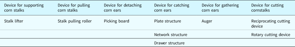
Among the extended design schemes, Figure 14 shows an innovative corn harvester header design emerged as a result.

Fig. 14. Novel corn harvester header design.
Since there are no effects between each pair of FRj and DPi (i≠j), the design function is established to show that the novel corn harvester header configuration is an uncoupled design.
 $$\left({\matrix{ {{\rm FR}_{111}} \cr {{\rm FR}_{112}} \cr {{\rm FR}_{12}} \cr {{\rm FR}_{13}} \cr {{\rm FR}_{21}} \cr {{\rm FR}_{22}} \cr } } \right) = \left[{\matrix{ X & 0 & 0 & 0 & 0 & 0 \cr 0 & X & 0 & 0 & 0 & 0 \cr 0 & 0 & X & 0 & 0 & 0 \cr 0 & 0 & 0 & X & 0 & 0 \cr 0 & 0 & 0 & 0 & X & 0 \cr 0 & 0 & 0 & 0 & 0 & X \cr } } \right]\left({\matrix{ {{\rm DP}_{111}} \cr {{\rm DP}_{112}} \cr {{\rm DP}_{12}} \cr {{\rm DP}_{13}} \cr {{\rm DP}_{21}} \cr {{\rm DP}_{22}} } } \right).$$
As the corn plant reached the front of harvester header, the top of the cornstalk will get into the gap of stalk pulled rollers, while the bottom of the cornstalk will meet the device for cutting corn stalk. Then, the cornstalk is cut off by the device for cutting cornstalk, and it will be lifted by the stalk pulled rollers. During this process, the corn ear is lifted together with the cornstalk. When it arrives at the picking board of the harvester, it will be detached from the cornstalk and fall to the slanting plate, where it will be gathered by the auger.
Concluding remarks
AD and Exenics were reviewed to enable a method to improve the design procedure. This particular insight was pursued to formulate the design procedure that featured mathematical expressions and semantic of logic. The fundamental properties inherent of AD and Exenics were explored to realize the generalized design procedure. The functional requirements and design parameters are expressed mathematically with basic-elements of Exenics. Based on that, the process of generating DP is defined as the process of solving feasibility problems following Extenics and the mapping process of AD was revised. Furthermore, the design solutions can be expanded due to the features of basic-element expressions. A computer-aided system is developed based on the proposed methods for illustrating the relevancy and potential of the design procedure to AI design. In the computer-aided system, the FRs and DPs are created based on the basic-element models. It makes the complex and fuzzy design activity clear and easy to follow by filling in the blanks in a step-by-step manner. The information and knowledge needed are easier to call to mind during the step by step filling process.
Finally, the development of a novel corn harvester header design was elaborated in step-by-step detail to illustrate the implementation of the improved design procedure. The design solution was uncoupled and can be expanded. The three issues in traditional AD are addressed in the article and the improved design procedure appear to be more friendly for inexperienced designer as well as computer to implement. It can supply a better foundation for artificial intelligence design. The methodology is an in-depth synergy of the two theories where the function requirement and design parameters are modeled with the Extenics basic-element. It makes the modeling more explicit with more information compared to other modeling methods. The decomposition process is also improved with well-defined steps, making the decomposition process more coherent. The improved design procedure can be generalized to significantly improve design activity and enable innovation.
Acknowledgments
The authors would like to thank the reviewers for their constructive comments.
Dr. Wenjuan Li received her Ph.D. degree in Vehicle Engineering from China Agricultural University, in 2018. Then, Dr. Li has been in School of Transportation Science and Engineering, Beihang University as a Postdoctor. Dr. Li focuses on the research of Design Methodology. Since 2016, Dr. Li has published 6 peer-reviewed technical papers in international journals and conferences. She is a member of CAAI and served as a reviewer of several SCI journals.
C. Steve Suh is a faculty in the Mechanical Engineering Department at Texas A&M University, and an ASME Fellow. His researches have resulted in exceeding 180 scientific publications, thirteen (13) book volumes and book chapters. He is currently the Editor of Vibration Testing and System Dynamics. He is also serving as an Associate Editor for two internationally renowned archival journals: International Journal of Dynamics and Control and Discontinuity, Nonlinearity, and Complexity.
Xiangyang Xu is currently a professor and a PhD candidate supervisor at School of Transportation Science and Engineering, Beihang University, China. His research interests at vehicle automatic transmission theory and control technology, and presided over the development of the world's first front-drive 8-speed automatic transmission (8AT) and its series products.
Zhenghe Song is a professor of the Engineering College of China Agricultural University. He has long been engaged in the design and experimental research of agricultural machinery and equipment. He has published more than 190 papers and 5 books, and obtained more than 20 authorized invention patents.


