


NOMENCLATURE
- $c_{p,w}$
calorimeter water specific heat capacity, kJ/kg.K
-
$ e_{kin}$
jet specific kinetic energy, MJ/kg
- F
thrust, N
- $ g_{0}$
standard gravity, 9.81, m/s2
-
$ h_{jet}$
jet specific enthalpy, MJ/kg
-
$ I_{sp}$
specific impulse, s
- j
propellant flux, 1/s
- M
molecular mass, kg/mol
-
$ \dot{m}$
propellant mass flow rate, kg/s
-
$ \dot{m}_{w}$
calorimeter water mass flow rate, kg/s
-
$ n_{e}$
electron number density, m–3
-
$ n_{n}$
neutral species number density, m–3
-
$ P_{pl}$
jet calorimetric thermal power, kW
-
$ P_{RF}$
applied coil power, kW
-
$ \dot{Q}_{tube}$
Discharge tube heat flux, kW
-
$ u_{i}$
ionised species velocity, m/s
-
$ u_{n}$
neutral species velocity, m/s
-
$ \dot{V}$
propellant (normal) volumetric flow rate,
$ \textrm{l}_{n}$
/min-
$ X_{s}$
molar fraction of species s


Greek Symbol
-
$ \Delta{T_{w}}$
calorimeter water temperature difference, K
-
$ \Delta{H_{f}}$
dissociation energy, kJ/mol
-
$ \Delta{H_{i}}$
ionisation energy, kJ/mol
-
$ \eta_{F}$
thrust efficiency
-
$ \eta_{th}$
thermal efficiency
-
$ \kappa$
thermal conductivity, kJ/kg.K
-
$ \rho$
density, kg/m3


1.0 INTRODUCTION
For present space missions and operations, Earth represents the sole source of propellant within the solar system. The requirement to launch all necessary propellant with spacecraft from an Earth-based platform hence limits the range and duration achievable for a given mission. However, a number of locations within the solar system present resource-rich environments, with naturally occurring gas species ( $ O_{2}$
,
$ O_{2}$
, $ N_{2}$
,
$ N_{2}$
, $ CO_{2}$
) which may be used as propellants. These locations include asteroids, moons, and other planets such as Mars, each of which have been identified as targets for In-Situ Resource Utilisation (ISRU)(Reference Mazanek, Merrill, Brophy and Mueller1–Reference Sanders3). The ability to utilise resources collected at these sites therefore presents a means to increase the maximum range, duration, and flexibility of space operations.
$ CO_{2}$
) which may be used as propellants. These locations include asteroids, moons, and other planets such as Mars, each of which have been identified as targets for In-Situ Resource Utilisation (ISRU)(Reference Mazanek, Merrill, Brophy and Mueller1–Reference Sanders3). The ability to utilise resources collected at these sites therefore presents a means to increase the maximum range, duration, and flexibility of space operations.
Due to the high exhaust velocity produced by Electric Propulsion (EP) systems, in comparison to chemical propulsion, these systems are able to complete orbital transfers and manoeuvres with a reduced quantity of propellant. Combined with the high costs of conventional EP propellants, namely Xe, the prospect of using these naturally occurring gas species, termed alternative propellants, has motivated a number of numerical and experimental investigations(Reference Frisbee, Polk, Gallimore and Marrsee4–Reference Charles, Boswell, Laine and MacLellan16,Reference Linnell and Gallimore19–Reference Kirtley, Slough, Pihl, Meier and Milroy22) .
This paper presents an overview on previous EP alternative propellant investigations, an assessment of limitations for the respective EP thruster classes, and recent thruster characterization measurements performed for a high-power inductive plasma generator. As will be shown, inductive EP systems are well-suited to the use of alternative propellants and have the potential to significantly influence the choice of propulsion for a given mission.
2.0 PREVIOUS ALTERNATIVE PROPELLANT INVESTIGATIONS
Table 1 lists previous investigations into the use of alternative propellants. These investigations have focused on applications from Atmosphere-Breathing Electric Propulsion (ABEP)(Reference Nishiyama6–Reference Shabshelowitz10) to long-duration cis-lunar trajectories(Reference Frisbee, Polk, Gallimore and Marrsee4), and have considered a variety of conventional and advanced EP systems. Through these studies, the major factors affecting alternative propellant implementation are shown to be chemical compatibility, acceleration mechanism compatibility (relative to the conventional propellant), and scalability of the system.
Table 1 Overview of past studies of alternative propellants for electric propulsion

The first and most fundamental restriction to operation with alternative propellants is that of chemical compatibility. During operation, EP systems are required to maintain nominal performance for periods in excess of 10,000 h(Reference Nishiyama and Kuninaka23,Reference Gonzalez del Amo24) without severe degradation of critical components. Ion thrusters, arcjets, and Magnetoplasmadynamic Thrusters (MPDT) showed significant electrode erosion when operated with chemically reactive alternative propellants(Reference Cifali, Misuri, Rossetti, Andrenucci, Valentian, Feili and Lotz7,Reference Uematsu, Morimoto and Kuriki12–Reference Yanagida, Ohata, Horisawa and Kobayashi15) . Thruster degradation was particularly observable when utilising oxygen, where each of these thruster classes suffered substantial damage to the electrodes over relatively short test times. For alternative propellants to be considered in these systems, significant improvements to the chemical resilience of thruster materials would be required. These improvements may come in the form of additional resistive coatings or a complete reselection of electrode material, though these changes will also heavily impact on the discharge conditions. Hall Effect Thrusters (HET) also showed significant degradation in some cases(Reference Cifali, Misuri, Rossetti, Andrenucci, Valentian, Feili and Lotz7). HET investigations in which no degradation was observed were also recorded(Reference Hohman9,Reference Shabshelowitz10) , though authors of these studies note that testing times were significantly lower than the thruster lifetime and that further testing would provide more substantial indicators of potential damage. Due to the direct contact between electrodes and plasma within these systems, it is likely they will also require significant material modifications. The most compatible systems tested were the helicon thrusters, which displayed no material degradation despite the presence of reactive species, such as oxygen and hydrogen. This compatibility is a result of the helicon thruster’s electrodeless design, which separates the plasma and excitation mechanism (antenna) via a dielectric material.
The second critical issue is the compatibility of the alternative propellant with the thruster accelerations mechanism, which may be electrostatic, electromagnetic, or electrothermal, depending on the thruster. Alternative propellants must also be comparable to their conventional counterparts with respect to the total propulsion system mass and input power requirements. Studies of ion thrusters showed theoretically superior exit velocities with alternative propellants owing to their lower molar mass(Reference Cifali, Misuri, Rossetti, Andrenucci, Valentian, Feili and Lotz7). However, in practice these systems suffered severe reductions in efficiency due to the increase in input power required to ionise the propellant species (in comparison to the conventional propellant, Xe). HET, MPDT, and arcjets showed performance within the same order of magnitude at that achievable using conventional propellants(Reference Cifali, Misuri, Rossetti, Andrenucci, Valentian, Feili and Lotz7,Reference Hohman9,Reference Shabshelowitz10) . However, the aforementioned material limitations act to restrict the potential of such systems. Performance for the helicon sources was mixed. The Helicon Double Layer Thruster (HDLT) achieved specific impulses comparable to electrostatic devices(Reference Charles, Boswell, Laine and MacLellan16), while a conventional helicon source noted negligible improvement over cold gas specific impulse(Reference Shabshelowitz10). This shows that certain helicon sources may require additional acceleration mechanisms to meet the necessary thrust and velocity requirements.
The third major consideration is scalability of the system with respect to power. While the majority of the thrusters tested were small-scale (<2kW), the theoretical mission analyses indicate the need for high-power EP systems to undertake the necessary trajectories and manoeuvres. This is supported by the missions currently being planned, some of which feature EP systems in excess of 10kW(Reference Gonzalez del Amo24,Reference Mercer, Mcguire, Oleson and Barrett25) or 100kW(Reference Mercer, Mcguire, Oleson and Barrett25).
The sum of these considerations hence requires propulsion systems intended for operation with alternative propellants to exhibit high chemical compatibility, a robustness of plasma acceleration with respect to propellant chemical properties, and the ability to be scaled to high input powers. Using these criteria, a suitable candidate for alternative propellant EP is the Inductive Plasma Generator (IPG7) developed at the Institute of Space Systems (IRS)(Reference Herdrich and Petkow26,Reference Massuti-Ballester, Marynowski and Herdrcih27) . This system, originally developed for experimental atmospheric entry simulation, uses an electrodeless mechanism to heat its medium and operates at a maximum power of 180kW. This paper will report on the results of an experimental investigation into thruster performance with a variety of propellants and provide an assessment of how future design iterations may further improve the thrust and specific impulse produced.
3.0 EXPERIMENTAL SETUP
Originally designed for experimental re-entry simulation(Reference Herdrich and Petkow26), the inductive plasma generator systems developed at IRS are compatible with a wide variety of gas species, including highly reactive species such as $ \textrm{O}_{2}$
. IPG7 is the latest iteration of this class of plasma generator, with the experimental facility used for these tests shown in Fig. 1.
$ \textrm{O}_{2}$
. IPG7 is the latest iteration of this class of plasma generator, with the experimental facility used for these tests shown in Fig. 1.
At this facility, the IPG7 is capable of sustained operation at powers up to 180kW for durations in excess of 30 min. Electrical input power is supplied from the source triode to the inductive coil, with a resonant circuit used to minimise reflected power. The supply circuit includes a capacitor bank with seven 6 nF ( $ \pm$
20%) capacitors, used to set the coil driving frequency between 0.5 and 1.5MHz. The number of coil turns can also be used to change the driving frequency(Reference Herdrich and Petkow26,Reference Boehrk28) , though for these experiments a single 5.5 turn coil geometry was used. The number of capacitors was also fixed at 5, resulting in a baseline driving frequency of 586kHz.
$ \pm$
20%) capacitors, used to set the coil driving frequency between 0.5 and 1.5MHz. The number of coil turns can also be used to change the driving frequency(Reference Herdrich and Petkow26,Reference Boehrk28) , though for these experiments a single 5.5 turn coil geometry was used. The number of capacitors was also fixed at 5, resulting in a baseline driving frequency of 586kHz.
The discharge chamber (tube) of the IPG7 is 285mm long, with an outer diameter of 90mm ( $ \pm$
0.2mm) and a tube wall thickness of 2.2mm (
$ \pm$
0.2mm) and a tube wall thickness of 2.2mm ( $ \pm$
0.2mm). The vacuum chamber used within these experiments has a length of 3m and diameter of 2m. This chamber is connected to the IRS main vacuum facility, capable of extracting 150,000m3/h of air at atmospheric conditions and 250,000m3/h at pressures below 10Pa. Without propellant flow, the test facility can be evacuated to ambient pressures of 1Pa. Due to the thruster geometry and high-power nature of the facility, tests using the IPG7 require propellant flow rates of 50–300l
$ \pm$
0.2mm). The vacuum chamber used within these experiments has a length of 3m and diameter of 2m. This chamber is connected to the IRS main vacuum facility, capable of extracting 150,000m3/h of air at atmospheric conditions and 250,000m3/h at pressures below 10Pa. Without propellant flow, the test facility can be evacuated to ambient pressures of 1Pa. Due to the thruster geometry and high-power nature of the facility, tests using the IPG7 require propellant flow rates of 50–300l $ _{n}$
/min (1–6.5g/s), resulting in ambient chamber pressures of 10–30Pa during operation and thruster discharge pressures of 500–2000Pa. While this is a relatively high ambient pressure range for thrust-specific applications, the facility requires such flow rates to match the geometry scale of the thruster. As previously mentioned, the IPG7 was originally designed for re-entry simulation and as such is by no means optimised for thrust generation. The focus of this study is to assess and quantify the behaviour of alternative propellants under fixed conditions, rather than qualify the thruster itself for operation used. As a result, this high ambient pressure is deemed acceptable, with knowledge gained being actively utilised in a separate, thruster development-focused arm of research at IRS(Reference Romano, Herdrich, Binder, Boxberger, Traub, Fasoulas, Schnherr and Roberts29). Potential propellant re-ingestion due to the presence of a measurement probe, thrust or otherwise, was investigated using a Hofer-Noser Karrer (HOKA)(Reference Chadwick, Herdrich, Kim and Dally30) probe. This highly sensitive (
$ _{n}$
/min (1–6.5g/s), resulting in ambient chamber pressures of 10–30Pa during operation and thruster discharge pressures of 500–2000Pa. While this is a relatively high ambient pressure range for thrust-specific applications, the facility requires such flow rates to match the geometry scale of the thruster. As previously mentioned, the IPG7 was originally designed for re-entry simulation and as such is by no means optimised for thrust generation. The focus of this study is to assess and quantify the behaviour of alternative propellants under fixed conditions, rather than qualify the thruster itself for operation used. As a result, this high ambient pressure is deemed acceptable, with knowledge gained being actively utilised in a separate, thruster development-focused arm of research at IRS(Reference Romano, Herdrich, Binder, Boxberger, Traub, Fasoulas, Schnherr and Roberts29). Potential propellant re-ingestion due to the presence of a measurement probe, thrust or otherwise, was investigated using a Hofer-Noser Karrer (HOKA)(Reference Chadwick, Herdrich, Kim and Dally30) probe. This highly sensitive ( $ \pm$
1.5%) device was used to measure the discharge coil current and its interaction with charged heavy particles within the discharge volume. Measurements were first taken under free outflow conditions, with no probes or obstructions between the thruster exit and vacuum facility, and then compared with values recorded during intrusive probe measurements. For the investigation conducted, no significant deviations, within the measurement accuracy of the device, were observed. As such, re-ingestion was deemed negligible. As with the chamber ambient pressure, re-ingestion is of greater interest in assessing the design and development of the thruster itself rather than the propellants utilised. These topics will be investigated in greater detail for subsequent generations of inductive thruster.
$ \pm$
1.5%) device was used to measure the discharge coil current and its interaction with charged heavy particles within the discharge volume. Measurements were first taken under free outflow conditions, with no probes or obstructions between the thruster exit and vacuum facility, and then compared with values recorded during intrusive probe measurements. For the investigation conducted, no significant deviations, within the measurement accuracy of the device, were observed. As such, re-ingestion was deemed negligible. As with the chamber ambient pressure, re-ingestion is of greater interest in assessing the design and development of the thruster itself rather than the propellants utilised. These topics will be investigated in greater detail for subsequent generations of inductive thruster.

Figure 1. IPG7 schematic layout (left)(Reference Chadwick, Herdrich, Kim and Dally30) and during operation with argon (right).
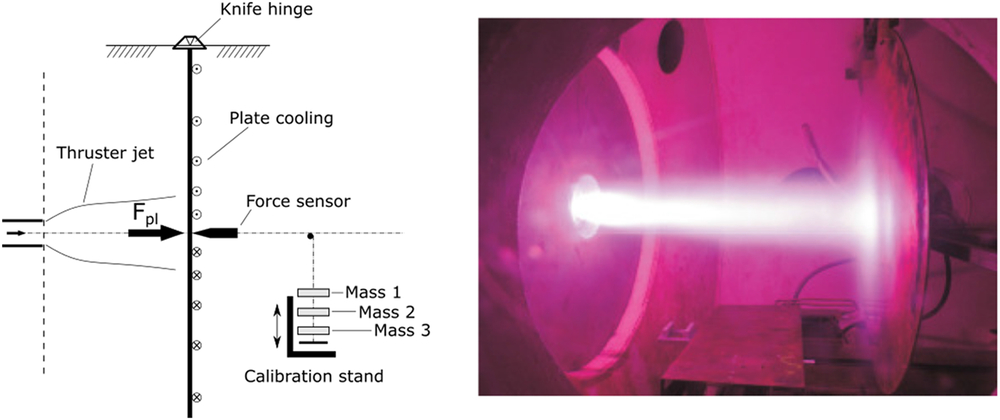
Figure 2. Baffle plate schematic layout (left) and during operation with hydrogen (right)(Reference Boehrk28).
During this investigation, thrust measurements were obtained using a baffle plate arrangement(Reference Boehrk28), shown in Fig. 2. This baffle plate is constructed as a grounded, water-cooled target suspended on knife hinges at a distance of 1.30m from the thruster exit. A ME-Messsysteme KD40s force sensor was used to measure thrust produced by the IPG7 jet, with the diameter of the plate (1.25m) being large enough to capture the full propellant flow. Using a dynamic calibration stand consisting of three distinct masses (0.151, 0.149, and 0.145kg), the force sensor can be calibrated (by means of linear extrapolation) before each test. The major source of errors using the baffle plate result from noise generated by the plate cooling water, used to sustain the high heat loading incident on the copper plate during operation. This results in a measurement error of $ \pm$
0.73 N (< 10%
$ \pm$
0.73 N (< 10% $ \textrm{F}_{max}$
). During cold gas test condition (requiring no water), the baffle plate has been measured to show a
$ \textrm{F}_{max}$
). During cold gas test condition (requiring no water), the baffle plate has been measured to show a $ \pm$
0.27N agreement with a pendulum thrust balance(Reference Boehrk28).
$ \pm$
0.27N agreement with a pendulum thrust balance(Reference Boehrk28).
Using the thrust measurement from the baffle plate, the jet specific impulse ( $ \textrm{I}_{sp}$
) and thrust efficiency (
$ \textrm{I}_{sp}$
) and thrust efficiency ( $ \eta_{F}$
) can be calculated using:
$ \eta_{F}$
) can be calculated using:
 \begin{equation}I_{sp} = \frac{F}{g_{0}\dot{m}}, \end{equation}
 \begin{equation}\eta_{F} = \frac{F^{2}}{2\dot{m}P_{RF}},\end{equation}
where F is the measured thrust, $ g_{0}$
is standard gravity,
$ g_{0}$
is standard gravity, $ \dot{m}$
is the propellant mass flow rate, and
$ \dot{m}$
is the propellant mass flow rate, and $ P_{RF}$
is the input power to the thruster. This value is 75% of the anode power due to inherent triode losses(31), which can be removed with the choice of a more modern power supply.
$ P_{RF}$
is the input power to the thruster. This value is 75% of the anode power due to inherent triode losses(31), which can be removed with the choice of a more modern power supply.
Jet specific enthalpy ( $ \textrm{h}_{jet}$
) was determined using a cavity calorimeter(Reference Herdrich and Petkow26), shown in Fig. 3, and the relation:
$ \textrm{h}_{jet}$
) was determined using a cavity calorimeter(Reference Herdrich and Petkow26), shown in Fig. 3, and the relation:
 \begin{equation}
h_{jet} = \frac{P_{pl}}{\dot{m}} = \frac{c_{p,w}\dot{m}_{w}\Delta T_{w}}{\dot{m}},
\end{equation}
\begin{equation}
h_{jet} = \frac{P_{pl}}{\dot{m}} = \frac{c_{p,w}\dot{m}_{w}\Delta T_{w}}{\dot{m}},
\end{equation}
where $ \textrm{P}_{pl}$
is the thermal power measured by the calorimeter, and
$ \textrm{P}_{pl}$
is the thermal power measured by the calorimeter, and $ \textrm{c}_{p,w}$
,
$ \textrm{c}_{p,w}$
, $ \dot{m}_{w}$
, and
$ \dot{m}_{w}$
, and $ \Delta\textit{T}_{w}$
are the specific heat capacity, mass flow rate, and temperature increment of water flowing through the calorimeter structure. The calorimeter inlet diameter is 125mm, placed 110mm downstream of the thruster outlet in order to capture the full plasma flow and not interfere with the inductive coil by proximity. Once within the calorimeter chamber, thermal energy is extracted from plasma via the water-cooled copper body. The difference in cooling water temperature, combined with the water flow rate, is used to calculate the thermal power of the flow. Values of heat flux within the discharge tube,
$ \Delta\textit{T}_{w}$
are the specific heat capacity, mass flow rate, and temperature increment of water flowing through the calorimeter structure. The calorimeter inlet diameter is 125mm, placed 110mm downstream of the thruster outlet in order to capture the full plasma flow and not interfere with the inductive coil by proximity. Once within the calorimeter chamber, thermal energy is extracted from plasma via the water-cooled copper body. The difference in cooling water temperature, combined with the water flow rate, is used to calculate the thermal power of the flow. Values of heat flux within the discharge tube, $ \dot{Q}_{tube}$
, are determined using the same calorimetric method, using information on the inflow and outflow coolant temperatures as well as the coolant flow rate. In calculating values of
$ \dot{Q}_{tube}$
, are determined using the same calorimetric method, using information on the inflow and outflow coolant temperatures as well as the coolant flow rate. In calculating values of $ \textrm{P}_{pl}$
and
$ \textrm{P}_{pl}$
and $ \dot{Q}_{tube}$
, uncertainties in the cooling water mass flow rate and measured temperature are typically less than 1%. Uncertainties are hence dominated by the stability and duration of the discharge mode at a given input power, which has been explored in previous works(Reference Chadwick, Herdrich, Kim and Dally30).
$ \dot{Q}_{tube}$
, uncertainties in the cooling water mass flow rate and measured temperature are typically less than 1%. Uncertainties are hence dominated by the stability and duration of the discharge mode at a given input power, which has been explored in previous works(Reference Chadwick, Herdrich, Kim and Dally30).

Figure 3. Cavity calorimeter during operation.
Measurements from both the baffle plate and cavity calorimeter were only recorded once steady state, thermal equilibrium conditions had been achieved. Due to the separation of working fluid and excitation mechanism via the dielectric discharge chamber, negligible variation in both thrust and jet power measurements ( $ \approx$
1%) were observed in this facility. Only gradual degradation of the triode anode (over the course of several years of testing) produces significant change in recorded values. This degradation is monitored by facility staff and the anode replaced once inaccuracies exceed a 2% limit. As a result, the primary source of measurement errors in this study were those resulting from cooling water noise, as previously discussed.
$ \approx$
1%) were observed in this facility. Only gradual degradation of the triode anode (over the course of several years of testing) produces significant change in recorded values. This degradation is monitored by facility staff and the anode replaced once inaccuracies exceed a 2% limit. As a result, the primary source of measurement errors in this study were those resulting from cooling water noise, as previously discussed.
For this investigation, four candidate propellants were identified. These are argon, oxygen, nitrogen, and $ \textrm{CO}_{2}$
. Argon was selected due to its similarity to the conventional propellant xenon. Both enter the discharge volume as an atomic gas, reducing the potential energy modes exhibited by the resultant plasma. Oxygen and nitrogen were selected in order to provide two candidate propellants exhibiting a diatomic structure. This allows comparisons to the monatomic argon as well to each other, given their respective dissociation and ionisation energies. These two gases are abundant within the solar system, constituting the primary atmospheric components of several large bodies such as Earth(Reference Barnett and Chandra32) and Titan(Reference Yelle, Strobell, Lellouch and Gautier33). In addition, oxygen may be extracted in significant quantities by processing stores of water found on asteroids and other icy bodies(Reference Liang, Lane, Pappalardo, Allen and Yung34,Reference Shematovich, Johnson, Cooper and Wong35) . Finally,
$ \textrm{CO}_{2}$
. Argon was selected due to its similarity to the conventional propellant xenon. Both enter the discharge volume as an atomic gas, reducing the potential energy modes exhibited by the resultant plasma. Oxygen and nitrogen were selected in order to provide two candidate propellants exhibiting a diatomic structure. This allows comparisons to the monatomic argon as well to each other, given their respective dissociation and ionisation energies. These two gases are abundant within the solar system, constituting the primary atmospheric components of several large bodies such as Earth(Reference Barnett and Chandra32) and Titan(Reference Yelle, Strobell, Lellouch and Gautier33). In addition, oxygen may be extracted in significant quantities by processing stores of water found on asteroids and other icy bodies(Reference Liang, Lane, Pappalardo, Allen and Yung34,Reference Shematovich, Johnson, Cooper and Wong35) . Finally, $ \textrm{CO}_{2}$
was chosen as the polyatomic propellant candidate, allowing knowledge gained from oxygen experiments to be built upon.
$ \textrm{CO}_{2}$
was chosen as the polyatomic propellant candidate, allowing knowledge gained from oxygen experiments to be built upon. $ \textrm{CO}_{2}$
also represents an attractive propellant choice; it is both a significant waste component in spacecraft Environmental Control and Life Support Systems (ECLSS)(Reference Accettura, Bruno, Casotto and Marzari36) and is the primary atmospheric component on Mars(Reference McElroy, Kong and Yung37) and Venus(Reference Hunten, Colin, Donahue and Moroz38).
$ \textrm{CO}_{2}$
also represents an attractive propellant choice; it is both a significant waste component in spacecraft Environmental Control and Life Support Systems (ECLSS)(Reference Accettura, Bruno, Casotto and Marzari36) and is the primary atmospheric component on Mars(Reference McElroy, Kong and Yung37) and Venus(Reference Hunten, Colin, Donahue and Moroz38).
4.0 EXPERIMENTAL RESULTS
Table 2 lists the volumetric mixture ratios, effective mass flow rates, and recorded cold gas thrust values of the propellant conditions investigated. Information on the volumetric flow rate and particle flux of each propellant configuration tested is given in the appendices of this paper. The propellant molar fractions and mass flow rates were varied in order to enable comparisons on volumetric, mass, and particle flux bases.
Table 2 Mixed propellant chemistry (by volume), effective mass flow rate, and cold gas thrust

Figures 4 through 6 show values of thrust, $ \textrm{I}_{sp}$
, and thrust-to-power ratio (
$ \textrm{I}_{sp}$
, and thrust-to-power ratio ( $ \textrm{F/P}_{RF}$
) for pure argon, oxygen, nitrogen, and
$ \textrm{F/P}_{RF}$
) for pure argon, oxygen, nitrogen, and $ \textrm{CO}_{2}$
plasmas, as well as plasmas resulting from combinations of argon and the molecular species.
$ \textrm{CO}_{2}$
plasmas, as well as plasmas resulting from combinations of argon and the molecular species.
As shown in Figs 4 through 6, propellant configurations combining argon and the other gases produced significant increases in measured thrust, $ \textrm{I}_{sp}$
, and
$ \textrm{I}_{sp}$
, and $ \textrm{F/P}_{RF}$
over their pure gas counterparts, with the exception of oxygen which displayed a slight reduction of
$ \textrm{F/P}_{RF}$
over their pure gas counterparts, with the exception of oxygen which displayed a slight reduction of $ \textrm{I}_{sp}$
. The reason for this general increase in thrust-specific performance, as well as the difference between final values obtained by the single propellants, is thought to be a result of the propellant chemical properties and the discharge regime of the resultant plasma.
$ \textrm{I}_{sp}$
. The reason for this general increase in thrust-specific performance, as well as the difference between final values obtained by the single propellants, is thought to be a result of the propellant chemical properties and the discharge regime of the resultant plasma.
At low input powers, heating in the discharge chamber is low due to the low coupling efficiency of the capacitive mode(Reference Herdrich and Petkow26,Reference Chadwick, Herdrich, Kim and Dally30) . As a result, propellants exhibit similar values of $ \textrm{I}_{sp}$
(
$ \textrm{I}_{sp}$
( $ \approx$
50s) at zero input power conditions and similar thrust for input powers below 20kW. At higher input powers, the influence of
$ \approx$
50s) at zero input power conditions and similar thrust for input powers below 20kW. At higher input powers, the influence of $ \textrm{I}_{sp}$
dominates that of the mass flow rate.
$ \textrm{I}_{sp}$
dominates that of the mass flow rate.

Figure 4. Measured alternative propellant thrust at respective mass flow rates (Table 2) and thruster input (RF) power.

Figure 5. Alternative propellant specific impulse (conditions as in Fig. 4).

Figure 6. Alternative propellant thrust-to-power ratio (conditions as in Fig. 4).
The final velocity of particles exiting the thruster is dependent on the species molecular mass. With the exception of $ \textrm{CO}_{2}$
, Ar has the highest molecular mass, with the other propellants able to obtain greater exit velocities in their molecular states. The impact of molecular mass on velocity is further highlighted when considering dissociation of the propellants. Any dissociation of
$ \textrm{CO}_{2}$
, Ar has the highest molecular mass, with the other propellants able to obtain greater exit velocities in their molecular states. The impact of molecular mass on velocity is further highlighted when considering dissociation of the propellants. Any dissociation of $ \textrm{O}_{2}$
,
$ \textrm{O}_{2}$
, $ \textrm{N}_{2}$
, or
$ \textrm{N}_{2}$
, or $ \textrm{CO}_{2}$
greatly increases the maximum obtainable value of
$ \textrm{CO}_{2}$
greatly increases the maximum obtainable value of $ \textrm{I}_{sp}$
in comparison to Ar. In the combined cases, dissociation acts to significantly lower the mean species molecular mass, as shown in Fig. 7.
$ \textrm{I}_{sp}$
in comparison to Ar. In the combined cases, dissociation acts to significantly lower the mean species molecular mass, as shown in Fig. 7.
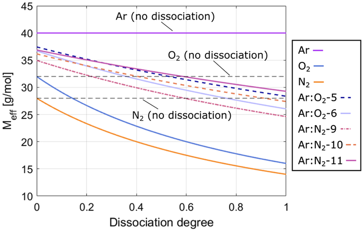
Figure 7. Impact of of propellant dissociation on mean molecular mass.
However, as is seen in Figs 4 through 6, the molecular propellants produced higher thrust when combined with Ar, despite the increase in mean molecular mass. The increase of thrust is also greater than that which can be attributed to the propellant mass flow rate. Thrust values recorded for $ \textrm{N}_{2}$
and
$ \textrm{N}_{2}$
and $ \textrm{CO}_{2}$
were each a factor of 2 higher for 50% and 20% increases in the total mass flow rate, respectively. This improved performance is a result of an increased translational temperature in discharge volume.
$ \textrm{CO}_{2}$
were each a factor of 2 higher for 50% and 20% increases in the total mass flow rate, respectively. This improved performance is a result of an increased translational temperature in discharge volume.
Increasing translational temperature acts to increase the pressure in the discharge chamber and causes propellant to exit the thruster at higher velocities. As the IPG7 is an electrothermal thruster, without additional acceleration mechanisms, the pressure difference between the discharge volume and vacuum tank is the sole source of propellant acceleration. Due to the high discharge pressures and low magnetic field strength of the inductive coil, acceleration from electromagnetic forces can be neglected from analyses of thrust production. Translational temperature in the IPG7 jet is dependent on two primary factors; the quantity of energy transferred from the inductive coil and its distribution among heavy particles in the plasma.
Within electrodeless thrusters, energy is transferred from the coil to the electrons, which in turn transfer energy to heavy particles as a result of collisional (Ohmic) heating. The magnitude of energy conveyed to the propellant is dependent on the electron number density within the discharge volume, requiring consideration of the ionisation energy of the propellant species. Of the propellants tested, Ar yields the highest electron number density per unit of input power. This is due to its atomic structure, with incoming energy converted to either excitation or ionisation processes. By comparison, molecular propellants are subject to additional losses such as dissociation and the rotational and vibrational energy modes. However, despite its affinity for ion and electron production, final $ \textrm{I}_{sp}$
values recorded for Ar were almost a factor of 2 lower than propellant mixtures of significantly higher net ionisation energy. This is thought to be due to the second factor influencing translational temperature in the discharge volume; the thermal conductivity of the plasma.
$ \textrm{I}_{sp}$
values recorded for Ar were almost a factor of 2 lower than propellant mixtures of significantly higher net ionisation energy. This is thought to be due to the second factor influencing translational temperature in the discharge volume; the thermal conductivity of the plasma.
As thrust is produced by heavy particle species (neutral and ionised) in the IPG7, the transfer of energy between atoms and molecules within the discharge volume is of high importance. Observing the thermal conductivities of the propellants investigated (see Appendix), the low value of Ar for both thermal conductivity and specific heat capacity explain why pure Ar propellants were ineffective at converting power from the inductive coil to useful thrust. This conversion was more effective for the molecular species, each of which exhibit higher specific heat capacity and gas thermal conductivity (with the exception of $ \textrm{CO}_{2}$
for which thermal conductivity is lower than Ar at room temperature). A numerical investigation to assess the thermochemical state of the discharge and provide greater insight into these results is presently underway. However, due to the size of undertaking for such an investigation, results cannot be included in this paper.
$ \textrm{CO}_{2}$
for which thermal conductivity is lower than Ar at room temperature). A numerical investigation to assess the thermochemical state of the discharge and provide greater insight into these results is presently underway. However, due to the size of undertaking for such an investigation, results cannot be included in this paper.
The combination of these factors, being the molecular mass of the propellant, the transfer of energy from the inductive coil to electrons, and the distribution of thermal energy in the discharge, can be used to explain the results shown in Figs 4 through 6. $ \textrm{O}_{2}$
displayed the highest final thrust,
$ \textrm{O}_{2}$
displayed the highest final thrust, $ \textrm{I}_{sp}$
, and
$ \textrm{I}_{sp}$
, and $ \textrm{F/P}_{RF}$
from the molecular propellants as a result of its comparably low dissociation and ionisation energies, as well as its high thermal conductivity and specific heat capacity. Both
$ \textrm{F/P}_{RF}$
from the molecular propellants as a result of its comparably low dissociation and ionisation energies, as well as its high thermal conductivity and specific heat capacity. Both $ \textrm{N}_{2}$
and
$ \textrm{N}_{2}$
and $ \textrm{CO}_{2}$
displayed poor performance due to their respective chemical properties. The high ionisation energy, dissociation energy, and specific heat capacity of these two propellants resulted in a high temperature, yet lowly ionised, gas. As a result,
$ \textrm{CO}_{2}$
displayed poor performance due to their respective chemical properties. The high ionisation energy, dissociation energy, and specific heat capacity of these two propellants resulted in a high temperature, yet lowly ionised, gas. As a result, $ \textrm{N}_{2}$
and
$ \textrm{N}_{2}$
and $ \textrm{CO}_{2}$
exerted significant thermal stress on the discharge tube at relatively low input powers (<50kW). This prevented additional power to be applied to the propellant without the risk of critical damage to the thruster. The discharge tube heat fluxes recorded during experiments are shown in Fig. 8.
$ \textrm{CO}_{2}$
exerted significant thermal stress on the discharge tube at relatively low input powers (<50kW). This prevented additional power to be applied to the propellant without the risk of critical damage to the thruster. The discharge tube heat fluxes recorded during experiments are shown in Fig. 8.

Figure 8. Discharge tube heat flux for the alternative propellants (conditions as in Fig. 4).

Figure 9. Capacitive (left), low inductive (centre), and high inductive (right) discharge cross-sections for $ \textrm{O}_{2}$
(Reference Chadwick, Herdrich, Kim and Dally30).
$ \textrm{O}_{2}$
(Reference Chadwick, Herdrich, Kim and Dally30).
The increased thrust, $ \textrm{I}_{sp}$
, and
$ \textrm{I}_{sp}$
, and $ \textrm{F/P}_{RF}$
of the propellant mixtures is a result of preferential combination of propellant chemical properties. By combining argon with the molecular species, argon’s affinity to produce a high discharge electron number density was combined with the high thermal conductivity and low molecular mass of the other gases. This facilitated an effective transfer of energy from the coil to heavy particles in the discharge volume and hence a high thruster performance. Furthermore, the combined thermal conductivity of these propellant mixtures acted to reduce thermal loads on the discharge chamber, allowing
$ \textrm{F/P}_{RF}$
of the propellant mixtures is a result of preferential combination of propellant chemical properties. By combining argon with the molecular species, argon’s affinity to produce a high discharge electron number density was combined with the high thermal conductivity and low molecular mass of the other gases. This facilitated an effective transfer of energy from the coil to heavy particles in the discharge volume and hence a high thruster performance. Furthermore, the combined thermal conductivity of these propellant mixtures acted to reduce thermal loads on the discharge chamber, allowing $ \textrm{N}_{2}$
and
$ \textrm{N}_{2}$
and $ \textrm{CO}_{2}$
to be used with higher input powers.
$ \textrm{CO}_{2}$
to be used with higher input powers.
Table 3 Maximum performance conditions of the propellants tested

Table 4 Comparative performance of other EP systems with alternative propellants

Decreases in discharge tube heat flux for increasing input power, as shown in Fig. 8 for the $ \textrm{O}_{2}$
and Ar:
$ \textrm{O}_{2}$
and Ar: $ \textrm{N}_{2}$
conditions, highlight another critical factor when considering the performance of propellants within the thruster. This behaviour is representative of the high inductive discharge regime, with the plasma condensing about the discharge chamber axis (and hence increasing the thermal boundary layer within the tube)(Reference Herdrich and Petkow26,Reference Chadwick, Herdrich, Kim and Dally30) . Inductively coupled plasma generators display a number of discharge regimes(Reference Herdrich and Petkow26,Reference Lieberman and Lichtenberg44) . These include the capacitive regime and numerous stable (and unstable) inductive regimes, with each regime exhibiting a distinctive electromagnetic field orientation and plasma-coil coupling efficiency. The IPG7 is known to display three distinct stable discharge regimes, being capacitive, low inductive, and high inductive(Reference Chadwick, Herdrich, Kim and Dally30). Examples of the discharge cross-sections of these three regimes are shown in Fig. 9. Energy coupling between the coil and plasma is lowest for the capacitive regime, increases through the low inductive regime, and reaches a maximum in the high inductive regime(Reference Chadwick, Herdrich, Kim and Dally30). Increased coupling efficiency hence leads to a greater proportion of electrical input energy being transferred to the propellant. As can be seen from the results presented in this paper, this has a significant effect on final values of thrust and
$ \textrm{N}_{2}$
conditions, highlight another critical factor when considering the performance of propellants within the thruster. This behaviour is representative of the high inductive discharge regime, with the plasma condensing about the discharge chamber axis (and hence increasing the thermal boundary layer within the tube)(Reference Herdrich and Petkow26,Reference Chadwick, Herdrich, Kim and Dally30) . Inductively coupled plasma generators display a number of discharge regimes(Reference Herdrich and Petkow26,Reference Lieberman and Lichtenberg44) . These include the capacitive regime and numerous stable (and unstable) inductive regimes, with each regime exhibiting a distinctive electromagnetic field orientation and plasma-coil coupling efficiency. The IPG7 is known to display three distinct stable discharge regimes, being capacitive, low inductive, and high inductive(Reference Chadwick, Herdrich, Kim and Dally30). Examples of the discharge cross-sections of these three regimes are shown in Fig. 9. Energy coupling between the coil and plasma is lowest for the capacitive regime, increases through the low inductive regime, and reaches a maximum in the high inductive regime(Reference Chadwick, Herdrich, Kim and Dally30). Increased coupling efficiency hence leads to a greater proportion of electrical input energy being transferred to the propellant. As can be seen from the results presented in this paper, this has a significant effect on final values of thrust and $ \textrm{I}_{sp}$
produced by the thruster.
$ \textrm{I}_{sp}$
produced by the thruster.
4.1 Thruster Comparison with Alternative Propellants
Table 3 shows the maximum thrust and $ \textrm{I}_{sp}$
conditions obtained for
$ \textrm{I}_{sp}$
conditions obtained for $ \textrm{O}_{2}$
,
$ \textrm{O}_{2}$
, $ \textrm{CO}_{2}$
,
$ \textrm{CO}_{2}$
, $ \textrm{N}_{2}$
, and their combinations with argon, including their respective input powers and thrust efficiencies. The performance of conventional EP systems using the same propellants is tabulated in Table 4. As can be seen, values for thrust efficiency and
$ \textrm{N}_{2}$
, and their combinations with argon, including their respective input powers and thrust efficiencies. The performance of conventional EP systems using the same propellants is tabulated in Table 4. As can be seen, values for thrust efficiency and $ \textrm{F/P}_{RF}$
recorded for IPG7 are comparable to the conventional thrusters. However, values for
$ \textrm{F/P}_{RF}$
recorded for IPG7 are comparable to the conventional thrusters. However, values for $ \textrm{I}_{sp}$
are up to a factor of 10 lower than those achievable with ion thrusters. The highest
$ \textrm{I}_{sp}$
are up to a factor of 10 lower than those achievable with ion thrusters. The highest $ \textrm{I}_{sp}$
recorded in this work (236.7 s for
$ \textrm{I}_{sp}$
recorded in this work (236.7 s for $ \textrm{O}_{2}$
) is still well below the 350s value used to justify the use of EP over classical chemical propulsion. However, given the present, basic design of the IPG7, a number of possibilities exist to improve values of
$ \textrm{O}_{2}$
) is still well below the 350s value used to justify the use of EP over classical chemical propulsion. However, given the present, basic design of the IPG7, a number of possibilities exist to improve values of $ \textrm{I}_{sp}$
to a competitive level. Combined with the system’s high thrust and thrust-to-power ratio, the potential for inductive propulsion systems to play a key role in future space operations is high.
$ \textrm{I}_{sp}$
to a competitive level. Combined with the system’s high thrust and thrust-to-power ratio, the potential for inductive propulsion systems to play a key role in future space operations is high.
The primary limitation to propellant exhaust velocity in this system can be described in terms of the suboptimal thruster geometry. While the electrothermal mechanism generates thrust through heating of the working fluid, the constant cross-section of the IPG7 provides no preferential expansion (and hence acceleration) of the gas. This reduces the maximum thruster $ \textrm{I}_{sp}$
in comparison to other electrothermal EP classes such as arcjets, which use a nozzle to accelerate flow from the discharge volume. As a result, the implementation of a mechanical nozzle should provide significant additional jet velocity through dedicated expansion and acceleration of the flow.
$ \textrm{I}_{sp}$
in comparison to other electrothermal EP classes such as arcjets, which use a nozzle to accelerate flow from the discharge volume. As a result, the implementation of a mechanical nozzle should provide significant additional jet velocity through dedicated expansion and acceleration of the flow.
Figure 10 shows values for the jet specific enthalpy, specific kinetic energy ( $ e_{kin} = \frac{1}{2}(F/\dot{m})^{2} - e_{kin,cold}$
), and thermal efficiency (
$ e_{kin} = \frac{1}{2}(F/\dot{m})^{2} - e_{kin,cold}$
), and thermal efficiency ( $ \eta_{th} = P_{pl}/P_{RF}$
) for Ar,
$ \eta_{th} = P_{pl}/P_{RF}$
) for Ar, $ \textrm{O}_{2}$
,
$ \textrm{O}_{2}$
, $ \textrm{CO}_{2}$
, and the Ar:
$ \textrm{CO}_{2}$
, and the Ar: $ \textrm{O}_{2}$
mixtures. With the exception of Ar, the propellants display common trends in jet enthalpy and kinetic energy, tending towards a 25% conversion of enthalpy to usable kinetic energy. The higher ratio for the Ar case is a result of direct transfer of electrical to thermal energy due to the absence of molecular loss mechanisms. The conversion of electrical power to jet thermal power also displays convergence towards a value of 20%. Through the use of a nozzle, the kinetic energy of the flow can be increased. Values of
$ \textrm{O}_{2}$
mixtures. With the exception of Ar, the propellants display common trends in jet enthalpy and kinetic energy, tending towards a 25% conversion of enthalpy to usable kinetic energy. The higher ratio for the Ar case is a result of direct transfer of electrical to thermal energy due to the absence of molecular loss mechanisms. The conversion of electrical power to jet thermal power also displays convergence towards a value of 20%. Through the use of a nozzle, the kinetic energy of the flow can be increased. Values of $ \eta_{th}$
are dependent on the geometry of the discharge volume with respect to the inductive coil, and hence modifications to these values would require more extensive modifications to the thruster design.
$ \eta_{th}$
are dependent on the geometry of the discharge volume with respect to the inductive coil, and hence modifications to these values would require more extensive modifications to the thruster design.

Figure 10. Comparison of jet specific enthalpy, specific kinetic energy, and thruster thermal efficiency for IPG7.
Another method of increasing the specific impulse is to apply an external, electromagnetic or electrostatic acceleration mechanism to the flow, thus increasing the charged heavy particle velocity to levels comparable with other EP systems. However, developed originally as a tool for planetary entry simulation, the primary focus of the IPG7 is to produce flows of high enthalpy rather than a significant degree of ionisation. Previous studies have estimated this degree of ionisation as less than 10%(Reference Sleziona45,Reference Lenzner46) . This limits the impact of charged species on the effective average thruster impulse. Figure 11 shows the effective (mean) specific impulse with respect to flow ionisation degree ( $ n_{e}/(n_{e} + n_{n})$
) for a number of charged particle acceleration gains, calculated as:
$ n_{e}/(n_{e} + n_{n})$
) for a number of charged particle acceleration gains, calculated as:
 \begin{equation}
\skew3\bar{I}_{sp} = \frac{1}{g_{0}}\left(u_{i}\left(\frac{n_{e}}{n_{e} + n_{n}}\right) + u_{n}\left(1 - \frac{n_{e}}{n_{e} + n_{n}}\right)\right),
\end{equation}
\begin{equation}
\skew3\bar{I}_{sp} = \frac{1}{g_{0}}\left(u_{i}\left(\frac{n_{e}}{n_{e} + n_{n}}\right) + u_{n}\left(1 - \frac{n_{e}}{n_{e} + n_{n}}\right)\right),
\end{equation}
where $ u_{i}$
and
$ u_{i}$
and $ u_{n}$
are the ion and neutral exhaust velocities, respectively. The baseline value for
$ u_{n}$
are the ion and neutral exhaust velocities, respectively. The baseline value for $ \textrm{u}_{n}$
is taken from the Ar:
$ \textrm{u}_{n}$
is taken from the Ar: $ \textrm{O}_{2}$
-5 as a reference.
$ \textrm{O}_{2}$
-5 as a reference.
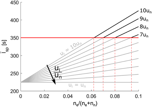
Figure 11. Effective average thruster exhaust velocity after charged particle acceleration.
Accelerating charged heavy species to 10 times the neutral species velocity would provide the necessary mean propellant velocity for $ n_{e}/(n_{e}+n_{n})\gt 6\%$
. While this is a feasible ionisation degree for present IPG7 operation, the flux of propellant through this system is significantly larger than that of present electrostatic or electromagnetic systems. As such, the acceleration mechanism would need to be carefully designed in order to interact with a sufficient proportion of the charged species population. Since a magnetic acceleration mechanism has not yet been developed for such high propellant flows, no comment can presently be made about the amount of additional power required to achieve such performance and its subsequent influence on parameters such as the thrust efficiency. Parallel works at the institute are presently investigating the impact of DC magnets and magnetic novels on smaller-scale versions of the system presented here. The results of these works will be disseminated in future publications.
$ n_{e}/(n_{e}+n_{n})\gt 6\%$
. While this is a feasible ionisation degree for present IPG7 operation, the flux of propellant through this system is significantly larger than that of present electrostatic or electromagnetic systems. As such, the acceleration mechanism would need to be carefully designed in order to interact with a sufficient proportion of the charged species population. Since a magnetic acceleration mechanism has not yet been developed for such high propellant flows, no comment can presently be made about the amount of additional power required to achieve such performance and its subsequent influence on parameters such as the thrust efficiency. Parallel works at the institute are presently investigating the impact of DC magnets and magnetic novels on smaller-scale versions of the system presented here. The results of these works will be disseminated in future publications.
5.0 CONCLUSION
This paper has presented the experimental results of operating a preliminary inductive plasma thruster with alternative propellants. These results indicate that an inductive plasma thruster is compatible with a number of commonly-occurring gases ( $ \textrm{O}_{2}$
,
$ \textrm{O}_{2}$
, $ \textrm{N}_{2}$
,
$ \textrm{N}_{2}$
, $ \textrm{CO}_{2}$
) and that values of thrust and
$ \textrm{CO}_{2}$
) and that values of thrust and $ \textrm{I}_{sp}$
may be significantly increased (up to a factor of 3 in line with the current thruster configuration) by combining the chemical properties of the molecular propellants with an atomic gas, Ar. This combination is thought to take advantage of the low ionisation energy and high thermal conductivity of the monoatomic and polyatomic species, respectively, in order to increase the conversion of energy from the excitation mechanism to the propellant outflow. However, further investigation is needed to better understand the behaviour of the discharge volume. This investigation is presently underway and will be presented in subsequent publications. While the final values of
$ \textrm{I}_{sp}$
may be significantly increased (up to a factor of 3 in line with the current thruster configuration) by combining the chemical properties of the molecular propellants with an atomic gas, Ar. This combination is thought to take advantage of the low ionisation energy and high thermal conductivity of the monoatomic and polyatomic species, respectively, in order to increase the conversion of energy from the excitation mechanism to the propellant outflow. However, further investigation is needed to better understand the behaviour of the discharge volume. This investigation is presently underway and will be presented in subsequent publications. While the final values of $ \textrm{I}_{sp}$
presented in this paper are significantly lower than those achievable with conventional EP system, the lack of material degradation associated with inductive propulsion (when compared to direct-contact electrode systems) presents a distinct advantage. Furthermore, the geometry of the IPG7 may be further improved to increase the propellant acceleration. Modifications include the addition of a mechanical or magnetic nozzle or alterations to the discharge chamber geometry (to increase the maximum thermal efficiency of the system). Inductive propulsion systems hence have the potential to facilitate longer-duration, flexible-space operations without the reliance on Earth as the sole source of propellant in the solar system.
$ \textrm{I}_{sp}$
presented in this paper are significantly lower than those achievable with conventional EP system, the lack of material degradation associated with inductive propulsion (when compared to direct-contact electrode systems) presents a distinct advantage. Furthermore, the geometry of the IPG7 may be further improved to increase the propellant acceleration. Modifications include the addition of a mechanical or magnetic nozzle or alterations to the discharge chamber geometry (to increase the maximum thermal efficiency of the system). Inductive propulsion systems hence have the potential to facilitate longer-duration, flexible-space operations without the reliance on Earth as the sole source of propellant in the solar system.
ACKNOWLEDGEMENTS
The authors of this paper would like to thank the Sir Ross and Sir Keith Smith Foundation and the German Research Foundation (DFG, Project HE 4563/3-1) for their financial contributions to personnel and equipment during this project.
APPENDIX
Table 5 Chemical properties and reaction data for the species considered in this work(Reference Linstrom and Mallard39,Reference Cottrell40,Reference Darwent41,Reference Benson42,Reference Kerr43)

Table 6 Propellant flow rates tested


