


1.0 INTRODUCTION
Aviation meteorology has been an important area in the aeronautical research field since the time of the first flight by the Wright brothers(Reference Dines1). Meteorological conditions, such as gust(Reference Etkin2), icing(Reference Cao, Wu, Su and Xu3), heavy rain(Reference Cao, Wu and Xu4), etc., have been well known to have catastrophic influence on aviation safety. Of these weather conditions, atmospheric gust or turbulence is a most common one encountered by aircraft. The adverse influences of gust or turbulence on aviation have been taken into account to even before man’s first flight(Reference Hunsaker and Wilson5,Reference Wilson6) . Concerns about aircraft gust disturbance have increased not only because of the design cases that are not primarily structural but also because of gust influence on aircraft handling qualities and flight controllability.
Over the past century, substantial literature has been published, including reviews and research reports at different stages of the growing understanding of the subject. The earliest review on gust loads on aircraft might be the one written by Zbrozek(Reference Zbrożek7) in 1965. In his review, the influence of atmospheric turbulence on some aspects of aircraft engineering was mentioned, and the problem of the calculation was discussed in some detail. In 1970, Burnham(Reference Burnham8) wrote a review introducing the latest research progress that the Royal Aircraft Establishment (RAE) had made on gusts at that time. Several years later, Houbolt(Reference Houbolt9) published a review paper elaborating the influence of atmospheric turbulence, mainly related to gusts, on the flight and design of aircraft. In 1992, Wyngaard(Reference Wyngaard10) reviewed atmospheric turbulence from a meteorological point of view, which more or less involved the issue of gust. In 2006, Etele(Reference Etele11) wrote a concise review of wind gust modeling and application to autonomous low-level Unmanned Aerial Vehicle (UAV) control. However, a comprehensive review on the effects of gust loads on aircraft has been lacking during the past decades. However, as the worldwide industrial manufacturing capability has experienced enormous development, many new experimental techniques have emerged in studying gust effects on aircraft, e.g., gust wind tunnel. Moreover, with the computer technology advancing fast over the past decades, a new research approach termed CFD (Computational Fluid Dynamics) numerical simulation is emerging and has obtained significant research achievement that traditional experimental methods can hardly reach.
This paper presents an overview of the present and future state-of-the-art research taking into account of gust loading on aircraft. The whole text begins with an introduction of the gust research background and significance in the first section. The second section describes some concepts and mathematical descriptions of various gusts. The third section introduces the existing techniques and theories of gust research. The fourth section, as the most important one, analyzes the influences of gust disturbances on aircraft aerodynamic performance, structural and flight dynamics. The fifth section presents the state-of-the-art gust alleviation measures from both the academic and industrial application perspectives. Finally, a summary of the present research progress on aircraft gust disturbances as well as an outlook to the future research is presented. It should be noted that, although this review has attempted to assimilate all the major aspects to give a synthetic understanding of gust loads on aircraft as far as possible, still a complete understanding of the effects and alleviations of gust disturbances on aircraft requires additional significant efforts in both experimental and analytical ways. After that, assessment of the degree of hazard to aircraft flight safety in a gust encounter is possible.
2.0 DESCRIPTION OF GUST
Modeling of gust loads has been the subject of technical interest since the very first NACA publication in 1915(Reference Hunsaker and Wilson5). The models have evolved for design and certification of gust loads over the years, which are placed in the following categories: discrete gust model for static loads, discrete gust model for dynamic loads, continuous gust model and statistical discrete gust (SDG) model. A brief description is provided for each category in this section. To be concrete, at least dozens of subclasses of gust load models have been developed, both for civil and military applications(Reference Heffley, Jewell, Hoh and Moorhouse12). Due to the vast quantity of the models, herein only an extension is made from the broad aspect of the original models that are being adopted by the current design and certification regulations.
2.1 Terminology
2.1.1 Directionality
In terms of the directionality of gust, there are three kinds of gust, i.e., vertical, lateral and head-on gusts. The effects of each kind of gust are ordinarily considered equal to change the angle of attack, side-slip angle and dynamic pressure of the aircraft, respectively. This is due to the individual directional components of gust velocity at orthogonal angles to the flight path, as shown in Fig. 1, where V is the aircraft forward flight speed, U is the gust velocity, and Ve is the aircraft effective velocity.
Figure 1. Illustration of gust directionality.
2.1.2 Alleviation factor
The gust alleviation factor, K, is defined as the relative response of two airplanes encountering the same gust. The alleviation factor has different definitions in the long history of gust load. It was first chosen for response estimation in the earliest time, due to the complexity of the problem in determining aircraft response to gusts and the difficulties in sampling gust load data for all aircrafts. In 1949, Donely first used the B-247 airplane as a reference, assuming that all aircraft of that time period had the general response characteristics of the B-247. The reason is that the Boeing B-247 transport airplane was an experimental measurement airplane that had collected a vast amount of gust-related data for many years(Reference Walker and Hadlock13). The gust velocities were defined as “effective” gust velocities as determined from the response of the B-247 aircraft using the simple sharp-edge gust formula with no alleviation factor. An alleviation factor K was then defined as the response of another aircraft relative to that of the B-247. It is a function of the wing loading,  ${W \over S}$, expressed as
 $$K\left\{ {\matrix{{{1 \over 2}\left( {{W \over S}} \right)^{1/4} } & {\left( {{W \over S} \le 16} \right)} \cr {1.333 - {{2.667} \over {\left( {{W \over S}} \right)^{3/4} }}} & {\left( {{W \over S}} \right) \ge 16} \cr } } \right.$$
where W is the weight of aircraft and S is the reference wing area.
By the early 1950s, the need to take structural dynamic response into account became evident, and the US air authorities ANC (Air Force, Navy and Civil (FAR, Federal Air Regulation)) required to define a more rational discrete gust for rigid-body and structural dynamic analyses. Donely was then asked to evaluate the airplane response to the one-minuscosine gust shape. According to his research results, a new definition of gust alleviation factor K g was developed as a function of the mass ratio μ g, which is approximated as(Reference Pratt14)
 $$K_g = {{0.88\mu _g } \over {5.3 + \mu _g }}$$
for subsonic aircraft, where
 $$\mu _g = {{2W/S} \over {a\rho gc}}$$
where a is the slope of lift curve per radian, ρ is the air density, g is the gravitational acceleration and c is the mean geometric wing chord. This value of gust alleviation factor is still being adopted by the main airworthiness regulations like the CS-25 of European Aviation Safety Agency(Reference Easa15).
2.1.3 Load factor
Gust load factor, n, is defined as ratio of the lift of an aircraft penetrated in a gust to the aircraft weight. It represents the aircraft normal overload or acceleration encountering a gust and can be expressed as
 $$n = {L \over W} = 1 \pm \Delta n$$
where L is the aircraft lift under a specific gust load, W is the aircraft weight, Δn is the acceleration increment due to gust and for most cases, Δn = n − 1. The maximum value of Δn is termed as the gust load formula and will be involved in the next subsection.
2.1.4 Power spectral density
Power spectral density (PSD) is a parameter reflecting average variation of energy with frequency or wavelength. In the expression of PSD, “power” denotes that the quantity to which the various frequency components contribute is the mean square value of the variable, “spectral” indicates a measure of frequency content and “density” implies that the frequency components are continuously distributed rather than discrete. Therefore, one can only speak of the contribution of a band of frequencies between ω and ω + dω, as shown in Fig. 2.
Figure 2. PSD as a function of the radian frequency.
The PSD function is normally represented as a function of the radian frequency ω by Φ(ω). If Φ(ω) is the PSD of the quantity y (t), then the square root of y (t), σ y, which is the area of the area under the PSD curve as shown in Fig. 2, can be derived by
 $$\sigma _y = \sqrt {\int_0^\infty \Phi (\omega )d\omega }$$
2.2 Discrete gusts for static loads
This subsection introduces three commonly used discrete gust models for static loads calculations, i.e., sharp-edge gust, linear-ramp gust and one-minus-cosine gust. It is noted that there are many other types such as sinusoidal and graded gust models(Reference Wu, Wang and Huang16), which nowadays are only for research applications while not required in the world’s main airworthiness regulations.
2.2.1 Sharp-edge gust
The concept of sharp-edge gust was reported in 1931(Reference Rhode and Lundquist17). This simplest gust shape proposed by albeit a century ago, is still used for response analysis to date. The gust shape is of a step type, as shown in Fig. 3. The gust velocity profile can be expressed by Equation (6).

Figure 3. Illustration of sharp-edge gust velocity distribution.
 $${{u(s)} \over U} = 1$$
where U is the gust maximum velocity value, u(s) is the gust velocity at any penetration distance, s.
The U.S. Bureau of Air Commerce regulated the first U.S. civil requirements related to gust loads in the “Airworthiness Requirements for Aircraft Components and Accessories” issued in 1933(18). These requirements were merely based on the sharp-edge gust concept. The design gust velocity is 30 fps for aircraft at cruise speeds and 15 fps at dive speeds.
2.2.2 Linear-ramp gust
The linear-ramp gust concept had become apparent by the late 1930s. This concept was used to account for the differences in airplane motion due to gust encounter from one airplane to another. The linear-ramp gust shape means the gust velocity increases linearly with the gust gradient distance, as shown in Fig. 4. The gust velocity profile can be expressed by Equation (7),

Figure 4. Illustration of linear-ramp gust velocity distribution.
 $$\left\{ {\matrix{{{{u(s)} \over U} = {s \over H}\;\;\;\;\;\;\;\;\;\left( {0 < s < H} \right)} \hfill \cr {{{u(s)} \over U} = 0\;\;\;\;\;\;\;\left( {s < 0\;{\rm{or}}\;s > H} \right)} \hfill \cr } } \right.$$
where, H is the gust gradient distance (horizontal distance from zero to maximum gust velocity, usually in wing chord length).
The regulations that resulted were contained in the 1941 issue of the Civil Aeronautics Manual (CAM 04)(19), where the equivalent gust velocity was specified as 40, 30 and 15 fps for three different forward air speeds.
2.2.3 One-minus-cosine gust
The current certification regulations utilise theoretical work undertaken by the NACA where the concept of one-minus-cosine gust was reported in 1953(Reference Pratt14). The gust shape is shown in Fig. 5 and is mathematically defined as
Figure 5. Illustration of one-minus-cosine gust velocity distribution.
 $$\left\{ {\matrix{{{{u(s)} \over U} = {1 \over 2}\left( {1 - \cos {{\pi s} \over H}} \right) = \mathop {\sin }\nolimits^2 {{\pi s} \over {2H}}\;\;\;\;\;\;\;\left( {0 < s < 2H} \right)} \hfill \cr {{{u(s)} \over U} = 0\;\;\;\;\;\;\;\;\;\;\;\;\;\;\;\;\;\;\;\;\;\;\;\;\;\;\;\;\;\;\;\;\;\;\;\;\;\;\;\;\left( {s < 0\;{\rm{or}}\;s > 2H} \right)} \hfill \cr } } \right.$$
where the symbols are identical to those for sharp-edge gust. In the whole history, the gust gradient distance H was designated to different values successively, such as 12.5 and 25 chords; however, the latest regulations of the gust gradient distance in FAR-25(20), CS-25(Reference Easa15) and JAR 25(21) require a sufficient number of gust gradient distance in the range of 30 feet to 350 feet to be investigated in order to find the critical response for each load quantity.
2.3 Discrete gusts for dynamic loads
In the history, there had been a time when the need of the determination of discrete gust dynamic loads existed(Reference Hoblit22), although now it is thoroughly superseded by the continuous turbulence loads requirements of FAR(20) and EASA(Reference Easa15). The term ‘dynamic loads’ is used to represent gust loads that include the inertia forces associated with elastic-mode (free-vibration) accelerations. In the calculation of static gust loads, the gradient distance seems to be arbitrarily chosen. This does not mean that all actual gusts are of the same gradient distance,but the actual gust gradient distance, from a static gust load point of view, is not very important. However, the dynamic response is indeed sensitive to the gradient distance(Reference Hoblit22).
Ingredients of the discrete gust dynamic loads differential equations include the generalised elastic and ridged-body modes of coordinates, the aerodynamics and coupling of the various modes, time-history solutions of the differential equations and the integrated loads computed from the time histories of the gust inputs. It includes the motions in the various rigid-body and elastic modes as well.
2.4 Continuous gusts
Gust profiles in the atmosphere typically tend to be continuous and random. Continuous gust load models allow a statistical representation of gusts in the atmosphere to account for all gust frequencies. The continuous gust concept is based on the assumption that atmospheric turbulence can be described as a stationary Gaussian process and the airplane be considered as a linear system. The profile or time history is idealised as stationary, because it is considered to be of infinite duration and its statistical properties are the same wherever it may be sampled. The profile is also Gaussian because if the time history is sampled at many random and equally spaced points, the resulting probability distribution is Gaussian, often called ‘normal.’ Two basic reasons are for the stationary Gaussian idealisation of continuous gusts. First, it is much more realistic than the simple discrete-gust idealisations. It provides inherently:
(1) The infinite variation in the shape of individual gusts;
(2) The variation of gust magnitude with gradient distance;
(3) The proper superposition of very short-gradient gusts that excite the various elastic modes with the longer-gradient gusts that give the largest rigid airplane loads;
(4) The reduced gust velocity properly associated (on an equal-probability basis) with a resonant series of gusts.
Second, this idealisation makes it easier to associate continuous gust load models in various mathematical expressions of aerodynamics and aeroelastics. Techniques called isegeneralised harmonic or power-spectral analyses allow the derivation of aircraft dynamic responses (accelerations, loads, etc.) by using the statistical representation of continuous gust velocity profiles. In terms of realism, the quasi-stationary Gaussian idealisation is simpler to apply than any other discrete-gust idealisation.
Based on these assumptions, the PSD method for the derivation of airplane design and fatigue loads has been developed. From the design point of view, two shapes of gust velocity PSD have been widely used, the von Kármán spectrum and the Dryden spectrum. The von Kármán model is the preferred model of continuous gusts for the FAA(20) and the EASA(Reference Easa15), which first appeared in the 1957 NACA report(Reference Diederich and Drischler23) based on earlier work by Theodore von Kármán(Reference De Karman and Howarth24–Reference Von Kármán and Lin26). The Dryden model is one of the most commonly used models of continuous gusts, which was first published in 1952(Reference Liepmann27).
von Kármán:
 $$\Phi _g (\omega ) = \sigma ^2 {{L_g } \over \pi }{{1 + {8 \over 3}(1.339L_g {\omega \over V})^2 } \over {\left[ {1 + (1.339L_g {\omega \over V})^2 } \right]^{11/6} }}$$
Dryden:
 $$\Phi _g (\omega ) = \sigma ^2 {{L_g } \over \pi }{{1 + 3L_g^2 ({\omega \over V})^2 } \over {\left[ {1 + L_g^2 ({\omega \over V})^2 } \right]^2 }}$$
where Φg is power-spectral density, σ is root-mean-square gust velocity, ω is the frequency L g is called scale of gust and is specified at 2500 ft.
The above two PSD models are capable of modeling vertical and lateral gusts, which is the usual application. However, for longitudinal gusts, the corresponding equations, albeit seldom applied, are:
von Kármán:
 $$\Phi _g (\omega ) = \sigma ^2 {{2L_g } \over \pi }{1 \over {\left[ {1 + (1.339L_g {\omega \over V})^2 } \right]^{5/6} }}$$
Dryden:
 $$\Phi _g (\omega ) = \sigma ^2 {{2L_g } \over \pi }{1 \over {\left[ {1 + (L_g {\omega \over V})^2 } \right]^2 }}$$
In developing a gust load criterion based on power-spectral analysis that can be used without referring to any specific comparison airplane, three approaches were proposed by Hoblit, et al. in 1966(Reference Hoblit, Paul, Shelton and Ashford28). The first is the mission analysis criterion. This type of criterion requires establishment of typical mission profiles and then break them down into segments. Certain minimum requirements may properly be specified to account for the more severe elements of the operational spectrum. The second is the design envelope criterion. It leads to a criterion where we need to design a specified design envelope of speed, altitude, gross weight, fuel weight and centre of gravity position. The third criterion, a combination of the former two criteria, is suggested(Reference Hoblit22). By means of a realistic mission analysis it can be assured that the gust loads defined provide a safe strength level, but this level is not overly conservative. Substantial considerations need to be taken to include various atypical flight conditions, e.g., extremes of centre of gravity position, payload, speed, altitude, etc. A combined criterion could retain the advantages of the mission analysis criterion. The combination of both the mission analysis and design envelope criteria is adopted in the FAR-25 continuous gust design criteria.
It is noted that both of the von Kármán and Dryden gust models have been widely used by gust researchers and have been integrated in some commercial application software(29,30) . However, the mainstream airworthiness regulations(Reference Easa15,20) employ the von Kármán model for gust design purpose, because it gives better fit to observed data and is supported by theory at higher frequencies. On the other hand, although the continuous gust load approach offers a more robust and realistic representation of the atmosphere, yet it has not superseded the discrete-gust approach in the practical design and certification. Flight data recorders have indicated that larger gusts often exist as discrete ones(Reference Fuller31) and the discrete gust approach is more suitable for predicting discrete gust load effects. For these reasons, both the discrete gust and continuous gust load models are presently required by FAR-25 certification(Reference Easa15,32) , as well as others.
2.5 Statistical discrete gusts
Although the continuous gust model is more appropriate to describe the real gust profiles, yet the widely used PSD theory fails to take adequate account of the strong statistical correlations that exist between the phases of Fourier components in turbulence velocity. The PSD approach carries no phase information. Instead, it introduces the additional assumption that phases are purely random and hence local patches of turbulence can be represented as samples of a Gaussian process.
Recently, the statistical discrete gust (SDG) model was proposed(Reference Jones33–Reference Jones, Watson and Foster38) as a means of modeling non-Gaussian characteristics of inertial-range turbulence and the associated effects on aircraft response, which was adopted by the British airworthiness regulations. In this model, the variation of U with H is related explicitly to probability. Generally, there seems a consensus that gusts of shorter gradient distance tend to have lower gust velocity. Jones proposed a relationship between maximum gust velocity U and gradient distance H, as written below(Reference Jones36):
 $$U \propto H^{1/3} $$
In the basic model proposed by Jones, the gust is like the first half of the one-minus-cosine form, as shown in Fig. 6, and the frequency of gust encounter is given by
Figure 6. Family of gust velocity as a function of gradient distance(Reference Jones39).
 $$N\left( {U,H} \right) = {\alpha \over {H^2 }}\exp \left( { - {U \over {1.15\beta H^{1/3} }}} \right)$$
where N (U, H) is the number of discrete gusts per unit gradient distance. α and β are frequency and amplitude parameters respectively that fix the family of gusts of our interest. The exponential form of gust frequency of occurrence is a realistic non-Gaussian probability distribution for different gust velocities.
This model evaluates aircraft response to gust based on a worst-case approach. At any given probability level, one can choose the worst gust from an almost equiprobable family containing various U and H, see Fig. 6. Such a single ramp gust is enough to obtain the response of a heavily damped airplane mode. For lightly damped modes, a succession of gusts properly spaced is required to build up the resonance. The maximum response corresponds to a tuned gust of the right H in the British airworthiness regulations.
3.0 RESEARCH METHODOLOGY
Assuming a gust encounter, modeling of gusts plays a critical role in the design phase of an aircraft. Many approaches have been developed to analyse gust loads, primarily classified into three categories, i.e., analytical modeling, experimental measurement and CFD (Computational Fluid Dynamics) numerical simulation.
3.1 Experimental measurement
In an attempt to collect data for mathematical modeling of gust, to develop improved approaches to calculate aircraft dynamic responses to gust loads and to better understand the nature of atmospheric gusts, many measuring methods have been exploited. The following sections explain briefly the existing gust measuring methods.
3.1.1 Real flight
The treatment of gust loads on a statistical basis was undertaken in the 1930s by collecting statistical data of gust loads experienced by commercial aircraft. The data was collected using the NACA (National Advisory Committee of Aeronautics, now renamed as the ‘National Aeronautics and Space Administration’, i.e., NASA) V-G recorders(Reference Rhode40), which used a stylus scratching on a smoked glass, driven by an airspeed sensor in the horizontal direction and an accelerometer in the vertical direction. After many hours of flight, the centre portion of the glass was wiped clean, leaving only the extreme values clearly visible. This enabled a statistical description of the largest gust loads and airspeeds encountered as a function of a long flight time. In the practical flights, the airplanes were operated at an average pressure altitude of 6,500ft with each individual flight of approximately 200 miles or 1hr. The data collected by the V-G recorders were the maximum positive and negative normal acceleration increment in g units Δn max, the corresponding indicated airspeed V 0. The maximum effective gust velocity Ue max given in the sharp-edge-gust formula was computed by(Reference Steiner41)
 $$Ue_{\max } = {{2\Delta n_{\max } W/S} \over {1.47\rho aKV_0 }}$$
where the other symbols can be referred to in Sec. 2.1.2. Herein the alleviation factor K was calculated on the basis that the gust shape is of a ramp type defined above.
Later, the gust velocity was later revised by substituting the gust alleviation factor K g defined in the above Equation (2), which forms(Reference Pratt and Walker42)
 $$Ue_{\max } = {{2\Delta n_{\max } W/S} \over {1.47\rho aK_g V_0 }}$$
where the gust factor K g is calculated on the basis of a one-minus-cosine gust shape and is presented as a function of both mass-ratio and wing loading. This modification provides a more appropriate and acceptable basis for gust-load calculations between the majority of the regulating agencies. During the period from 1933 to 1950, a considerable amount of data was collected by Walker on V-G recorders from operations of large transport airplanes in large gusts(Reference Pratt and Walker42). The V-G data was supplemented later with oscillographic records that provided data on the higher frequency of occurrence of small gusts.
Two approaches have been utilised for flight investigations of airplane reactions. One consists simply of detailed analysis of flight records to obtain the desired relations, for example, between the pitch of an airplane and the acceleration imposed on the airplane. The other one consists of flying an airplane in rough air to obtain statistical data for different conditions and then statistically comparing the reactions of the airplane. The statistical approach may permit checks to be made of both theoretical and gust tunnel results, but the procedures and techniques have not been developed to the point where precise results can be obtained.
3.1.2 Fixed track
Considering that the real flight method is associated with high cost and risk, an alternative technique called fixed track was developed by NACA(Reference Donely43). This technique was also applied by some successors e.g., Beauvais(Reference Beauvais44), Kobayakawa and Maeda(Reference Kobayakawa and Maedat45) and Howell(Reference Howell46). The substance of this method is schematically illustrated in Fig. 7. A launcher, such as a carriage or a truck, whose kinetic energy is attained from a coil spring or other forms of energy-storage systems, carries the model aircraft along a given track to be penetrated in the gust effected by the downstream gust generator. The moving launcher is finally stopped by the arresting net at the end of the track. This method simulates a relatively real scene of gust encounter by aircraft, thus it can be called virtual flight test. Comparing with the real flight test method, the virtual flight test method costs less and has hardly any risks to testers.
Figure 7. Illustration of the setup of the fixed track gust test method(Reference Kobayakawa and Maedat45).
3.1.3 Wind tunnel
Although the fixed track approach appears to be a perfect way of simulating aircraft encounter with a gust, there are some vital flaws regarding this method. One is associated with the necessity of a considerably large test field. Another is that the predefined testing condition is easily subjected to the turbulence in the open environment. Wind tunnel instead is an exact solution to these problems and has become the most popular and mature means of gust testing in the gust community. At the early stage, turbulence was created by oscillating an airstream using a two-dimensional plunging or twisting airfoil upstream of the test section(Reference Hakkinen and Richardson47). However, difficulty issues were encountered in distinguishing the artificially oscillating airflow with the tunnel turbulence. Later, Gilman, et al.(Reference Gilman and Bennett48,Reference Ham, Bauer, Lawrence and Yasue49) developed a wind-tunnel technique of generating gusts by using the idea of trailing edge tip vortex of monoplane or biplane vanes installed on the two sides of the wind tunnel upstream of the test section, as shown in Fig. 8(a). This design was later improved by Matsuzaki et al.(Reference Matsuzaki, Ueda, Miyazawa and Matsushita50), Reed(Reference Reed, Gold, Kehoe and Nilsson51), Tang et al.(Reference Tang, Cizmas and Dowell52–Reference Tang, Gavin and Dowell55), Ricci and Scotti(Reference Ricci and Scotti56), Neumann et al.(Reference Mai, Neumann and Hennings57), Babbar(Reference Babbar, Suryakumar, Strganac, Texas and Station58,Reference Babbar, Suryakumar, Strganac and Mangalam59) , etc., for flutter and gust analyses, as shown in Fig. 8(b). Turbulence was then created directly by the trailing edge wake vortex along the whole span of a series of discrete vanes due to the rotation driven by a rotating slotted cylinder (RSC)(Reference Tang, Cizmas and Dowell52). The vanes are parallel but quite independent of each other, hence can produce various forms of gusts, such as sine and harmonic gusts. Another advantage of this improvement is that the gusts created are more intense so that the adverse effect of tunnel wall induced turbulence is relatively small and can be neglected. Abel used a canvas banner installed across the width of the wind tunnel to create random air turbulence(Reference Abel, Perry and Newsom60). The canvas is soft and flexible; therefore, it is very suitable for random gusts rather than a regular one.
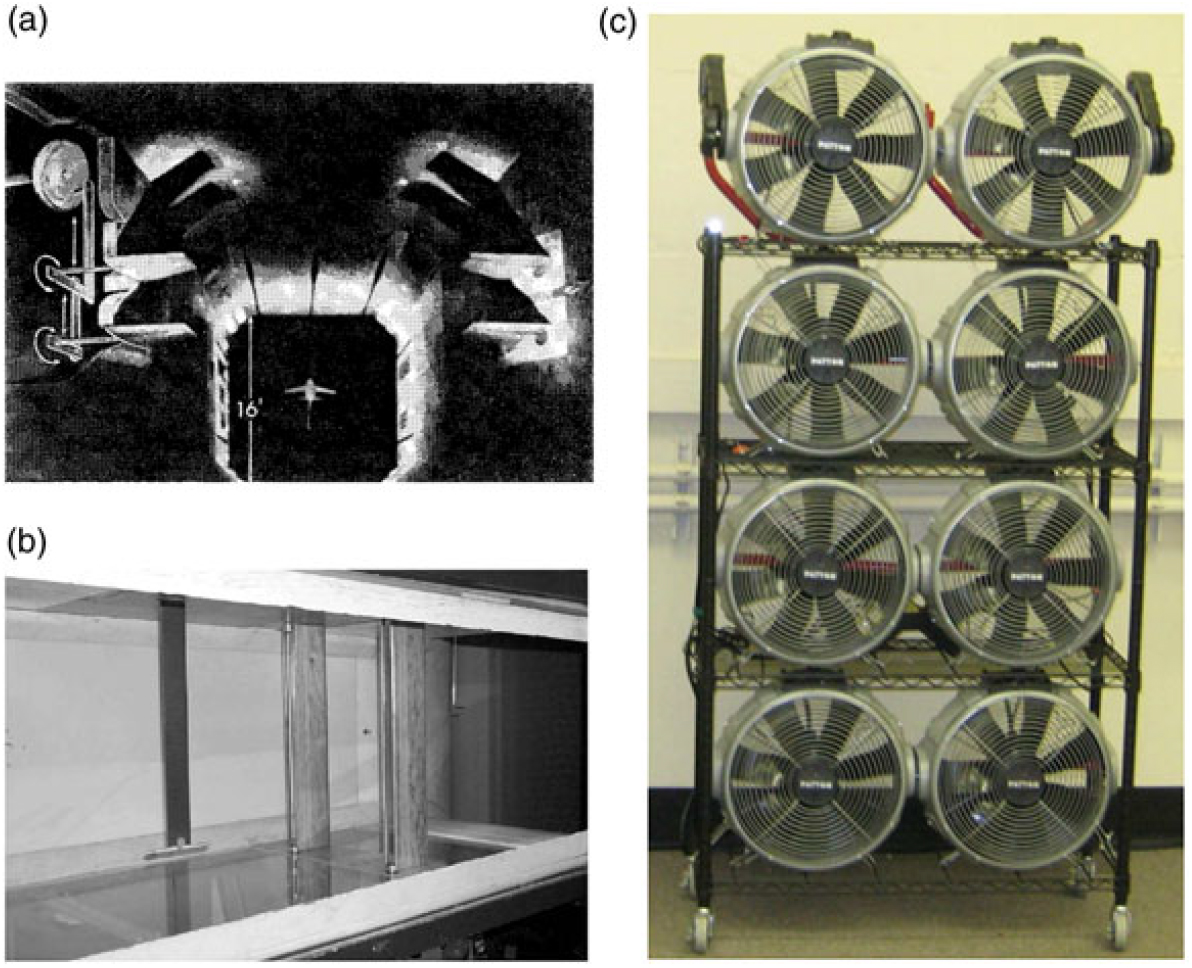
Figure 8. Snapshots of three major kinds of gust generators in tunnels.
For studying gust effects on MAVs experimentally(Reference Johnson and Jacob61–Reference Zarovy, Costello and Mehta63), recently, a relatively simple design consisting of bank of miniature surplus computer cooling fans to form a gust generation, as shown in Fig. 8(c), has been made. This kind of gust generator is easy to achieve, simple to construct and costs less. However, it is capable of providing relatively simple forms of gust, such as ramp and impulsive sharp-edge gusts or thoroughly random gusts, either in the longitudinal, vertical or lateral directions.
It should be noted that for all wind-tunnel gust simulation approaches, some general criteria for a gust load model need to be met. First, the test model must be stable on the mounting system. Second, all rigid-body modes must be well separated from the structural modes of interest. These two criteria are also applicable on a flutter model. The additional criterion, which is different from flutter modeling is that the distortion of the short-period mode induced by the amounting system must be minimised for gust loads tests.
While the above wind-tunnel facilities have been widely used even nowadays, these are all designed for producing discrete gusts. Ever since the middle stage of the gust research history, there have also been great efforts for generating a continuous spectrum of turbulence in line with that of the atmospheric boundary layer, of which much has been made in the field of generating isotropic, homogeneous turbulence with grids(Reference Rosen64–Reference Kumar, Raghavan and Sundararajan69). The most typical and famous work is the application of a wire grid to generate such continuous gusts by Compte-Bellot and Corrsin(Reference Comte-Bellot and Corrsin70,Reference Comte-Bellot and Corrsin71) . While the work paved the way for grid generated turbulence, a major drawback of that method and later passive grid methods is the limitation of the length scale of generated turbulence and the inability of adjusting the turbulence levels with respect to a given flow velocity. To overcome these shortcomings, active grids are necessarily adopted, of which the most successful representative is the one designed by Makita(Reference Hideharu72), which is capable of generating large-scale continuous turbulence in small wind tunnels. Generally, passive grids are often referred to ‘biplanar’ because the vertical and horizontal bars are adjacent to each other but do not intersect directly(Reference Roadman and Mohseni73). While the vertical and horizontal bars of active grids intersect directly, each bar is independently actuated using DC, AC, or stepper style motors, a simple view of this type of grid is shown in Fig. 9. These grids incorporate a series of rotating, diamond-shaped wings to generate small vortices shed off the diamond-shaped wings, while larger eddies can be generated from various parts of the grid opening and closing separately.
Figure 9. Active grid gust generator(Reference Poorte and Biesheuvel74).
3.2 Analytical modeling
The foundation of modern unsteady aerodynamics was built by Wagner(Reference Wagner75) and extended by Jones(Reference Jones76) to finite aspect ratio wings. Küssner first developed a ‘discrete gust’ approach to derive the solution of the response of an airplane to gusts by applying Wagner’s lift-lag function(Reference Kussner77). Up to the mid-1950s, the “discrete gust” approach to gust loads was practically prevailing. In this approach, gust is assumed to possess a fixed and relatively simple shape (generally is as a ram or ‘one-minus-cosine’ function with a fixed wavelength in feet or wing chord length) and variable amplitudes. Although this assumption does not reflect the behaviour of real gusts, yet this approach has worked well and is still adopted by the aircraft industry and the main aviation authorities. In the late 1940s, the ‘spectral method’ was introduced to continuous random gust load research. In this approach, gusts are assumed as examples constituting a continuous random process with a deterministic spectral density. Using this spectral density in a linear system, the dynamics of the aircraft for both rigid-body and aeroelastic properties can be easily calculated. For both the discrete and continuous gust models, practical gust analyses are often achieved by establishing linear governing aeroelastic equations of motion with linear aerodynamics in both time and frequency domains. The Fourier transform (a special case of which being the Laplace transform) of a specific gust wave form has facilitated the development of frequency domain approaches. Alternatively, reduced order models (ROM) developed by using time history data of an appropriate parameter set for an aeroelastic model can be incorporated into a linearised state-space model for closed loop analysis. Time-domain gust analysis has historically been conducted using a panel code where a perturbation in the velocity is introduced to account for a local angle of attack increment.
The most remarkable advantage of the analytical modeling approach is its simplicity and facility for linear gust response analysis. In particular, this approach is best suitable for preliminary flight vehicle design on the basis of certification regulations. However, this approach has also some intrinsic disadvantages. The first and perhaps the most predominant disadvantage is its inability of flow field calculation. As a consequence, an accurate load prediction is impossible. Second, for the reduced order approaches, the ROM and the aerodynamic response data needed to construct the model must be generated in advance. Third, linear gust aerodynamics may not be adequate for highly flexible vehicles designed to fly in the transonic flight regime.
3.2.1 Review of recent codes
Codes for gust response analysis in two-dimensional flow cases have been developed and validated by numerous researchers. Marzocca et al.(Reference Marzocca, Librescu and Chiocchia78) developed a code to analyze the aeroelastic response to time-dependent gust and explosive loading excitation of a two-dimensional rigid or elastic lifting surface featuring plunging-pitching coupled motion. Dessi and Mastroddi(Reference Dessi and Mastroddi79) established a code using similar approach to analyse the stability and gust response of a nonlinear aeroelastic airfoil system exhibiting limit-cycle oscillations (LCO) as well as the mechanism of limit-cycle (LC) excitation. Patil and Taylor(Reference Patil and Taylor80) added gust functionality to the code(Reference Patil, Hodges and Cesnik81,Reference Patil and Hodges82) for calculation of gust response of high-altitude, long-endurance (HALE) aircraft based on their work over the past decade in the area of nonlinear aeroelasticity. The aeroelastic model is based on a geometrically exact, nonlinear beam model coupled with large angle aerodynamic model. The gust response calculation is based on the Fourier superposition of the response to simple harmonic gusts. Later Patil(Reference Patil83) added a transient gust analysis capability to NATASHA. The gust input as a function of time is calculated from the known von Karman power spectral density as a weighted sum of sinusoids at random phases. The response stochastic parameters can be calculated from the response time series. Pettit et al.(Reference Pettit, Hajj and Beran84) and Ghommem et al.(Reference Ghommem, Hajj, Pettit and Beran85) developed stochastic approaches for modeling incident gust effects on flow quantities, in which the gust loads are computed using the unsteady vortex lattice model, which includes temporal variations in wake vorticity and the associated downwash on the airfoil.
Three-dimensional gust response codes have also been extensively developed. The commercial aeroelastic analysis software NASTRAN(Reference Rodden and Johnson86) is one of the earliest codes that employ the DLM to calculate aerodynamic loads in aeroelastic analysis, including flutter and gust loading and has been applied by many gust researchers like Karpel et al.(Reference Karpel, Moulin, Anguita, Maderuelo and Climent87). For private cases, Tang, et al.(Reference Tang and Dowell53,Reference Tang and Dowell54) developed an aeroelastic approach to study the effects of a steady angle of attack on the nonlinear aeroelastic response of a delta wing model to a periodic gust. In their approach, a three-dimensional time-domain vortex lattice aerodynamic model and a reduced order aerodynamic technique were used. Drela(Reference Drela88) developed ASWING, a licensed integrated analysis tool for aerodynamic, structural and control simulation of flexible aircraft in extreme fight conditions. The code uses an unsteady compressible vortex/source-lattice aerodynamics model based on the lifting-line theory and joined nonlinear isotropic beam structural model allowing arbitrary large deformations. Gust field inputs can be specified. The fully Nonlinear Aeroelastic Simulation Toolbox (NAST) has been developed in a joint effort, which incorporates the aerodynamic formulation from Peters and Johnson(Reference Peters and Johnson89) and the strain-based structural modeling approach from Cesnik and Brown(Reference Cesnik and Brown90,Reference Cesnik and Brown91) . Later it is also with the flexibility of fuselage and vertical tail considered(Reference Cesnik and Su92). It has been demonstrated that this code enables a transient analysis of gust response and flight dynamics of various wing configurations, such as single-wing and joint-wing(Reference Cesnik and Su92–Reference Su and Cesnik95). Approaches for gust response analysis using ROMs are widely applied, such as by Gennaretti and Mastroddi(Reference Gennaretti and Mastroddi96), Raveh(Reference Raveh97), Zaide and Raveh(Reference Zaide and Raveh98), Zhang, et al.(Reference Zhang, Ye, Yang and Shi99), etc.
3.2.2 Representative results
In this subsection, the representative characteristics of gust response of flight vehicle obtained by the foregoing analytical formulation method will be discussed.
(1) Time domain
Consider a random vertical gust velocity having a time history as the black curve in Fig. 10 shows. The resulting time history of the flight vehicle motion will have the form shown by the red curve in Fig. 10, which has a certain well defined frequency with modulated, randomly varying amplitude. The more random input has been filtered by the aeroelastic transfer function, the more portion of the gust velocity signals which has frequencies near the natural frequencies of the flight vehicle will be identifiable in the response. This characteristic is more easily to be observed in the frequency domain than in the time domain.
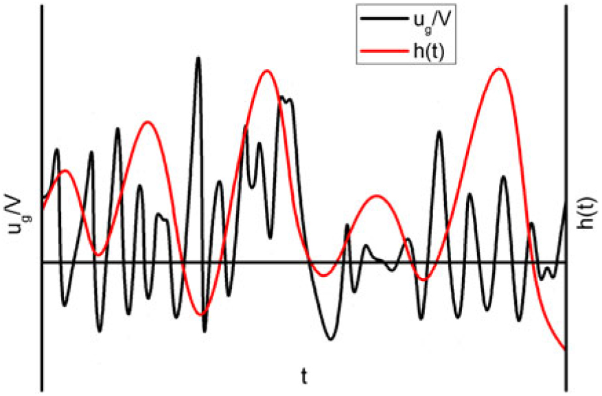
Figure 10. Typical altitude response to a random vertical gust(Reference Dowell100).
(2) In the frequency domain
Figure 11 illustrates a typical gust spectrum, the transfer function at some flight speed and the resulting response spectrum in the black, red, and blue curves, respectively. Note that herein for brevity, the three curves are plotted with the same horizontal coordinate whereas the vertical coordinates have different scales for each curve. It is clearly seen that the aircraft response spectrum varies synchronously with the aeroelastic transfer function. Both of the curves increase first with the frequency ω to their resonant peaks. There is a special case where the aeroelastic system experiences dynamic instability at this moment, i.e., flutter, the two peaks would essentially collapse into one and the amplitude of the vertical displacement would become infinite. Afterwards, both of the transfer function and response spectrum curves decrease to a low level and again increase gradually to another peak and so on.
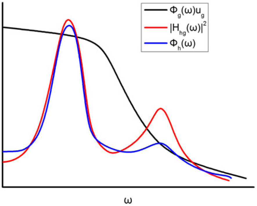
Figure 11. Typical results regarding a random vertical gust(Reference Dowell101).
3.3 CFD numerical simulation
Regarding the foregoing disadvantages of the analytical modeling and experimental measurement approaches, a less-expensive CFD numerical simulation of gust response, especially for highly flexible vehicles, is required. High fidelity CFD solutions are sought during the detailed design stages for accurate results for cruise, as well as to correct panel method solutions for nonlinearities.
A common aeroelastic CFD simulation of gust modeling must include a fluid solver, a structural solver, a mesh deformation module and a fluid-structure interaction (FSI) module, which performs the mapping of aerodynamic force to the structural model. Generally the mapping of structural deformation to the aerodynamic model(Reference Dimitriadis, Vio, Cooper and Badcock102) is used to generate a CFD code with gust modelling capability. The primary element is to develop a general CFD code which can solve either Euler or Reynolds averaged Navier-Stokes (RANS) flow equations. The gust models are then incorporated in the CFD code with aeroelastic capabilities to perform fluid-structure coupling simulations. Concretely, a gust is defined by convecting disturbances from unsteady Farfield Boundary Conditions (FBC). The numerical dissipations or losses associated with CFD can be reduced i.e. upstream farfield, where gust disturbances can be diffused rapidly. The high grid resolutions all over the fluid domain or grid adaptation along the gust path are usually adopted to change the volume of grid cells as gust disturbances move. The Geometric Conservation Laws (GCL) must be satisfied to avoid spurious source terms(Reference Dowell101). While this approach can be interpreted easily, high spatial resolution is required to minimise the numerical losses in the process of gust transport. The TAU is only of second order accuracy in space. A solution of using the chimera mesh technique was proposed by Heinrich and Reimer(Reference Heinrich and Reimer103). The gust is transported through a chimera mesh, whose dimension is of the same order of magnitude as the gust wavelength, thus greatly lowering the mesh requirement.
On the other hand, to overcome the requirement for a fine mesh in the farfield of the CFD domain, the Field Velocity Method (FVM)(Reference Singh and Baeder104) (also called as the grid velocity method(Reference Dowell101) or the Disturbance Velocity Approach (DVA)(Reference Heinrich and Reimer103,Reference Heinrich and Michler105) ) has been developed by prescribing gust velocities and modifying grid time metrics. This scheme is widely employed to simulate grid motion without actually distorting the mesh. The remaining mesh is solved without numerical dissipation of the disturbances. The allowing coarser meshes take burden away from the airfoil and result in reducing computational costs significantly. Another outstanding advantage of this method is that it can also be used to simulate a step change in angle of attack by incorporating a step change in vertical grid velocity all over the flow domain. Such practice effectively decouples the influence of pure angle of attack from that of a pitch rate because the airfoil is made not to pitch and the step change is uniformly enforced over the entire flow domain. A special case of the FVM is the widely used indicial method for simulation of sharp-edge gust response(Reference Leishman106–Reference Bai and Wu109). However, while FVM accounts for the influence of the gust on the aircraft, it is unable to predict the feedback of the aerodynamics of the aircraft on the gust shape(Reference Heinrich and Reimer103), as well as the downstream horizontal stabiliser and wakes. The Split Velocity Method (SVM)(Reference Huntley, Jones and Gaitonde110,Reference Huntley, Jones and Gaitonde111) is an extension of the FVM, which prescribes gust velocities but retains all momentum and energy components by rearranging the unsteady governing equations on a fixed mesh. This results in source terms that account for all the gust-airfoil interactions and provides more accurate solutions for both inviscid and viscous flows(Reference Huntley, Jones and Gaitonde110,Reference Wales, Jones and Gaitonde112) . The FVM and SVM are both prescribed velocity methods. In addition, Heinrich proposed a Resolved Gust Approach (RGA)(Reference Heinrich and Reimer103,Reference Wu, Bangga and Cao113) , which implements this approach using the chimera mesh technique(Reference Heinrich, Siegfried, Ulrich, Hans-Joachim and Reinhard114). The gust can be fed into the discretised flow field using an unsteady boundary condition at the far-field boundaries. The advantage of the method is that the mutual interaction of gust and aircraft is captured, since the gust is resolved in the flow field. A “gust transport mesh” technique was developed within the chimera mesh to minimise the effort necessary to transport a gust through the discretised flow domain from the inflow boundary to the aircraft body(Reference Heinrich and Reimer103).
3.3.1 Fluid-structure coupling strategy
(1) Fluid solver
As for full CFD simulations, the basic flow governing equations are the well-known unsteady Navier-Stokes (NS) equations. For RANS strategy of the NS equations in the turbulent regime, turbulence models ranging from eddy-viscosity models (EVM), nonlinear eddy-viscosity models (NLEVM) and differential stress models (DSM)(Reference Sodja115) can be employed to model the mean turbulent stress in the fluid. The specific turbulence models can be referred to in Ref. Reference Wilcox116. However, to obtain high-fidelity simulation of flow turbulence, the time-variant flow should be directly solved with no turbulence modeling, i.e., the so-called Direct Numerical Simulation (DNS). All scales of the flow must be resolved, thus requiring enormous computational resources even for a simple 2D plate flow. Considering this, a compromise solution named RANS-LES (Large-Eddy Simulation, which was initially proposed by Smagorinsky(Reference Smagorinsky117)) is a suitable alternative. Using this method, one computes the turbulence in the small-scale flows such as near-wall(Reference Piomelli and Balaras118,Reference Spalart119) , reacting(Reference Pitsch120) and multiphase flows(Reference Fox121) with the help of turbulence models, while solves the larger-scale flows via low-pass filtering of the NS equations without any turbulence models. This practice not only reduces the computational cost for the small-scale flow regions relative to the DNS but also enhances the fidelity of turbulence calculation in the other larger-scale regions in terms of the RANS solution.
There are many strategies for grid deformation in the CFD domain that can be used, such as those depicted in Refs. Reference Heinrich and Reimer103 and Reference Reimer, Ritter, Heinrich and Krüger122. However, whatever grid deformation methods are adopted, the fulfillment of the geometric conservation law (GCL) is necessary. The GCL is used to satisfy the conservation relationships of the surfaces and volumes of the control cells in moving or deforming meshes. Primarily, the GCL requires that the changes in the volume of a moving cell must be equal to the sum of the changes along the surfaces that enclose the volume(Reference Dowell101).
The GCL has the following form
 $$\Lambda (t_2 ) - \Lambda (t_1 ) = \int_{t_1 }^{t_2 } \oint_{S(t)} {V_s} \cdot ndSdt$$
where Λ(t 1) and Λ(t 2) are the initial and final elementary volumes. Vs and n are respectively the moving velocity and the normal direction of the cell surface S(t) at time t. This equation needs to be satisfied in order to make the numerical discretisation strictly conservative or artificial sources and sinks may be produced. Thomas and Lombard(Reference Thomas and Lombard123) proposed the same differencing schemes to solve this equation as that used for flow conservation equations. However, this practice brings extra computational cost. Sitaraman and Baeder(Reference Dowell101) suggest a more practical approach proposed by Vinokur(Reference Vinokur124), which computes the Jacobian J by its geometric definition and calculate the time metrics according to the geometric conservation law.
Equation (73) naturally leads to an introduction of the gust velocity Vg depending on both the spatial coordinates (x, y, z) and the time variable t as a part of the grid deformation speed
 $$V_s = V_{grid} + V_g $$
where Vgrid denotes the velocity of the grid structural deformation due to aerodynamics and wall motion during flight. Equation (17) allows to check the GCL condition with considering a gust velocity.
As discussed in the methodology section, generic gust modeling with grid deformation requires huge computational resources. Various prescribed grid velocity methods have been developed which incorporate the gust influence by changing the gust-resulted grid velocity without actually distorting the mesh. The field velocity method (FVM) is one of the most widely used methods.
Mathematically, the FVM can be explained by considering the velocity field V, written in the physical Cartesian domain as
 $$V = (u - x_\tau )i + (v - y_\tau )j + (w - z_\tau )k$$
where u, v and w are the components of the velocity along the coordinate directions. x τ , y τ and z τ are the corresponding grid time velocity components. For a stationary aircraft, these components are zero while for a dynamic mesh they are nonzero due to the kinematic behaviour of the mesh. The FVM changes the velocity field through the grid velocity. Assuming there is an external gust disturbance having velocity field Vg = (u g, v g, w g), the velocity field with gust existence becomes
 $$V = (u - x_\tau + u_g )i + (v - y_\tau + v_g )j + (w - z_\tau + w_g )k$$
Therefore, the modified grid velocity becomes
 $$\hat x_\tau i + \hat y_\tau j + \hat z_\tau k = (x_\tau - u_g )i + (y_\tau - v_g )j + (z_\tau - w_g )k$$
Once the grid velocity is changed, the grid time metrics in the computational domain  $( \hat \xi _t ,\hat \eta _t ,\hat \zeta _t )$ are updated as
 $$\matrix{{\hat \xi _t = - (\hat \xi _x \tilde x_\tau + \hat \xi _y \tilde y_\tau + \hat \xi _z \tilde z_\tau )} \hfill \cr {\hat \eta _t = - (\hat \eta _x \tilde x_\tau + \hat \eta _y \tilde y_\tau + \hat \eta _z \tilde z_\tau )} \hfill \cr {\hat \zeta _t = - (\hat \zeta _x \tilde x_\tau + \hat \zeta _y \tilde y_\tau + \hat \zeta _z \tilde z_\tau )} \hfill \cr } $$
(2) Structural solver
Structural models are used to calculate the structural deformation of the body due to all kinds of loads including the external gust loading. Theoretically, nearly all models available for generic grid deformation issues can also be applied on gust-induced structural response. Compared to aerodynamic models, structural models are much coarser(Reference Karpel, Moulin, Anguita, Maderuelo and Climent87,Reference Khodaparast and Cooper125) . Here, we primarily introduce a common dynamic Finite Element Method (FEM) structural model adopted by Reimer et al.(Reference Reimer, Ritter, Heinrich and Krüger122). In this model, the elastic and inertia modules are independently established in order to avoid spurious low-frequency skin modes. Hence, two different mesh systems exist for the two modules. For every mass case studied, the following generalised eigenvalue problem (EVP) is resolved:
 $$K\delta _i = \lambda _i M\delta _i ,\;\;\;\;i = 1, \cdots ,n_{DoF} \;(n_{DoF} = n_r + n_e )$$
where K and M denote the stiffness matrix and mass matrix of the unconstrained aircraft, respectively. δ i and  $\lambda _i = \omega _i^2 $are the i − th M normalised eigenvector and the corresponding eigenvalue. Note that the n r rigid body modes should be removed from the above resolved eigenmodes to account for the n e elastic modes. Finally, the derived elastic modes are used by the modal structural solver in NASTRAN to compute the elastic aircraft deformation.
(3) Fluid-structure coupling
In aeroelastic problems where both the elastic and inertia modules have their own mesh system, a critical consideration is the bridging of the CFD module and the CSD (Computational Structure Dynamics) module. The consistent computational aerodynamic forces calculated by the CFD solver on the CFD mesh must be transferred correctly to account for the deformation of the CSD mesh, and vice versa. The changed structural displacements of the CSD mesh must be translated properly into a smooth deformation field of the CFD mesh. In this coupling iteration, data interpolation methods are needed for both the displacement and load interpolations.
3.3.2 Review of recent codes
Codes for generic gust modeling with grid deformation have been developed by Liauzun at ONERA(Reference Liauzun126), Yang and Obayashi(Reference Yang and Obayashi127), Neumann and Mai(Reference Neumann and Mai128), etc.
Codes for gust modeling with prescribed grid velocity methods are more widely practiced due to its fewer requirements for mesh resolutions, such as Parameswaran and Baeder(Reference Parameswaran and Baeder107), Singh and Baeder(Reference Singh and Baeder104,Reference Singh and Baeder129) , Sitaraman and Baeder(Reference Dowell101), Bartels at NASA(Reference Bartels130,Reference Bartels131) , Heinrich and Reimer(Reference Heinrich and Reimer103), Reimer et al.(Reference Reimer, Ritter, Heinrich and Krüger122), Wales et al.(Reference Wales, Jones and Gaitonde132), Huntley et al.(Reference Huntley, Jones and Gaitonde110), etc.
3.3.3 Representative results
Neumann and Mai(Reference Neumann and Mai128) developed an improved finite element model of the Aerostabil-B model associated with the DLR (German Aerospace Center) code TAU to study the effects of periodic and transient gusts on an elastic wing and compared the numerical results with their previous wind-tunnel experimental results(Reference Mai, Neumann and Hennings57), as shown in Fig. 12. The rigid wing upstream acts as an active gust generator to produce arbitrary forms of gusty wakes to immerse the elastic wing downstream. The upper right graph shows that a very good agreement has been achieved between the numerical and experimental results of rigid wing pressure coefficient. The lower graph in Fig. 12 shows the local pressure distributions of the elastic wing for three different spanwise positions. It can be stated that for each position the agreement is satisfactory on both the suction and pressure sides of the elastic wing except the slightly smaller simulation results at the leading edge area. Particularly, the increasing suction pressure at the chordwise positions between 50 and 75% chord is well predicted in the first two spanwise sections. This is the consequence of the gust-induced local cross-section deformation of the model.
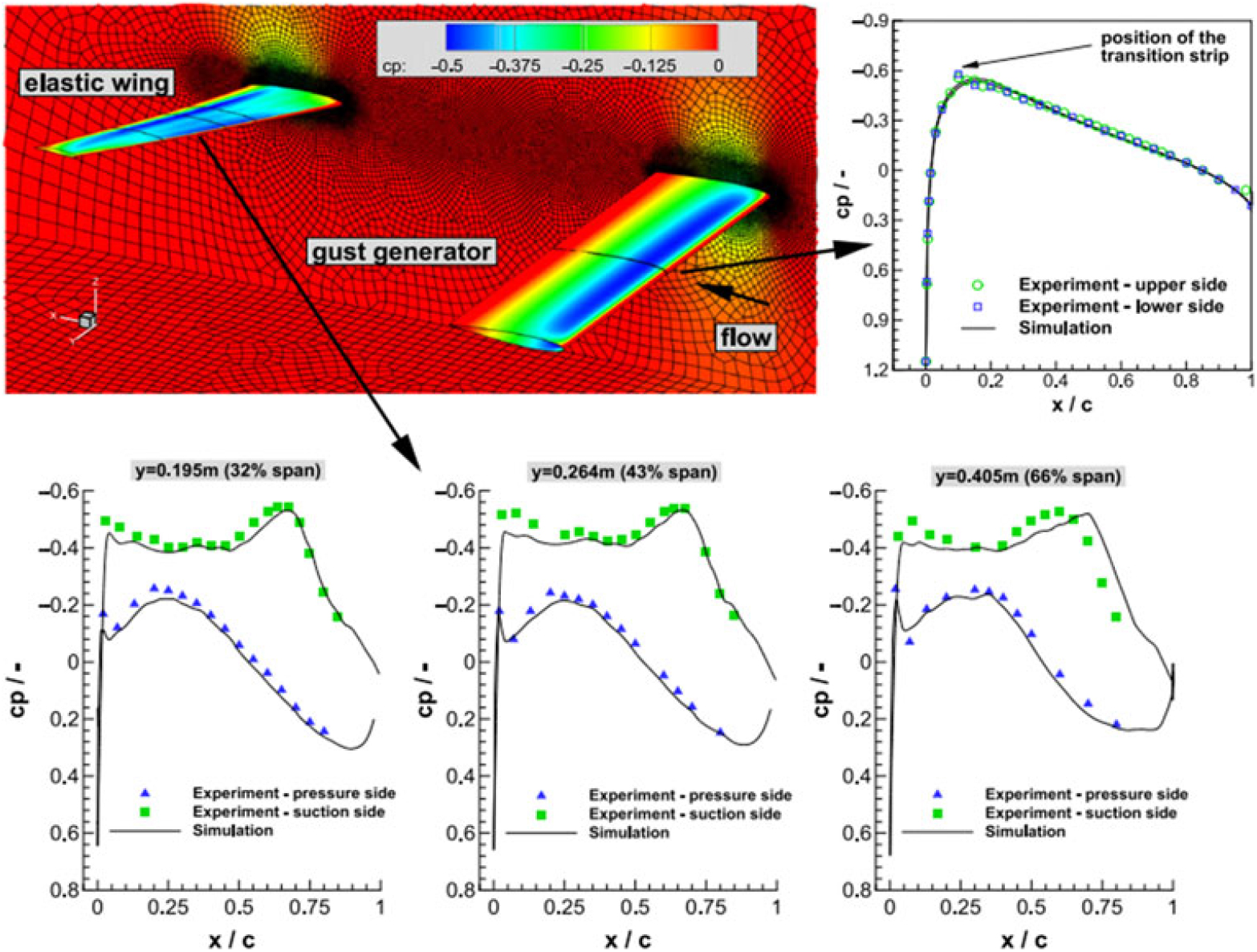
Figure 12. Comparison of the CFD predicted and experimental pressure coefficient of the elastic wing(Reference Neumann and Mai128).
Figure 13 shows a comparison of time histories of the normalised lift and moment coefficients of a truss braced wing aircraft given by the ROM model and the FUN3D simulation for the one-minus-cosine gust conducted by Bartels(Reference Bartels131). The FUN3D was originally developed by NASA where gust modeling capability is embedded with the FVM approach(Reference Bartels130). It is clear that both methods do a good job in modeling the perturbation in the lift and moment coefficients due to the gust and show the same trend. However, both the lift and moment coefficients results clearly show a drift in the FUN3D solution in the last period of tracing time. This reflects the nonlinear property of the FUN3D solution, which becomes clearer and more important within longer simulation time.
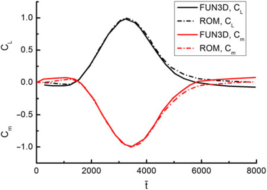
Figure 13. Comparison of the CFD and ROM predicted lift and moment coefficients(Reference Bartels131).
3.4 Reduced order modeling
Although gust loads are predictable with increased fidelity at nonlinear conditions via full-order CFD simulations, the computational cost is overwhelming even for a single simulation(Reference Henshaw, Badcock, Vio, Allen, Chamberlain, Kaynes, Dimitriadis, Cooper, Woodgate and Rampurawala133). Reduced order modeling is considered a reasonable approach to give accurate results as well as to overcome high computational cost of full CFD aerodynamic simulations(Reference Lucia, Beran and Silva134). Another intent in pursuing reduced order models (ROMs) is that when the number of a system’s degree of freedom (DOF) is enormous and/or flow-induced nonlinearities are significant in the aerodynamic response, the analytical derivation of response functions or the linearised approximations to represent the gust-generalised aerodynamic forces (GGAFs) are no longer practical.
ROMs are relatively simple low-order models that capture the nonlinear flow characteristics and significantly reduce the computational cost compared to the full CFD simulation. A typical aeroelastic system outputs the unsteady aerodynamic forces that develop in response to structural elastic motions (inputs). The aerodynamic ROM can be coupled with the structural model for aeroelastic analysis by developing reduced-order analytical formulation or by replacing the full-order CFD solution in a time-marching CFD simulation. Thus, CFD-based ROMs generally can be obtained from either or both of the two aspects. So far, many order reduction techniques or algorithms have been developed and applied such as the convolution integral(Reference Ghoreyshi and Cummings135–Reference Raveh137), Auto-Regression Moving Average (ARMA)(Reference Zaide and Raveh98,Reference Raveh137–Reference Cowan, Arena and Gupta140) , Eigenvalue Realisation Algorithm (ERA)(Reference Wales, Jones and Gaitonde141), Linearised Frequency-Domain (LFD)(Reference Maple, King, Orkwis and Wolff142–Reference Thormann and Timme145), Proper Orthogonal Decomposition (POD)(Reference Dowell, Hall, Thomas, Kielb, Spiker, Li and Denegri146–Reference Thomas, Dowell and Hall148), Alternative Kriging Approach(Reference Cooper, Khodaparast, Ricci, Georgiou, Vio, Trawaglini and Denmer149), Sherman– Morrison–Woodbury (SMW) formula(Reference Khodaparast and Cooper125), and Volterra theory(Reference Silva150,Reference Raveh, Levy and Karpel151) .
4.0 GUST LOAD INFLUENCE
From a design point of view, there are two distinct perspectives with respect to the influences of gusts on aircraft. The first is the effect of gust loads on the flight path of the aircraft. Effective design of auto-pilot or stability augmentation systems requires an accurate estimation of the aircraft dynamic response to the exact type of gusts expected to be encountered. In this respect, the effects of gusts can be further separated into the aspects of aerodynamics and flight dynamics. The second perspective relates to structural excitation of the aircraft, where a gust encounter causes the structural fatigue to the aircraft. In the present section, the influences of gusts on aircraft will be discussed and analyzed from these perspectives.
4.1 Aerodynamics
Figure 14 shows the typical results of the time histories of the lift coefficient (CZ) for an aeroelastic 2-D NLR7301 airfoil under the steady- (black) and unsteady-simulation (red), heave (frequency of 32.88 Hz) and pitch (frequency of 43.27 Hz) coupling (light green) as well as two one-minus-cosine gusts (gust frequency of respectively 78.55Hz and 31.42Hz, blue and deep green)(Reference Liauzun126). In general, both gusts have brought a significant enhancement in the lift relative to the two cases without gust excitation. This encourages us to gather energy from gust loading on aircraft wings and related research have been in progress in this regard(Reference Pozzi, Guo and Zhu152,Reference Xiang, Wu and Li153) .
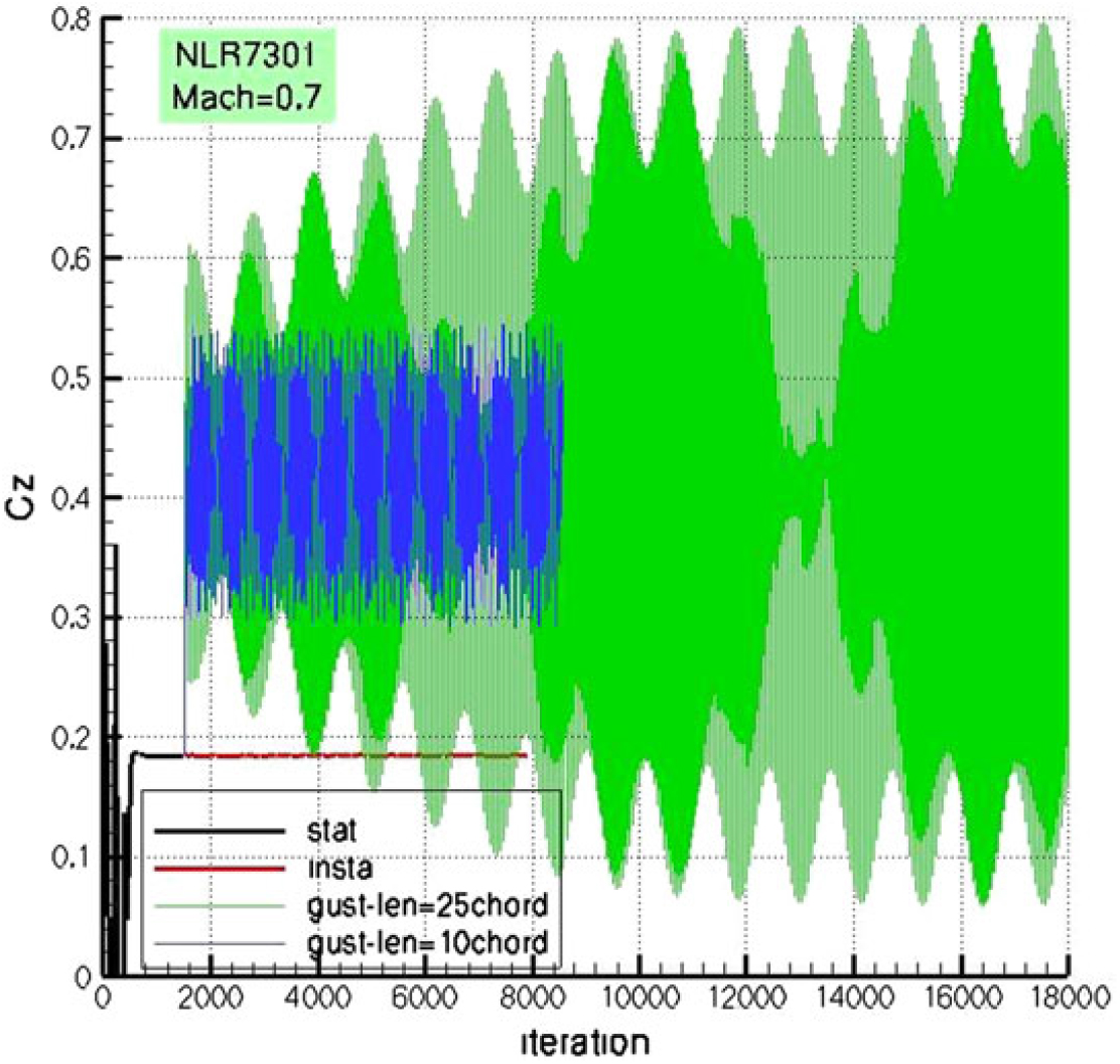
Figure 14. Lift coefficient (CZ) for an aeroelastic 2-D NLR7301 airfoil under different simulation conditions(Reference Liauzun126).
In addition, Fourier transform of the aeroelastic responses to both gusts shows 3 distinct peaks. Considering the wing rigid during a pure aerodynamic response, one periodic response with only one fundamental frequency can be captured, as shown in Fig. 15. However, this structural difference becomes somewhat immaterial in the case of 3D finite-span wings(Reference Liauzun126).
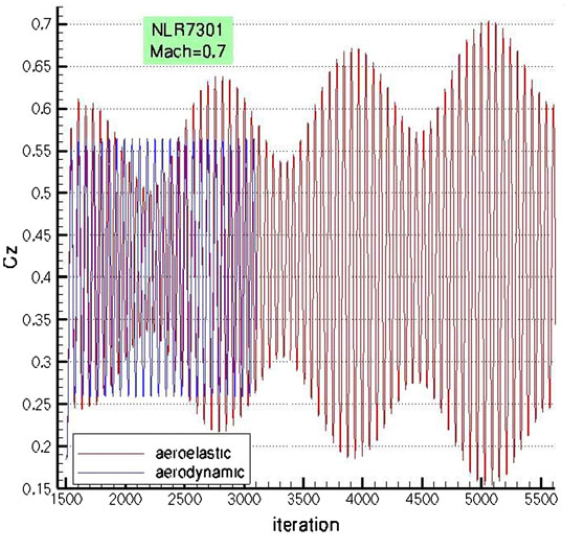
Figure 15. Lift coefficient (CZ) for a rigid and elastic NLR7301 airfoil under the same gust condition(Reference Liauzun126).
Figure 16 presents the gust generalised aerodynamic force (GGAF) response of a generic transport aircraft to a vertical sharp-edge gust in the subsonic flight regime(Reference Raveh97). Remarkable difference between the elastic and rigid configurations can be seen. Before encountering the gust, the aircraft flies horizontally and the generalised force is nearly zero. As the aircraft starts to interact with the gust, the angle of attack increases rapidly, resulting in an abrupt enlargement of the generalised force. Even after the gust has passed, the aircraft remains nose up for some time due to its inertia. Thus, for the rigid configuration, the generalised force increases gently and finally reaches stable condition. The elastic one is capable of performing structural deformations to alleviate the added gust loads, leading to lower aerodynamic loadings. The same result was also observed on a Boeing 737-400 aircraft(Reference Fidkowski, Kroo, Willcox and Engelson154). This conclusion is validated to also hold true at least in the transonic flight regime(Reference Raveh155). Longer stabilising time and more intense oscillations in response to the gust exist simultaneously. This leads to the accumulation of structural fatigue and reduction in the structural lifetime. It reminds people to pay more attention to gust loading on elastic aircraft, particularly for highly flexible vehicles.
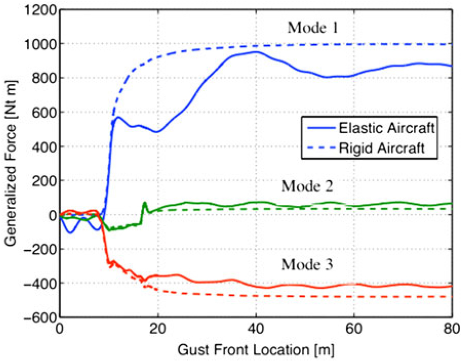
Figure 16. GGAF response of a generic transport aircraft to a vertical sharp-edge gust(Reference Raveh97).
The more general case of a 3D gust will cause an asymmetric response, i.e., a combination of symmetric and antisymmetric responses(Reference Crimaldi, Britt and Rodden156). Thus, it is necessary to have knowledge of the spanwise effect of gust load distribution on the response of the aircraft. Patil and Taylor(Reference Patil and Taylor80) examined the effects of various gust models on the calculated response of a highly flexible aircraft. A uniform gust model executed on a 2D airfoil model, a non-uniform gust model and a spanwise discrete gust model applied on the different spanwise positions of a 3D aircraft model were included. The uniform gust model implies that the gusts over the entire wing are identical and thus are fully correlated on all the spanwise positions. The non-uniform gust model includes only the gust downwashes on the correlation spanwise positions, thus are partially coupled. The spanwise discreet gust model implies that the gust on each span-wise position is independent of other gusts and thus the gusts on all the spanwise positions are completely uncorrelated. Results in Fig. 17 show that the spanwise discrete gust model predicts the highest bending moment because the gusts on all the spanwise positions can be overlapped with each other. While the uniform gust model predicts the lowest bending load due to the fact that all the spanwise gusts are out of phase and cancel each other. The same consequence takes place on the shear force as well. Very recently, Dussart et al.(Reference Dussart, Lone and Guo157) formulated a multidimensional discrete gust model for critical loads assessment. Symmetric and asymmetric discrete gusts, both of which are spanwise varying in terms of vertical velocity in the upward and downward directions, were discussed. A quick view of some of their predicted result of the Wing Root Bending Moment (WRBM) is presented in Fig. 18. Their work shows a strong tool for multiple research topics, including gust loads prediction and alleviation, handling qualities of morphing configurations and exergy analysis.
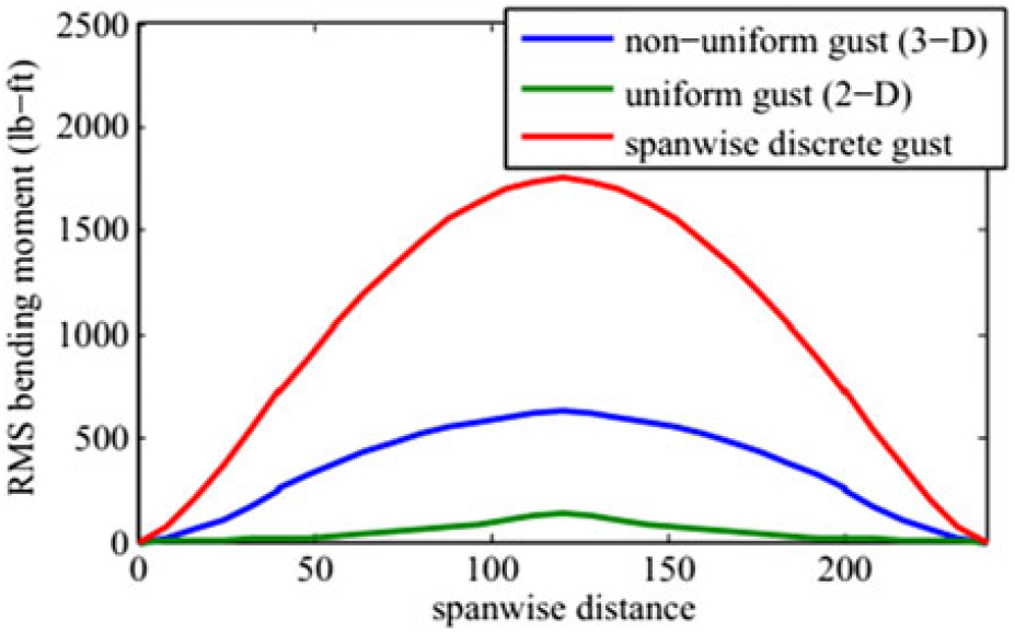
Figure 17. Bending moment of 2- and 3-D configurations under different gusts(Reference Patil and Taylor80).
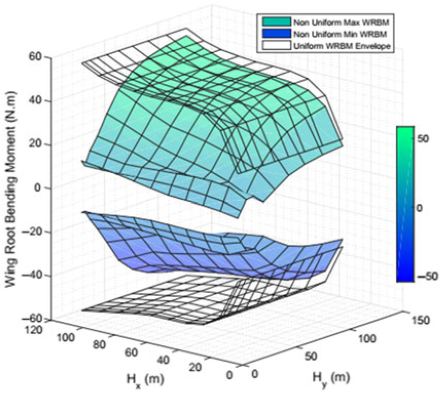
Figure 18. Wing Root Bending Moment predicted using a multidimensional discrete gust model(Reference Dussart, Lone and Guo157).
MAVs are one of the largest groups that are vulnerable to gust loads due to their weakness in resisting gust loads(Reference Johnson and Jacob61,Reference Zarovy, Costello, Mehta, Flynn, Gremillion, Miller, Ranganathan, Humbert and Samuel62,Reference Roadman and Mohseni73,Reference Galiñski158–Reference Golubev and Visbal162) . The flying speed of a MAV is around 10 to 20 m/s, which is at the same scale of the velocity of a normal gust. In addition, a MAV mostly flies within 100 m above the ground, where the shears and gusts caused by terrain obstacles frequently occur. Therefore, there is an emerging necessity of studying the effects of gust loads on MAVs. A systematic research carried out by Viswanath and Tafti(Reference Viswanath and Tafti163) revealed the effect of two gusts of indicial functions on the transient flow structures. Gust produced aerodynamic forces in their study of a flapping MAV are shown in Fig. 19. A major finding in their study is that the effective angle of attack was greatly decreased under the gust loadings, as shown in Fig. 20. Therefore, on application of the gust at t ∗ = 0.22, there is a sharp instantaneous drop in the lift and thrust of the wings. This drop in lift is a direct consequence of the instantaneous drop in the effective angle of attack and the onset of the Leading-Edge-Vortex (LEV) shedding. The two insets show the vorticity contours between the non-gust flow and the gusty flow at t ∗ = 0.29. In the non-gust flow, it is seen that a vortex core just separates from the surface just after the secondary vortex begins to manifest itself. However, in the gust-loaded flow, due to the initial drop in the circulation and the accelerated separation of the LEV at t ∗ = 0.22, the secondary LEV is already well formed at t ∗ = 0.29, which causes the second sudden change in both coefficients. Note that at t ∗ = 0.29 the effective angle of attack is changed from negative in the non-gust condition to a positive value in the gust case. Therefore, both the lift and thrust have obtained a sharp enhancement at this moment. Lian(Reference Lian164) also studied the aerodynamic performance of a flapping airfoil in gusty environment. In his study, he pointed out that flapping wing can reduce the effects of gust under a combination of more than one parameter in wing flapping kinematics.

Figure 19. A view of the MAV motion planes studied in Ref. Reference Viswanath and Tafti163.
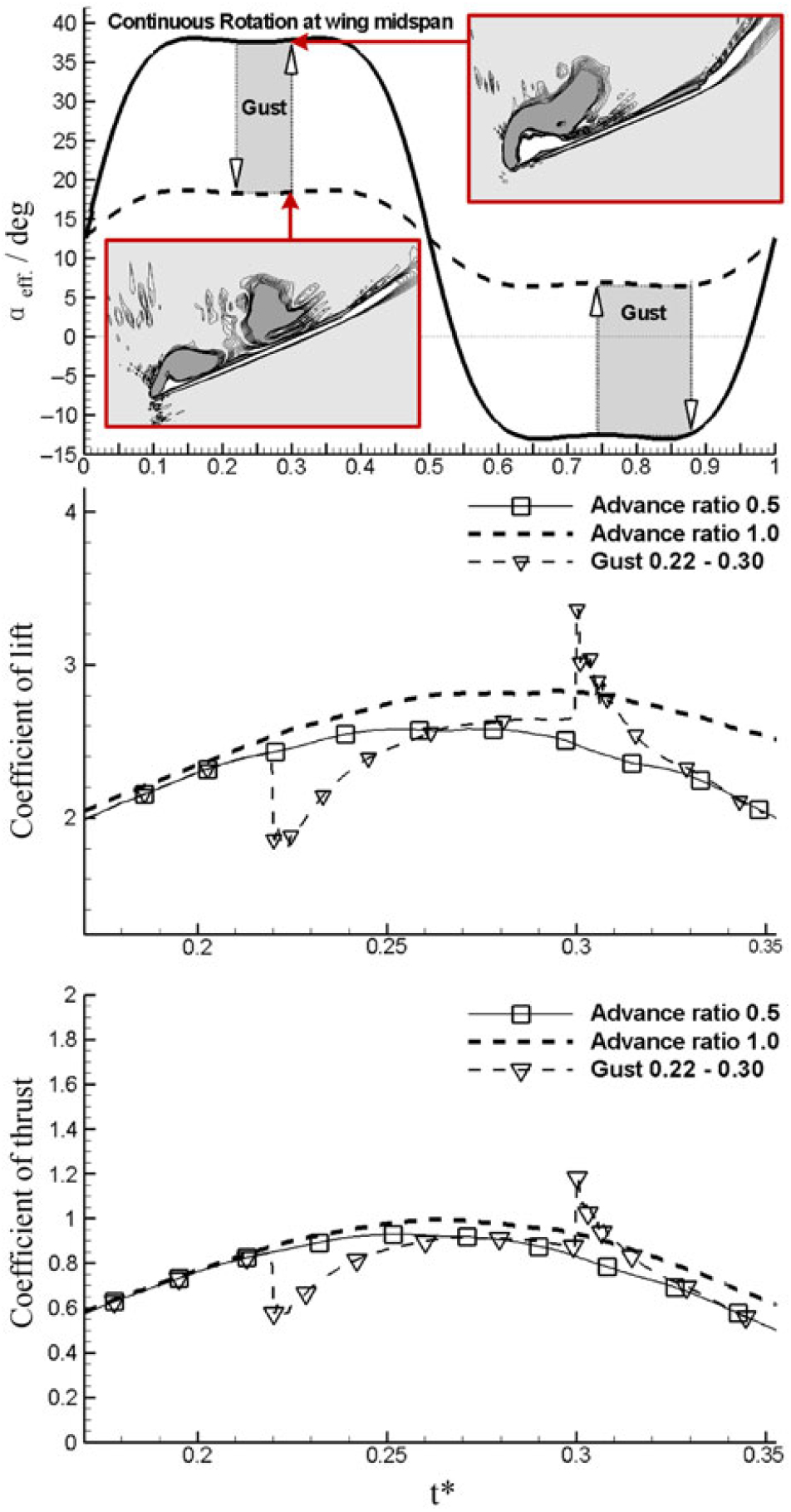
Figure 20. Aerodynamic performance and flowfield characteristics of a flapping wing under different gusts(Reference Viswanath and Tafti163).
Another kind of aircraft which may also be affected by gust loads is rotorcraft. Special attention is paid to the simulation of the unsteady aerodynamic flowfield of such an aircraft, including the Blade-Vortex Interaction (BVI) phenomenon. The airflow field at the rotor is within both the subsonic and supersonic regimes. Therefore, the interaction between the gust and the blade vortex becomes more complex and challenging to predict. Baeder et al. have conducted a series of work on the simulation of unsteady flowfield and the response of the helicopter rotor to stationary and moving gusts using CFD techniques(Reference Dowell101,Reference Singh and Baeder129) . Their results show that for a stationary gust the lift increases smoothly with time. However, for moving gusts, as the gust forwarding speed increases (i.e., the gust advance ratio decreases), the slope of the lift curve at the ascent stage is also increased (see Fig. 21). This is due to the acceleration effect by the impulsive change in the velocity field over a portion of the airfoil. The same results are also obtained by Leishman(Reference Leishman165). As said, a special interest of such rotor cases is the BVI phenomenon. Figure 22 presents the perturbation pressure contours for an indicial gust moving at 0.5 advance ratio. The initial propagation of the disturbances from the leading edge and the subsequent reflected wave from the trailing edge can be clearly seen at the dimensionless time τ = 1.6 and 2.0. As for the effects of blade vortex associated with gusts, two distinct effects were found in literature. The first are the changes in the gust field that lead to the peaks of the aerodynamic forces occurring at different times for different advance ratios and the second is associated with the varying gust response of the airfoil to the moving gusts(Reference Singh and Baeder129).
Figure 21. Lift coefficient of a helicopter rotor under moving gusts(Reference Singh and Baeder129).

Figure 22. Instantaneous contours of pressure of the helicopter rotor under moving gusts(Reference Singh and Baeder129).
All the above depicts the various effects of gust on aircraft longitudinal aerodynamic performance. This usually holds true for conventional aircraft when the longitudinal flight speed is far larger than all the components of the gust. Therefore, the gust-induced aerodynamic forces and moments (except drag) are mostly due to circulation lift as per Bernoulli’s theorem. However, for some unconventional aircraft, such as helicopter and Vertical Take-off and Landing (VTOL) aircraft, in transition to hovering flight, the contribution to the aerodynamic performance due to momentum transfer by the gust can be of the same order of magnitude as that due to circulation lift. So it is necessary to replenish the gust aerodynamic theory for aircraft in the hovering mode. Early in the 1960s, Swaim and Connors(Reference Swaim and Connors166) studied the effects of spanwise distribution of longitudinal and vertical components of gust velocity and longitudinal distribution of the lateral component on the lateral-directional response of a nearly hovering VTOL aircraft, VJ-101. Their results show that the lateral component of the random homogeneous and isotropic gust has the largest effect on both the yawing and rolling moment. These values can be two to three orders of magnitude larger than the least values due to the longitudinal gust velocity component. The longitudinal and vertical components of the gust velocity have no contribution to the side force. Besides, they also explored the penetration effects of the lateral gust velocity component on the yawing, rolling and side force performance. Here, the penetration effects are originated from the non-uniform axial distribution of the lateral gust velocity, while the uniform longitudinal and vertical gust velocity components produce no yawing or rolling moments or side force. Therefore, they have no penetration effects. Results show that the penetration effect’s impact on the yawing moment is quite significant while can be ignored on the rolling moment and side force. The influences of gust penetration and shape on high-forward-speed helicopters were also validated(Reference DREES and Harvey167,Reference Arcidiacono, Bergquist and Alexander168) .
4.2 Structural dynamics
Another direct consequence of gust to aircraft is that it can affect the aircraft structural design loads and fatigue life. This is a prerequisite consideration for aircraft structural design. Figure 23 presents a complete time history of the wing tip bending deflection for a flexible aircraft experiencing stochastic continuous gusts(Reference Fazelzadeh and Sadat-Hoseini169). In the figure, the dashed line stands for the results obtained with the quasi-steady strip theory for aerodynamics and the solid line for the results with Peters’ unsteady aerodynamic model(Reference Peters and Johnson89,Reference Peters, Karunamoorthy and Cao170) . First, at the time interval of 10– 15s, high-frequency bending deformation of the wing tip resulting from the high-frequency gust excitation is obvious. When the gust leaves, the unsteady high-frequency elastic oscillations are almost damped completely by the structural damping of the flexible wings, while the quasi-steady case still exhibits low-frequency oscillations with small amplitudes.
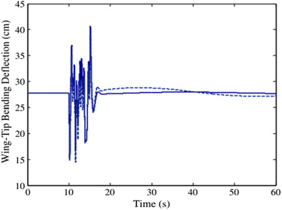
Figure 23. Wing tip bending deflection and torsion of a flexible aircraft experiencing stochastic continuous gusts(Reference Fazelzadeh and Sadat-Hoseini169).
Comparing an airfoil with a plunging-pitching coupling (2-degree-of-freedom, 2-DOF) motion and a 1-DOF (plunging only) motion under a gust, it was found that the addition of the pitching degree of freedom appears to reduce the amplitude of the plunging displacement and acceleration. This effect becomes more significant with lower mass ratio μ and larger plunging stiffness A, as shown in Fig. 24(Reference Marzocca, Librescu and Chiocchia78). This result can be pertinent in the hydroplane design, where the fluid is water and therefore μ is very low. That approach has also been adopted by the current author(Reference WU171) and the same results as in Ref. Reference Marzocca, Librescu and Chiocchia78 are reproduced. This consequence is not difficult to understand. Apparently, the plunging motion provides an additional vertical velocity component, while this actually enhances the airfoil angle of attack. For a longitudinally stable airfoil, the external aerodynamic forces and moments force a pitch down moment of the airfoil to reduce the instability tendency. In addition, the authors also investigated the pitching response to gust under different mass ratio μ and plunging stiffness A, as shown in Fig. 24. It indicates that larger mass ratio μ increases the difference between the 1-DOF and 2-DOF pitching response due to the plunging motion, as the body inertia is increased. However, it is also found that simply changing the plunging stiffness A does not enforce any influence on the pitching response.
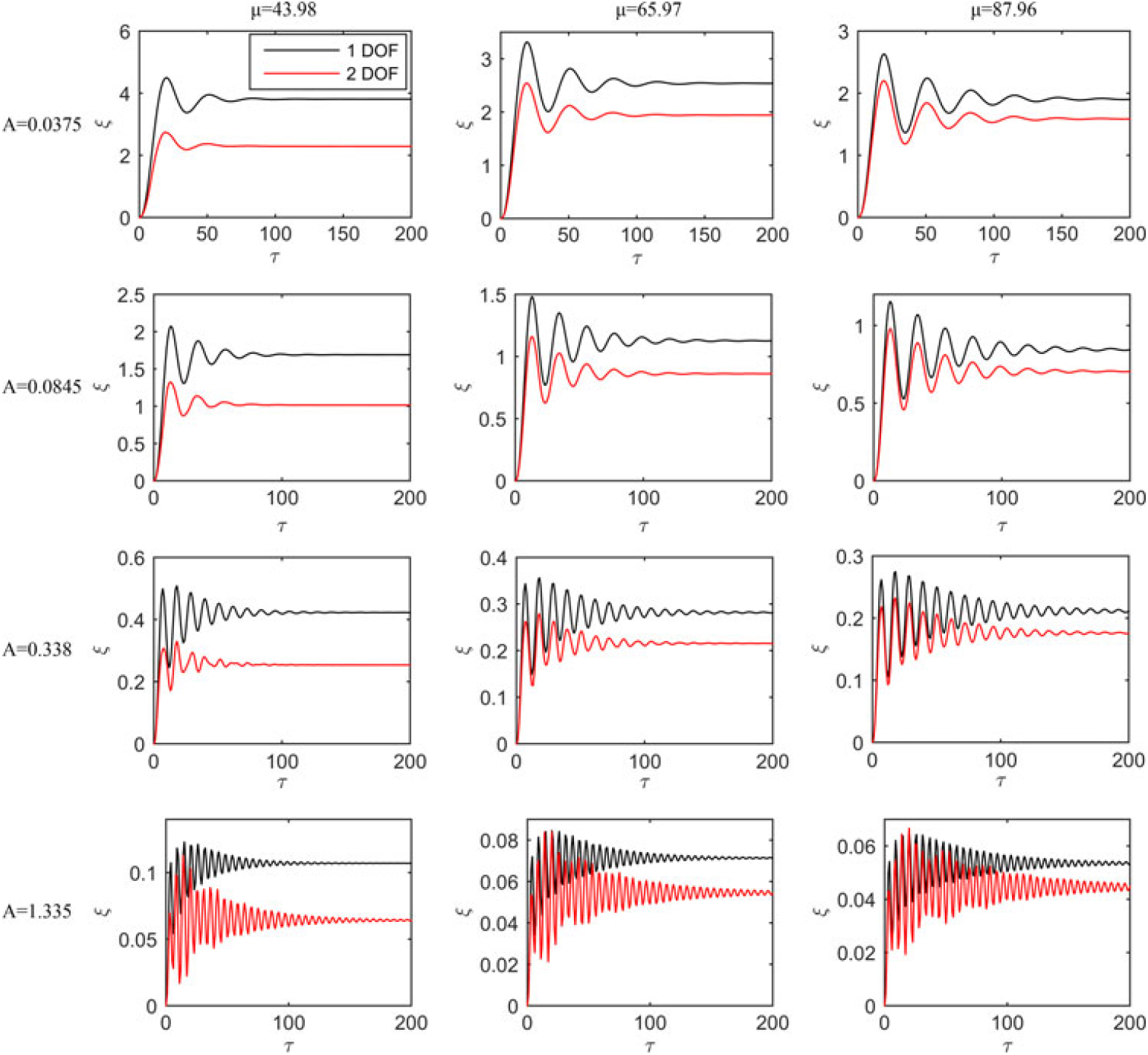
Figure 24. Plunging displacement response for an airfoil under a sharp-edge gust(Reference WU171).
Gust loads are also dominant to structural deformations especially for aircraft with elastic properties. This aspect has been verified quantitatively, as shown in Fig. 25. More flexible configurations experience more adverse oscillating effects by a gust. This undesirable impact becomes more severe with increasing oscillating frequency of the gust (i.e., decreasing gust wavelength). This implies that smaller aircraft, such as MAV and NAV, are more subjected to gust impacts, because on the one hand their light weights are unable to resist gusts and on the other hand resonance is easier to occur due to their comparative spatial scales and flight speeds to gusts. The research of Patil et al.(Reference Stewart172,Reference Moulin and Karpel173) on a HALE aircraft revealed that both the aeroelastic and flight dynamic characteristics of the aircraft can be explicitly changed due to the large deformation of the flexible wings. This leads to the motivation of the research of Su and Cesnik(Reference Cowan, Arena and Gupta140) on the dynamic gust response of a highly flexible flying vehicle featuring light wings with high aspect ratios, as depicted in Fig. 26. The HALE aircraft is part of NASA’s Environmental Research Aircraft and Sensor Technology program aiming at developing UAVs capable of long-duration and very high-altitude flights for atmospheric research(Reference Ricci, Adden, Servadio, Karpel and Cooper174). Although it is not difficult to imagine that the results, based on a scientific approach, verified that the larger gust duration and amplitude produce larger wing root bending curvature as plotted in Figs. 27 and 28, respectively. In addition, the majority of their research work also revealed in detail the effects of gust on the flight dynamics of the same aircraft, as will be discussed in the next subsection.
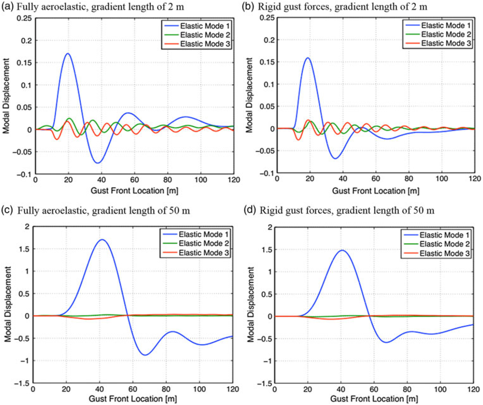
Figure 25. Generalised modal displacements of a flexible aircraft in response to a one-minus-cosine gust at two gust lengths(Reference Raveh97).
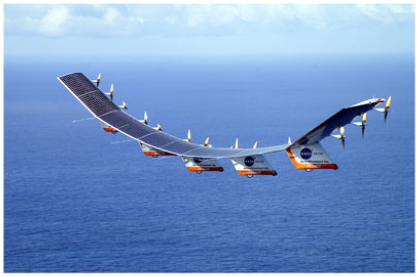
Figure 26. The HALE aircraft developed by NASA(Reference Su and Cesnik94).
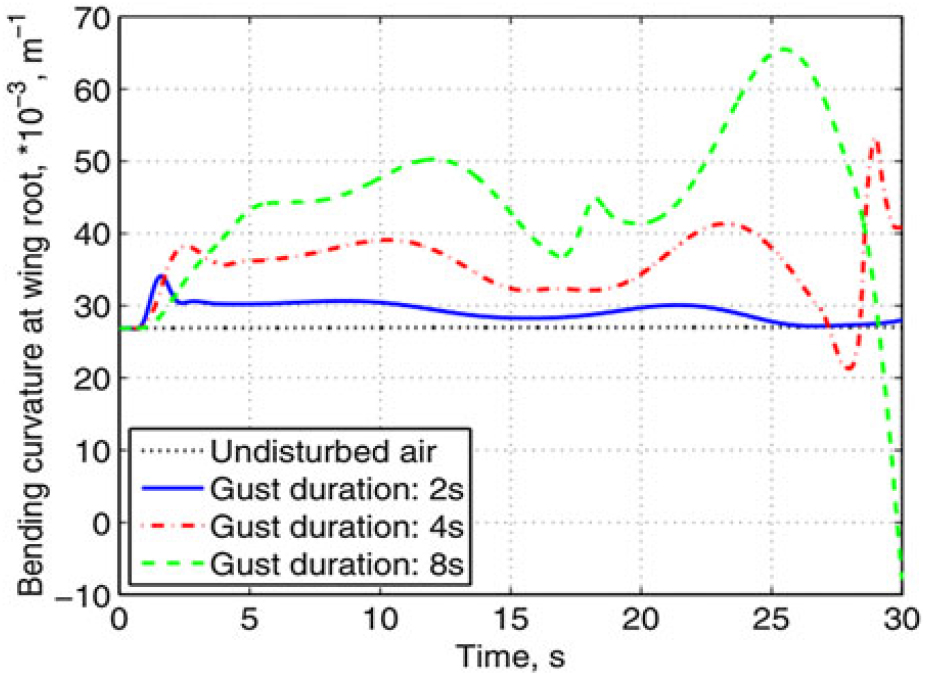
Figure 27. Wing root bending curvature at different gust durations(Reference Su and Cesnik94).

Figure 28. Wing root bending curvature at different gust velocities(Reference Su and Cesnik94).
The nonlinearity have an important effect on the aeroelastic response to gust, especially for very flexible aircraft. A partial view of these effects is available in Fig. 29, where the time histories of the AOA response of a MAV airfoil to a non-uniform, unsteady incoming gusty flow are shown using both linear and nonlinear structural models(Reference Golubev, Dreyer, Hollenshade and Visbal175). The long-term responses seem to be similar for both the frequency and amplitude of the LCO of the airfoil structure. However, significant discrepancies can be seen between the two structural models in the transient process between 50 s and 170 s. Particularly based on the nonlinear model with rich spectra of low-amplitude transient modes, the high-amplitude oscillations around the LOC frequency of 0.6 Hz are disappeared, before reaching the final LCOs.
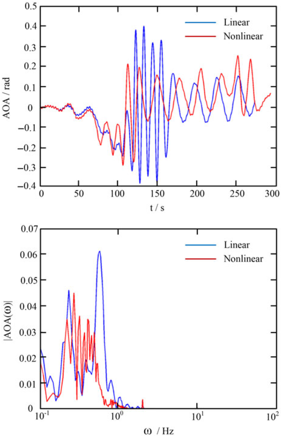
Figure 29. Time histories of the AOA response of a MAV airfoil to a non-uniform, unsteady incoming gusty flow using linear and nonlinear structural models(Reference Golubev, Dreyer, Hollenshade and Visbal175).
Besides the wing root bending effect, another important factor influenced by gust excitation is the wing twisting behaviour. Figure 30 shows the theoretical results of the tip chordwise RMS, midspan flapwise and tip twist amplitudes of a three-dimensional wing excited by a harmonic gust under zero- and two-deg steady angles of attack(Reference Tang and Dowell53). Overall, the gust response becomes more intense at the outboard positions and is largest at the tip. More specifically, as the chordwise excitation is dominated by the aerodynamic drag experienced by the wing and obviously is much larger at the steady angle of attack of 2 deg, the chordwise response becomes more than an order of magnitude higher than that at zero deg. For the midspan flap-wise response, due to the large static flapwise deflection(Reference Patil and Hodges82) there is a slight difference between the gust responses at the first and second flapwise natural frequencies (2.62Hz and 18.25Hz at which the first two peaks emerge, respectively). Although there is almost no significant difference between the two flapwise natural frequencies at zero- and two-deg steady angles of attack, yet there is an obvious difference in the frequency of the third peak (i.e., the first torsional natural frequency). This is because the torsional natural frequency is more dependent on the static flapwise deflection than the flap natural frequency and there is about a 0.002 m deviation between the two steady angles of attack at the torsional natural frequency. Such results are also observed in the bottom graph where the tip twist response near the torsional natural frequency has a significant variation with the steady angle of attack in both amplitude and frequency.

Figure 30. Responses of a 3-D wing to a harmonic gust at two angles of attack(Reference Tang and Dowell53).
4.3 Flight dynamics
One of the most common consequences of gust loading on aircraft is associated with the changed motion of an aircraft, which is directly caused by the affected aerodynamic performance and structural deformation, and in turn affects the two other aspects. The various consequences of gust loading to aircraft flight dynamics are discussed and analyzed below. It may happen that one parameter has different changes under different gust loading and flight conditions, thus necessary care should be taken if this case is encountered.
Dynamic gust response of aircraft in plunging and/or pitching (twisting) motions has been widely investigated experimentally and numerically. Figure 31 shows the wing bending moment coefficient and centre-of-gravity acceleration responses for a fighter-type aircraft at a cruise speed of Mach number of one to vertical sinusoidal gusts(Reference Gilman and Bennett48). The plunging and the short-period modes, which are respectively caused by the external pitch and vertical translation springs in the mount system and the wind tunnel turbulence, are adequate to observe at reduced frequencies of about 0.007 and 0.021, respectively. The first wing bending mode, whose concept is schematically illustrated in the last subsection, appears at a reduced frequency of about 0.15. Note that there is a notch in both curves at reduced frequency around 0.12, which is evidenced to be attribution of the occurrence of resonance between the test model and the mounting system(Reference Gilman and Bennett48).
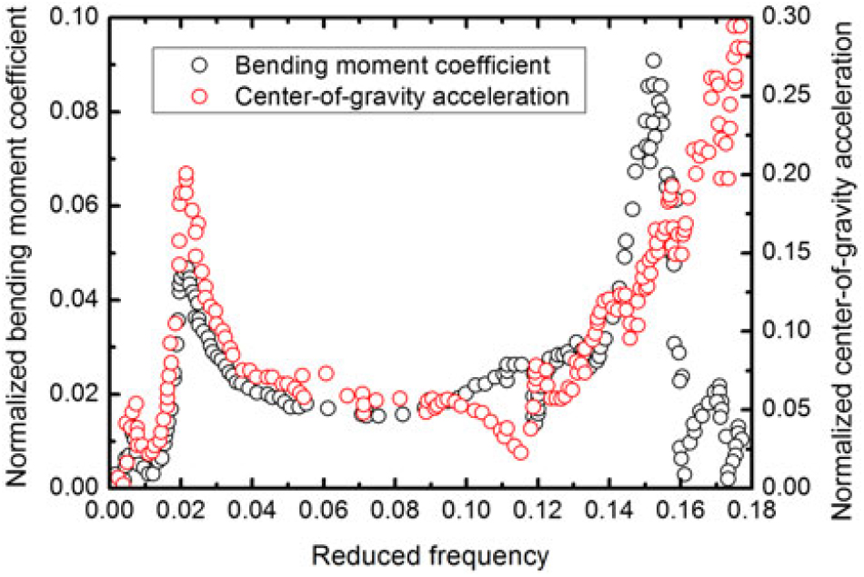
Figure 31. Wing bending moment coefficient and centre-of-gravity acceleration responses for a fighter to vertical sinusoidal gusts(Reference Gilman and Bennett48).
The abovementioned short-period mode and the first wing bending mode were also observed on the free-flight DC-10 transport aircraft(Reference Abel, Perry and Newsom60), as shown by the black curve in Fig. 32. The vertical axis represents the PSD function of the wing bending moment and the horizontal axis represents the dimensional frequency. In addition, two control laws patterned after the aerodynamic energy method and the optimal control theory respectively, were applied on the trailing-edge control surface to primarily increase the flutter speed of the aircraft. The results of the wing bending moment response are plotted by the red and blue curves in the same figure, respectively. It is observed that using both control laws on the control surface significantly decreases the first wing bending moment, but the second control law also leads to an undesired increase in the short-period bending moment. Although under the two control laws, the peak of the short-period bending moment is not not only due to the tunnel turbulence but also due to an Active-Control-System (ACS) filter mode at nearly the same frequency, yet the ACS filter of the second control law is almost an order of magnitude higher than that of the first control law. The test results indicate that the RMS value of bending moment is approximately reduced by one-third using the second control law, which is due to a drop in the area under the PSD between the short-period mode and first wing bending mode. However, the first law causes an increment of more than 50% in the RMS value of bending moment, which is due to a much larger increase in the area under the PSD surrounding the peak of the short-period mode.
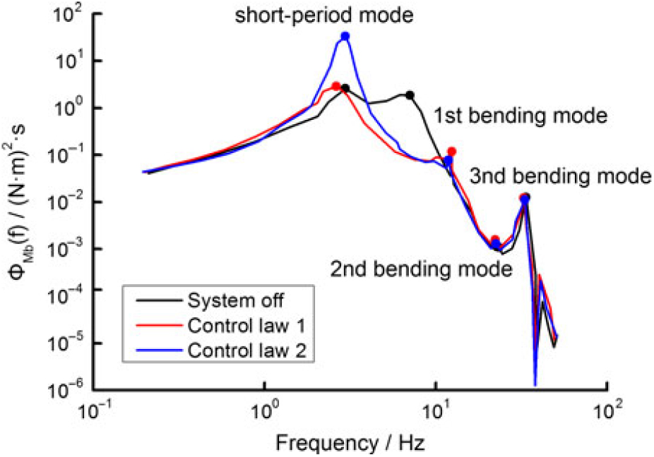
Figure 32. Bending modes observed on the free-flight DC-10 transport aircraft(Reference Abel, Perry and Newsom60).
Figure 33 shows the time-domain open-loop (i.e., without gust alleviation controls) and closed-loop (i.e., with gust alleviation controls) responses of the wing root bending and torsion moment of a Generic Transport Aircraft (GTA) excited by a one-minus-cosine gust(Reference Karpel, Moulin, Anguita, Maderuelo and Climent87). The control surface consists of two ailerons to alleviate the gust loads on the wing. It is observed that the control system reduces the wing root maximum bending moment by around 10% but slightly increases the wing root torsion moment. Meanwhile, the presence of the control surface smoothes the fluctuations in both moments during the gust encounter to some extent and makes the transport aircraft more stable and comfortable to passengers.
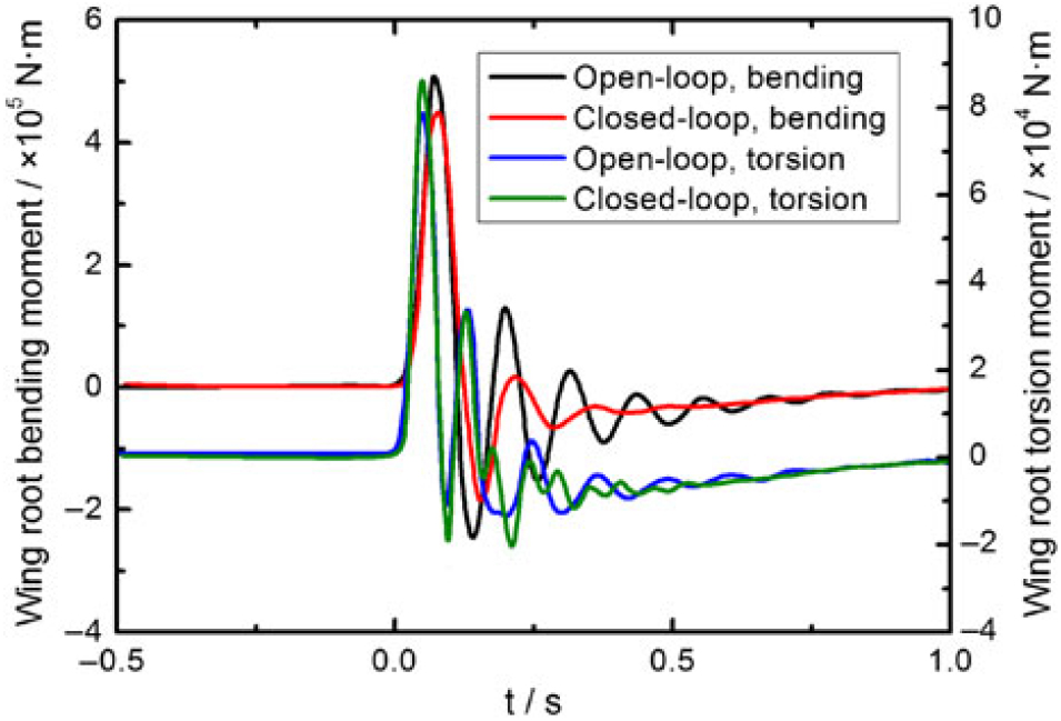
Figure 33. Comparison of the effects of gust alleviation controls on the responses of a GTA(Reference Karpel, Moulin, Anguita, Maderuelo and Climent87).
One group of the current authors, Cao et al. investigated the influence of wind shear on both helicopter flight characteristics(Reference Su, Cao and Yuan176,Reference Cao, Li and Sheridan177) . It was found that left wind, tail wind and downdraft decrease the longitudinal stability, while the left wind, right wind and downdraft decrease the lateral/directional stability, as shown in Fig. 34. These influences become stronger as the flight speed and wind velocity increase. Besides, the effect of head wind on the controllability of helicopter is stronger than that of tail wind.
Figure 34. Longitudinal and lateral/directional dynamic responses of UH-60A helicopter to winds at different directions(Reference Cao, Li and Sheridan177).
Figure 35 compares the trimmed responses of pitch angle θ, HTP deflection angle η, engine thrust and modal coordinate (i.e., displacement) of the first elastic eigenmode q1 of a free-flying flexible passenger aircraft under the GVB1 and GVB3 one-minus-cosine gust conditions(Reference Reimer, Ritter, Heinrich and Krüger122). The two conditions differ only in terms of flight speed. The former is subsonic (Mach number 0.450) and the latter is transonic (Mach number 0.836) while the gust properties of both cases are the same. It indicates flight regime is also critical to determine the gust responses besides the gust itself. Increasing the flight speed to about 1.86 times the baseline speed reduces the trimmed pitch angle to nearly 30% and the HTP deflection angle to slightly over 50% of the original values, while the trimmed modal coordinate increases nearly three times the baseline value. It seems that the results of the trimmed engine thrust are not affected by the different flight regimes, which implies that the drag forces are comparable in the two flight regimes.
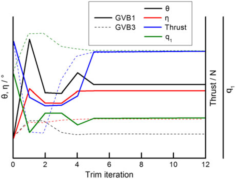
Figure 35. Trimmed responses of a free-flying flexible passenger aircraft under two one-minus-cosine gust conditions(Reference Reimer, Ritter, Heinrich and Krüger122).
Heinrich and Reimer(Reference Heinrich and Reimer103) incorporated the flight dynamics model into the CFD simulation of an A340-300 cruise configuration aircraft encountering a vertical sinusoidal gust, as shown in Fig. 36. When the gust is sufficiently far away, the aircraft flies horizontally with uniform speed. Thus, the pitch angle remains constant (point A). Afterwards, the gust starts to impose its impact on the aircraft in the same way as without considering the flight dynamics model. The effect of a vertical gust is equivalent to increase the angle-of-attack, resulting in an enhancement of the lift and upward bending of the wing, as well as a vertical force acting on the HTP, contributing to a ‘nose down’ pitching moment. Therefore, the pitch angle is reduced. The maximum effect arises when the centre of the gust reaches the aerodynamic centre of the wing (point B). After the gust has passed, the angle of attack begins to recover, resulting in an unloading at t ≈ 0.7 s. The second effect of the gust is that a “nose up” pitching moment starts to act and the pitch angle starts to increase. At about 1.4s, the initial value of the pitch angle is achieved. However, due to the effect of inertia, the pitch angle continues to reduce. The final stable status is reached at about 2s, when the gust is far away of the aircraft (point C). The behaviour of the pitch angle is similar to a damped oscillation, which is due to the nature of an intrinsically stable aircraft.
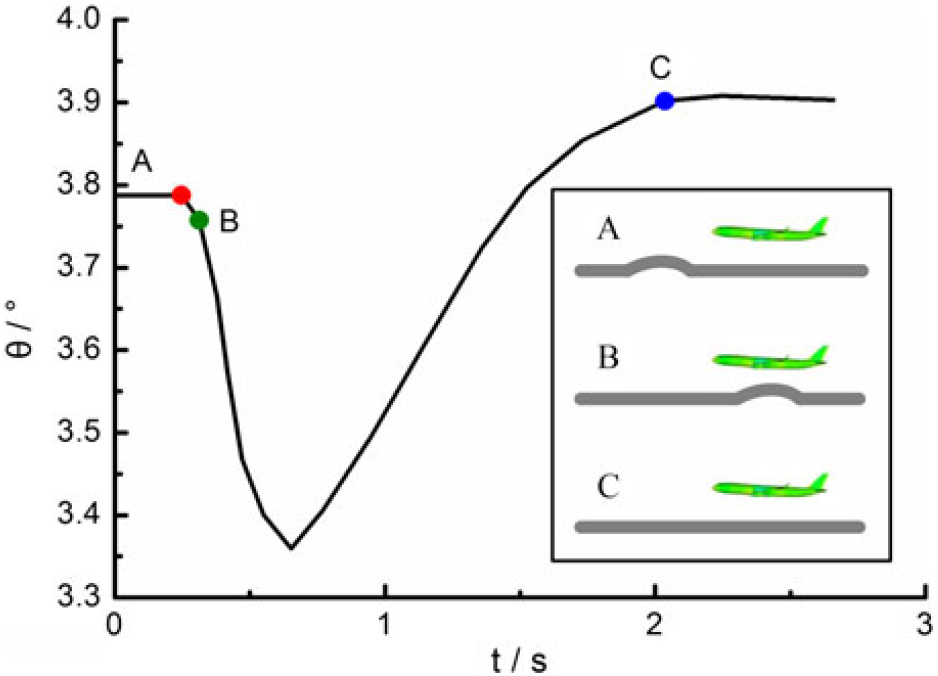
Figure 36. Time history of the pitch angle response for a passenger airplane to a vertical sinusoidal gust(Reference Heinrich and Reimer103).
A more intuitive scene of the gust influence on the aircraft flight path in the whole process of gust encounter is schematically shown in Fig. 37. Although both the initial position of the aircraft and the centre of the gust are fixed, yet due to the various gust durations the aircraft experiences, the aircraft performs obviously different positions and orientations when it gets rid of the gust effect (shown by the dashed line part). In addition, this deviation directly causes the difference in the aircraft position and orientation in its subsequent flight even after an appreciably long time of 20s. This requires people to specially focus the design of very light HALE aircraft and lighter-than-air vehicles such as aerostat and paraglider.
Figure 37. Flight path of the flying wing shown in Fig. 26 with different gust durations(Reference Su and Cesnik94).
5.0 GUST LOAD ALLEVIATION
As obvious from the last section, atmospheric gusts and turbulence adversely affect aircraft aerodynamic performance, structural lifetime, flight motion and thereof passenger comfort and flight safety. Gust load alleviation (GLA) has been one of the hottest subjects concerning gust and turbulence in the last few decades. So far, the main idea of GLA is to resort to aerodynamic control surfaces, whose motions are governed by certain control laws, in order to generate aerodynamic forces to modify the overall forces in a way that the gust response within the aircraft flight envelope is alleviated. In this section, a few principles and control strategies of GLA are depicted with some representative successful implementations.
5.1 Principle of GLA
When attempting GLA, basic principles with their related problems need to be discussed.
1) Alleviation intrinsically implies maintaining a constant load factor during a gust encounter. With respect to conventional aircraft excluding VTOL and STOL (Short Takeoff and Landing) aircraft performing take-off and landing, loads due to horizontal gusts can be neglected at low cruise lift coefficients. However, alleviating vertical gusts corresponds to keep a constant lift coefficient. Consequently, the slope of the lift curve is zero and the damping in pitch becomes lower.
2) Alleviation requires control surfaces to minimise other adverse effects on aircraft. For example, a very common way of manipulating the lift coefficient for vertical GLA is to use trailing-edge flaps. However, unfavorable pitching moment and downwash are also induced by the varying camber due to flap deflection. The downwash derivative with respect to angle of attack at the tail is significantly influenced. It may cause a sharp reduction in pitching stiffness and an amplified pitching response to gusts, which means a deteriorated stability of the aircraft. Meanwhile, increased camber also brings the issue of drag increase. Another stability issue associated with using the elevator for GLA is also presented(Reference Roesch and Harlan178). Other aspects, such as passenger comfort, payload to weight ratio, maneuverability and flight envelope, shall also be guaranteed as far as possible during GLA.
3) Simplify the program in the same condition of alleviation efficiency or enhance the alleviation efficiency as much as possible given the same design complexity. This rule seems to be self-evident, however, it is very important to aircraft with so many degrees of freedom and states involved(Reference Dillsaver, Cesnik and Kolmanovsky179). Another consideration is that there are inevitable time lags in the response of control surfaces to the control commands, thus affecting the alleviation efficiency and effectiveness. Generally, simpler the control strategy, easier to implement and more timely and accurate the control surface responses.
4) Last but not the least, there is no single best GLA technique. A suitable one is made through an overall and synthetic consideration of the performance requirements, feasible control means, precision of the mathematical model, measurement accuracy and present computer capacity, etc. Therefore, choosing a suitable GLA control program is an optimisation not only of the internal control parameters but also of all other external considerations involved.
5.2 Alleviation strategy
In the past few decades, extensive research has been carried out to develop GLA systems for controlling aircraft aeroelastic response to gusts and turbulence. In general, these systems can be broadly classified into two categories, passive and active controls. The most important difference between both control strategies lies in the idea of using solely the natural forces or with external forces and energies as well.
5.2.1 Concept
1) Passive control
Passive control is a traditional strategy based on the idea of structural modifications usually associated with weight penalty, such as mass balance and stiffness tuning. In the process of passive controls, the control surfaces are inherently dominated by the aerodynamic and structural forces they are naturally subjected to. This passive control strategy can be applied not only to GLA, but also to Maneuver Load Alleviation (MLA)(Reference Lewis180) and flutter suppression(Reference Karpel181).
A typical example of passive control is shown in Fig. 38. A separate wing segment is mounted at the wingtip through a shaft and torque spring connected to the wing front spar, which is called passive twist wingtip (PTWT). The shaft is located in front of the aerodynamic centre so that the gust-induced aerodynamic force causes a nose-down motion of the PTWT, which produces a negative aerodynamic force on the PTWT leading to an alleviation of the gust loads on the whole wing. Analyses proved that using this control strategy, the gust-induced responses of the baseline wing are overall decreased. It further causes wingtip deflection, bending moment, rolling moment, roll rate, roll angle, roll acceleration reduced by 21.2, 10.6, 20.5, 11.6, 10.6, and 13%, respectively. In the past when the calculation tools and sensor technologies were not so strong as nowadays, this control strategy was a very popular, practical option for unfavorable load alleviations.
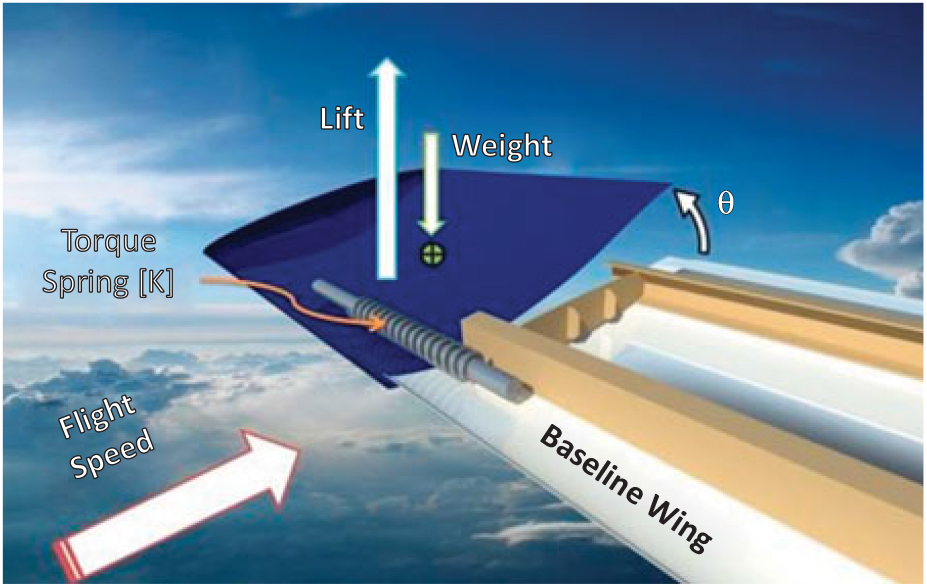
Figure 38. The passive twist wingtip for gust alleviation(Reference Guo, Los Monteros, Espinosa and Liu182).
2) Active control
Active control is an advanced modern strategy where the design concept is totally different from passive control. In active control systems, only aerodynamic control surfaces belonging to the aircraft itself, such as flaps and ailerons, are used to generate aerodynamic forces modifying the overall forces with gusts according to a control law relating motions of the control surfaces according to the measurements made on the aircraft(Reference Regan and Jutte183). In this process, external forces and energies are usually resorted to actively operate these control surfaces.
A representative active control means is illustrated in Fig. 39. The aircraft angle of attack (α) is sensed for gust signal computation along with the other aircraft motion parameters including pitch angle (θ), pitch rate (q) and vertical acceleration (az). Afterwards, gust loads are computed and fedback to the servo actuators to drive the flaps of the wing and the elevators to deflect by δ in a manner counteractive of the gust-induced angle of attack response. Simultaneously, the extra pitching moment and downwash due to the motion of the flaps are also fed back and compensated by the elevators to keep the aircraft balanced.

Figure 39. Illustration of a representative active control measure.
5.2.2 Pros and cons
Passive controls can be more practical than active means in many instances where adding mass and stiffness tuning(Reference Arrieta, Bilgen, Friswell and Hagedorn184) or a simple auxiliary(Reference Roesch and Harlan178) to the vehicle can obtain a good consequence of load alleviation. However, this advantage also has certain drawbacks as these practices often bring extra mass to the vehicles. Another drawback of passive controls is that it is often hard for them to meet the need of mitigating gust loads in the entire flight envelope. In practice, usually the worst gust cases are considered.
Because active controls often resort to aircraft’s autologous control surfaces plus proper control laws, external forces and energies are needed to bate adverse gust loads on aircraft without significant mass penalty to aircraft. Therefore, active control strategy is more extensively employed in GLA researches and practices than passive control. However, with the increasing emphasis on fuel efficiency and payload to structural weight ratio, more complex control laws for active GLA, such as feedforward control(Reference Hahn and Schwarz185,Reference Zeng, Moulin, De Callafon and Brenner186) and feedback control(Reference Block and Strganac187,Reference Wildschek, Maier, Hromcik, Hanis, Schirrer, Kozek, Westermayer and Hemedi188) , are needed, as there are inevitable time lags in the development of responses of control surfaces to external commands.
5.3 Existing applications
The main factors affecting gust loads are direct loads due to gusts, airplane motion due to gusts or controls and action of special control to offset gust loads(Reference Phillips189). Direct loads due to gusts are proportional to the lift-curve slope, dynamic pressure and change in angle of attack. Aerodynamic devices reducing the lift-curve slope include the use of sweep or reduced aspect ratio by applying chordwise slots and spoiler-deflector control. The airplane motion is dependent on the basic airplane stability, autopilot and manual operations. The action of special controls includes the alleviating effects due to wing bending, the use of hinged surfaces, and special GLA controls such as wing flaps operated by servo systems. Generally, developing GLA strategies can be accomplished by the variation of the above mentioned factors.
In the following, some representative practices for gust alleviation are presented for the four aspects. The moment the people realised the severity of gust loads, there have been a large number of inventions for the purpose of gust alleviation. The goal of our study here is to help the reader to obtain a clear picture regarding the development of gust alleviation measures.
5.3.1 Flight tests
Flight tests of GLA systems can be dated back to the middle of the last century. In 1956, Cooney and Schott proposed a synthetic control system alleviating airplane motions in gusty conditions(Reference Cooney and Schott190). The control system included trailing-edge flaps and ailerons changing the gust-induced angle-of-attack sensed by a vane, as well as a split elevator whose outboard parts were geared to the flaps to balance the auxiliary pitching moment as already described in Subsection 5.1. Their flight tests indicate that using this gust alleviation system, a reduction of 43% in the RMS normal acceleration at the airplane centre of gravity was achieved. In 1973, the Air Force Flight Dynamics Laboratory (AFFDL) and the Wichita Division of The Boeing Company jointly conducted a series of flight tests on a Ride Control System (RCS) on a B-52(Reference Mckenzie191). Results indicate that the system has a higher damping versus airspeed, which is potentially able to alleviate gust loads on aircraft. Later the AFFDL also tested the Control Configured Vehicle (CCV) system on the YF-16 aircraft. In 1977, Disney(Reference Disney192) conducted flight tests to examine the capacity of a control system with ailerons and inboard elevator for GLA. Results indicated that with the existing lateral and pitch stability augmentation system on, the wing root bending moment response can be reduced by 30%-50%. The DLR (German Aerospace Center) designed the Load Alleviation and Ride Smoothing System (LARS) for GLA and conducted a series of studies via flight test on a model aircraft since the 1990s(Reference Hahn and Koenig193). Results showed that the LARS can only reduce the gust-induced lift in the normal direction but neglected the horizontal accelerations.
5.3.2 Wind-tunnel experiments
Since the early age of research on gust loads on aircraft, there have been many attempts of alleviating gust loads in gust tunnels. In 1941, Shufflebarger tested the effectiveness of a torsionally flexible wing to mitigate gust loads in the NACA gust tunnel(Reference Shufflebarger194). The results indicate a maximum reduction of about 17% in the maximum acceleration for the gust shapes of interest. Later, the same group designed a gust alleviation system with forward-located fixed spoilers, deflectors or their combination for a transport airplane model(Reference Croom, Shufflebarger and Huffman195).
In 1976 and 1978, Stewart and Doggett(Reference Stewart172,Reference Stewart and Doggett196) conducted tests of a passive aeromechanical gust alleviation system for reducing the normal acceleration response of light airplanes in the NASA Langley Research Center. Two auxiliary aerodynamic control surfaces were mounted on the fuselage below the wing to drive the wing flap in order to counteract the gust-induced lift force and maintain a constant overall lift on the wing. Results indicated that a reduction of 30% in the RMS normal acceleration response and a slight pitching rate response were obtained with the activation of the control system. In 2007, Moulin and Karpel(Reference Moulin and Karpel173) tested three different control surfaces, the Basic Main Ailerons (BMA), an Under Wing Control (UWC) surface and a Wing Tip Control (WTC) surface to examine their ability of alleviating gust loads on a transport aircraft. Results indicated that the three control laws reduced the maximal bending moment by 9.4, 13.3, and 15.1%, respectively, in contrast to the BMA open-loop case. The EU funded project GLAMOUR tackles the development, implementation and experimental verification of GLA technologies applied to a Green Regional Aircraft(Reference Ricci, Adden, Servadio, Karpel and Cooper174,Reference Ricci, De Gaspari, Riccobene and Fonte197,Reference De Gaspari, Mannarino and Mantegazza198) . Wind-tunnel experiments have been performed to validate the strategies using motors, ailerons and elevator actuators in Refs Reference De Gaspari, Mannarino and Mantegazza198 and Reference Fonte, Ricci and Mantegazza199.
5.3.3 Analytical investigations
In 1963, Zbro˙zek(Reference Zbrożek200) analyzed a gust alleviator equipped on the Lancaster ME.540(Reference Council, Zbrozek, Smith and White201) using the spectral technique. He observed that the estimated loss of alleviator effectiveness closely agreed with the experimental observations. In 1970, Porter and Brown(Reference Porter and Brown202) analytically evaluated the gust-resisting characteristics of a free-wing aircraft in the subsonic flight regime. The main difference between a conventional aircraft and the free-wing aircraft is that the wings are free to move independently about a spanwise axis controlled by trailing-edge control tabs. It was found that the free-wing concept has natural gust-alleviation characteristics. The most dramatic reductions lied in normal load factor increment, vertical path displacement and roll disturbance. In 1971, Nissim proposed the concept of aerodynamic energy which was used with active controls for flutter suppression(Reference Nissim203) and later extended this method for GLA(Reference Nissim, Caspi and Lottati204,Reference Nissim205) . Using a control law based on the aerodynamic energy concept, an active control containing strips on the 20% chord leading and trailing edges was validated to be able to eliminate the bending moment due to gust loadings totally (application of the aerodynamic energy concept to flutter suppression and gust alleviation by use of active controls). In 1974, Lullman investigated different methods of alleviating the response of a STOL transport to gusts using the elevator, spoilers and trailing-edge flaps as control surfaces(Reference Lullman206). Results show that feedback control using the elevator decreased the aircraft overall response to gusts. Inclusion of the spoilers in the feedback control decreased the normal acceleration and flight path angle responses to gusts, while the trailing-edge flaps reduced the low-frequency pitch angle and speed responses to horizontal gusts. Oehman(Reference Oehman207) also showed that a combined control system with the wing trailing-edge flaps and the elevator can reduce the RMS normal acceleration of a STOL aircraft in random turbulence by 50%. In 1977, Amos(Reference Amos and Alexander208) identified preliminary design parameters of a flap-elevator GLA system and evaluated its performance for the XV-15 tilt rotor aircraft. The results indicated that the control system can produce gust alleviation factors up to 70% with no obvious adverse effect on blade loads or hub moments.
Many newer methods have emerged since the 1990s, such as neural network(Reference Gili and Ruotolo209–Reference Cavagna, Ricci and Riccobene211), Linear Quadratic Regulator (LQR)(Reference Nam, Kim and Layton212), Linear Quadratic Gaussian (LQG)(Reference Dillsaver, Cesnik and Kolmanovsky179,Reference Vipperman, Clark, Conner and Dowell213) , robust (H2/H∞)(Reference Ozbay214,Reference Aouf, Boulet and Botez215) , etc. Besides, the advanced aerodynamic configurations in flight vehicle design require more complex and multidisciplinary control strategies(Reference Hahn and Koenig193,Reference Britt, Jacobson and Arthurs216) . Those methods and studies have led the trend of gust alleviation for the next century.
Since the beginning of the 21st century, novel control laws and methods have been utilised successfully for GLA. Xu, et al.(Reference Xiaoping, Xiaoping, Zhou and Ruijun217) applied active flow control techniques of blow, suction and synthetic jet airflow to alleviate gust loads for the quasi “Global Hawk” airfoil. Their CFD numerical results indicate that using this new active flow control strategy, the amplitude of the lift could be reduced by 17.67% with the steady blowing method. Chen, et al.(Reference Chen, Wang and Li218) proposed a gust alleviation control law design method based Proper Orthogonal Decomposition (POD)/ROM for flexible aircraft in the transonic flow regime. Using this method, they showed that the gust-induced lift and moment can be reduced by more than 50% for both the discrete 1-minus-cosine gust and a sequence of 1-minus-cosine and sine gust. Cook and Palacios(Reference Cook, Palacios and Goulart219) proved that an H8 controller performs well on a relatively large linearised system with 9% alleviation in root bending moment under the specified gust condition. Wang and Inman(Reference Wang and Inman220) tactfully associated energy harvesting and gust load alleviation simultaneously using Reduced Energy Control (REC) laws for a composite wing spar for a small UAV. The amplitude of the RMS tip displacement is dramatically reduced from 4.5 mm to 1.0 mm, exhibiting high gust alleviation efficacy for future practical applications. Cao et al. proposed a low-altitude wind shear penetration flight control law using the Nonlinear Inverse Dynamics (NID) method(Reference Cao, Chen, Yuan and Jin221,Reference Cao and Yuan222) . The calculation results of an Airbus 300 aircraft indicated that the NID control logic works effectively in the aircraft trajectory control during the penetration of wind shear. Fonte, et al.(Reference Fonte, Ricci and Mantegazza199) designed a symmetric, active GLA system for a regional transport aircraft based on a static output feedback (SOF) with a constrained structure. The control surfaces of two ailerons and the elevator were taken into consideration. Using the control strategy, the variance of the wing root bending moment caused by gust was maximally reduced by more than one-third compared to the open-loop condition (see Fig. 16 in Ref. Reference Fonte, Ricci and Mantegazza199).
5.3.4 Patents
The earliest patent for gust alleviation might be the one in 1952(Reference George223). Described generally, gust alleviation is realised by mounting the main wing assembly to swing bodily up and down to compensate automatically the aerodynamic attitude of the wing structure influenced by gust encounters. Cannon and Johnson(Reference Atwood, Cannon, Johnson and Andrew224) contemplated the usage of a plurality of null servos of extremely fast response. This can get the real-time information of the actual response of the aircraft to a gust that the time lags in the motion of control surfaces and secondary changes in the aircraft flight conditions due to imperfect alleviation of a primary gust for the previous gust alleviation systems are circumvented. In 1980, Tefft, et al. utilised the pitch and roll channels of the stability augmentation system to reduce the effects of gusts on the helicopter attitude at low forward speeds (below 60 knots). Beside this usage, the lightspots of the invention also causes reduction of pilot work during hover and cruise and improved aircraft stability during hover and in gusty conditions(Reference Tefft, Perez and Barnum225). Ham(Reference Ham226) also proposed a novel active control system called Individual Blade Control (IBC) for helicopter gust alleviation. In this, the blade pitch was controlled by means of broadband electrohydraulic actuators attached to the swash plate or individually to each blade. This practice showed multiple advantages over the previous controls, such as gust alleviation, attitude stabilisation, vibration alleviation and air/ground resonance suppression. In 1990, Chin designed a system combining the gust alleviation system with the existing G-command flight control system, which can minimise the interaction between the two systems(Reference Chin227). In 2004, Hassan, et al.(Reference Hassan, Hamilton and Ngo228) invented an active control device comprising an array of oscillating air jets that can be disposed on numerous aircraft structures, including rotor blades, wings, engine inlets and exhausts. Initial unsteady disturbance signals such as gusts and wakes are input into a processor which generates output signals to operate the air jet array in a manner counteractive to the disturbances.
5.3.5 Application examples
This subsection selects some opened examples with GLA controls, which have been successfully implemented in practical applications, as illustrated in Table 1.
Table 1 Summary of some operational aircraft with documented control systems to alleviate gust response
6.0 SUMMARY AND CONCLUSIONS
Atmospheric gust has been considered as a major threat to aircraft flight performance and safety for centuries. Therefore, it is an ongoing important research subject in the aeronautical community. In reality, random atmospheric gusts and turbulence can cause a lot of troubles, threats and even accidents to aircraft. Even there has been great progress in forecasting and alleviating gust loads on aircraft, and the incidence of many problems and accidents that were commonly caused by gusts do have significantly reduced nowadays, gust response analysis and evaluation is still an essential step in modern flight vehicle design. As the global development of passenger airplane is flourishing, advanced gust investigation methods and design criteria are desired. This review presents a systematic description and discussion of the current state-of-the-art research in the field of gust loads on aircraft. Total ten parts have been made and logically arranged to identify the latest research achievements regarding gust loads on aircraft, as indicated in the catalog of this paper. The primary intent of this review is to give the reader a chance to obtain a comprehensive knowledge of the adverse effects of atmospheric gusts on aircraft and to enlighten new ideas and approaches for later-generation gust research.
Similar to the more generic aeroelastics problem, gust research techniques can be broadly divided into three categories, analytical modeling, experimental measurement and CFD numerical simulation. The most costly and dangerous approach is experimental approaches particularly flight test. Therefore, an alternative or a combination of the other two categories of gust approach is preferred, especially in the phase of aircraft primary design. For a general CFD solution of an aeroelastics issue, the most challenging question is associated with the realisation of mesh deformation in the process of calculation. An alternative is by using prescribed velocity methods, which have now been widely employed to simulate grid motions without actually distorting the mesh, thus largely reducing the computational cost. A more common, effective and efficient practice is the generic CFD-based ROM approach, which solves the system’s Euler/NS equations for generalised aerodynamics and/or aeroelastic equations of motion for both aerodynamics and structural dynamics with system order reductions.
The models have evolved for design and certification of gust loads over the years, which include the following categories: discrete gust model (both for static and dynamic), statistical discrete gust model and continuous gust model. Although simple and ideal, the discrete gust models are still the most widely used models in both academic explorations, engineering designs and airworthiness certifications. Although the continuous gust load approach offers a more robust and realistic representation of the atmosphere, yet it has not superseded the discrete-gust approach in the practical design and certification. Flight data recorders have indicated that larger gusts often exist as discrete ones and the discrete gust approach is more suitable for predicting discrete gust load effects. Given these factors, both the discrete gust and continuous gust load models are presently required by the mainstream air regulations in the world.
Subsequently, this paper presents a brief introduction of the primary gust research approaches, including experimental measurement, analytical modeling, full-order CFD numerical simulation and reduced order modeling. Aeroelastic phenomena are classified into either static or dynamic. In the early time, aeroelastic problems were treated as static, as the structural issues such as deformation and fatigue were not a main focus at that time. However, with the large advances in material science, aircraft structure has become more and more flexible and smart. The unsteady nature of the aerodynamic forces and moments generated when the aircraft oscillates as well as the effect the motion has on the resulting forces have more and more been required to treat as dynamic aeroelasticity. The presence of flexible modes influences the dynamic stability modes of the rigid aircraft and so affects the flight dynamics. Also of serious concern is the potential unfavorable interaction of the flight control system (FCS) with the flexible aircraft, known as structural coupling or aeroservoelasticity. Gust modeling theories considering these factors are crucial and need to be updated.
One of the most important parts is the fourth section of the review, which elaborates the various aspects of gust impacts on aircraft, as summarised as follows.
(1) Aerodynamics
• In general, gusts can heavily increase the aerodynamic loads on aircraft compared to the mean no-gust inflow conditions. However, the strength of this impact varies dominantly for different gust conditions. For example, for an individual gust, the lift becomes stronger with the increasing gust wavelength, non-uniformity, forwarding speed. For general turbulence, as the turbulence intensity increases, the drag can be increased while the lift can be decreased.
• Presence of gust can significantly alter the flowfield characteristics of aircraft, resulting in complex aerodynamic interactions with the aircraft such as disturbance propagation and wake deflection.
• In addition that the gust or turbulence itself determines the aircraft aerodynamic performance, aircraft own properties also play an important role, such as the structural elasticity, weight, scale and type (including the configuration) of the aircraft.
(2) Structural dynamics
• Like LCO and flutter, gusts can also generate significant vibrations inducing various aircraft elastic modes, such as multiple wing bending and torsion and engine yaw and pitch. Main affecting factors are the characteristics of gusts, the properties and flight conditions of the aircraft. For example, longer gust duration and higher gust amplitude generally induce more severe structural deformations. Lower mass ratio motivates the plunging and pitching responses while large stiffness suppresses these responses. Higher angle of attack may considerably enlarge tip bending amplitude whereas it reduces the tip twist amplitude.
• Aircraft configuration is a most important dominating factor of gust-induced structural response. Highly flexible HALE aircraft, tiny and light MAVs and NAVs belong to the largest community subject to adverse gust impacts.
(3) Flight dynamics
• Aircraft flight dynamic performance is also dominated by the gust parameters, aircraft flight conditions, and aircraft’s configuration, which is directly caused by the already affected aerodynamic performance and structural deformation. However, in turn the subjected flight dynamics also affects the two other aspects.
• Different control laws can bring completely different effects while tackling gust loads on aircraft. An improper application of control laws can even increase the destructiveness of gusts.
• For highly flexible aircraft, gust loads overall affect the aircraft stability characteristics, regardless of longitudinal, lateral or yawing. These include increased amplitudes of the flight altitude and pitch angle but decreased mean altitude with the increasing gust duration and velocity amplitude. This may also apply to some unconventional aircraft such as joined wing. However, for less flexible conventional aircraft, the adverse gust effects on flight stability can almost be eliminated.
• Gusts effects begin to act in advance of the aircraft’s encounter and last sometime even when the gust is located far away from the aircraft. This result is particularly important to flight dynamic performance of very flexible and light aircraft.
Of course, regarding the rich achievements in the investigation of adverse effects of gust loads on aircraft, the core and ultimate object should be oriented to the alleviation of gust loads. The last important part of this review concerns with the current state-of-the-art theories and practices in the field of GLA. Control effectors include auxiliary control surfaces for passive control, as well as conventional control surfaces for active control. Although some control practices have shown a strong ability of fully eliminating the gust loads, yet no single control methodology or technique has proved superiour and almighty for all kinds of gust forms. In addition, many studies have also suggested that certain control designs originally intended for other purposes, e.g., flutter suppression, can indirectly help mitigating gust loads and improve ride qualities. Likewise, some controls originally used for GLA can also bring significant improvement on aircraft performance, such as stability enhancement and air/ground resonance suppression.
7.0 FUTURE WORK
Much still can be done in the future, for example,
• Research in the atmosphere itself is costly and proceeds slowly, as the properties of atmospheric gusts and turbulence vary considerably at different altitudes. We can only expect to see a continuation of flight research on the properties of gust and turbulence at all altitudes to refine the statics of occurrence and to probe more deeply into its structure. For flight test of gust response and load alleviation, previous flight recording data also shows that pilot control actions can have a significant effect on the loads experienced during flight through moderate or severe gusts. Therefore, it is necessary to take the effects of pilot’s dynamic control manipulations into consideration when measuring gust load itself and the aircraft response to the gust. In addition, a wider range of aircraft mass cases with different fuel loading and centre of gravity positions has to be tested. Gust sensors and control surface actuators should be coordinated to manipulate both rigid body and flexible modes that are observed simultaneously, without unfavourably exciting or aggravating other modes.
• For wind-tunnel experiment, refined gust generators, new technologies such as transition and separation point detecting and ranging, and more advanced instruments for identifying favourable turbulence from tunnel-wall generated turbulence need to be developed. Additional aircraft configurations should also be tested for comparison. There are still large gaps in our knowledge of understanding of the physical mechanisms responsible for severe gusts. The realisation that severe gusts are not just larger versions of the more common less severe ones, but may differ from them in kind as well as in degree, implies that measurements must be made of the severe gusts themselves. This increases the difficulties and of experimental work.
• Although experimental techniques have been relatively mature nowadays, yet there is still much potential of theoretical prediction of gust loads using full CFD numerical simulation and CFD-based ROM simulation. The simulation environment allows more clarity on parameters significantly influencing the dynamics of aircraft, such as lift and drag coefficients, compared with experimentation. Trends are being changed from traditional RANS to URANS, DES, LES, and their combinations. As the science and technology of computer are advancing fast, DNS (direct numerical simulation) of gust response of 2-D airfoils, 3-D wings and even full aircraft can also be expected in the future. On the other hand, most of the state-of-the-art ROMs are linear or low-order. Research is underway to develop methods for synthesising nonlinear high-order ROMs in state-space form using various approach. More experimental data on severe gusts, as well as theoretical interpretation, is needed before a physically valid model can be put forward for use in design. Besides, more work needs to be done on the theoretical prediction methods associating with control design algorithms and flight mechanics models incorporated. Good progress is, however, being made towards this end.
• There is also a need of rapid progress in development of theoretical models and estimation techniques. The current use of gust statistics, such as the spectral density, which describe averages in order to predict extreme values for design cases a questionable procedure unless adequate attention is paid to other probability properties. More and more evidences have indicated that these properties are not Gaussian. Work on theoretical models of extreme gusts which are more physically plausible than those used in the past is presenting good progress and leading to more rational design criteria. In addition, additional states and more precise measurement models for wind velocity should be included in the state-space equations of motion. On the other hand, more accurate representation of the unsteady aerodynamic loads is needed. This has at least twofold considerations. One is the more precise prediction of gust response characteristics, as currently aerodynamic approximations are commonly applied in the modeling of gust-induced aerodynamic forces. The other is associated with the fact that the main difficulty in modeling of an aeroelastic system for GLA control analysis lies in the representation of the unsteady aerodynamic loads. Because of the time lag in the development of these loads, non-rational terms are inevitably contained in the analytical expressions. Third, more elaborate structural models and approaches can also be developed in the event of large wing deflection expected for HALE aircraft.
• As aircraft structure is becoming more efficient and the separation between rigid-body and flexible modes is reducing. New challenges are emerging for controlling more flexible, light-weight aircraft in atmospheric gusts and turbulence. Considering that both the passive control and active control strategies have inevitable imperfections, a strategy of combining both passive and active controls is a more advisable practice. Although some attempts have been made and obvious gust alleviation effects have been shown in the past, yet more work in greater depth is required for joint control strategies. Perfect gust alleviation is certainly impossible, not only because of limitations on sensing and actuating devices, but also because of the inherence in flexible vehicles that alleviation designed to reduce motion of stress in one part of the aircraft will inevitably increase it somewhere else. In addition, the flight test method has been less utilised for GLA explorations since the 21st century. The future trend of GLA research shall be led by designing advanced sensors, effectors and control laws under the combined efforts of analytical evaluation and wind-tunnel validation.
• The thunderstorm is still the greatest hazard. Further improvements in gust aspects of weather forecasting seem likely in the future, considering progress has been made in understanding of the physical mechanisms of the interactions between gusts and aircraft. In addition, more efforts in crew training in the use of airborne weather radar for avoidance storm as well as other severe gusts has to be made in the future. Although it seems that no great improvements in the radar itself can be foreseen, improvements in the display of information to the pilot are possible. It is convincing that, airborne radar alone, in at least some areas, is not enough, and a good weather display to the air traffic controller is also necessary.
Overall, research on gust loads on aircraft involves a comprehensive multidisciplinary issue, which goes across several main topics, such as aerodynamics and aeroelasticity, structural and flight dynamics, turbulence, optimisation and control, etc. Therefore, more interdisciplinary and inter-organisational communication and cooperation will be crucial.
ACKNOWLEDGEMENTS
This work was supported by the Alexander von Humboldt Foundation (grant No. 1190117) and the Fundamental Research Funds for the Central Universities (grant No. YWF-19-BJ-J-204). The first author would like to thank all the members of Institute of Aerodynamics and Gas Dynamics (IAG) of University of Stuttgart, especially Prof. Krämer, Dr. Lutz, Mr. Müller, for their precious help in academic guidance and administrative affairs.


 Open access