


Introduction
Circularly polarized (CP) microstrip patch antennas are employed in a wide range of applications such as sensing, wireless communication, and radars due to their low-profile structure. CP patch antennas have several advantages such as reduction in polarization mismatch, immunity to distortions, and interferences. Because of the narrow bandwidth of CP microstrip patch antennas, it is very difficult to maintain a balance between wide impedance bandwidth (IBW) and the low-profile nature of antennas. In the past, some conventional methods such as stacked patches, capacitive coupling feed, parasitic resonators, thick substrates, and reactive slot-loading are employed to improve antenna operating bandwidth [Reference Wong1–Reference Yang, Zhou, Yu and Li3]. In all these techniques, axial ratio bandwidth (ARBW) is improved but these methods either increase the profile of antenna or increase the complexity in designing the antenna.
One of the good methods to improve the IBW of microstrip patch antennas is employment of metasurfaces (MTS) [Reference Chung and Chaimool4, Reference Caloz and Itoh5]. Many MTS-based methods are used to improve the bandwidth of patch antennas [Reference Zhu, Chung, Sun, Cheung and Yuk6–Reference Gao, Cao, Gao, Yang and Han17]. These techniques include designing of MTS using effective medium theory (ɛ-μ) [Reference Chung and Chaimool4, Reference Zhu, Chung, Sun, Cheung and Yuk6], reflection/transmission coefficients (Sij) [Reference Konstantinidis, Feresidis and Hall7, Reference Chen, Yang, Feng, Zhu, Zhao and Jiang8], equivalent circuit model (R-L-C) [Reference Al-Joumayly and Behdad9], composite right/left-handed transmission lines [Reference Wang, Dong and Itoh10], and surface impedance extraction [Reference Pandi, Balanis and Birtcher11, Reference Pfeiffer and Grbic12]. However, these methods are not able to give proper solutions to the radiation issues of antenna, where MTS consists of few numbers of unit cells closely attached with the primary radiating source. The prominent issues are the approximation of infinite periodic boundary conditions and calculation of excitation modes. Then, a single-layer MTS-based wideband CP antenna is designed for high gain. The proposed antenna is low profile in nature with the dimensions of 1.18λ 0 × 1.18λ 0 × 0.05λ 0 and an IBW of 14.7% [Reference Hussain, Tran and Le13].
Further, characteristic mode analysis (CMA) is successfully used for the design of low-profile MTS-based antennas. CMA technique provides modal behavior of the structure and physical insight in the current pattern of the structure, which greatly helps in improving the radiation pattern of these antennas and also improves the aperture sharing in the antennas [Reference Pandi, Balanis and Birtcher11, Reference Pfeiffer and Grbic12, Reference Han and Dou14]. However, additional modes in the MTS can be excited to achieve the wideband in MTS-based antennas. Further, an MTS-based CP antenna with low in-band radar cross-section (RCS) is proposed. CMA is applied on a rectangular patch-based MTS to achieve 3 dB ARBW of 9.05% and an IBW of 29.41%. The proposed design achieves a broadside gain of 6.34 dB [Reference Rajanna, Rudramuni and Kandasamy15]. Recently, CMA technique is employed to design an MTS-based dual-polarized array antenna for 5 G millimeter-wave applications. The designed antenna realized dual IBWs in the range of 24.2–27.8 GHz and 36.9–42.8 GHz [Reference Feng, He, Cheng and Sim16]. Then, a wideband low-profile high-gain antenna is proposed using CMA. In the proposed design, characteristics modes (CM) are excited to achieve wideband operation. The working bandwidth of the designed structure is 5.3–7.94 GHz with a peak gain of 10 dBi [Reference Gao, Cao, Gao, Yang and Han17]. Recently, a miniaturized reconfigurable tri-polarization MTS antenna is proposed using CMA. The proposed design uses PIN diodes for polarization switching and an IBW of 24.6 for CP and 24.1% for linear polarization with a peak gain of 5.25 dBic [Reference Huang and Wen18]. It is clear that circular polarization and gain enhancement can be achieved with the help of MTS designed using CMA. However, achieving wideband circular polarization with high and stable gain is still a difficult task, but with the help of CMA technique, these tasks can be achieved while maintaining the low-profile nature of the antenna.
In this work, a wideband CP low-profile MTS-based antenna with out-of-band scattering suppression is presented. The circular patch-based MTS layer is first analyzed by employing CMA without ground, then a slotted ground is introduced and CMs of the structure are analyzed for gain enhancement and circular polarization. It is noticed that modes 2 and 3 with comparable magnitude, broadside radiation, and orthogonal current directions can be used for achieving circular polarization. So, a proper coplanar waveguide (CPW) feeding system is implemented to perfectly excite these modes to obtain broader operating frequency band and 3 dB axial ratio band. The unique features of the designed MTS-based antenna are: (1) miniaturized dimensions of antenna are 0.67λ 0 × 0.67λ 0 × 0.040λ 0, (2) UWB IBW of 96.93%, (3) 3 dB ARBW of 41.8%, (4) low profile and measured maximum gain of 7.9 dBic at 7.97 GHz, and (5) wideband scattering suppression in the frequency range of 10–24 GHz. This proposed work is arranged as follows: section “Characteristics mode theory” includes discussion on CMT. In section “Evolution of wideband CP antenna using CMA,” the CMA approach for circular-shaped MTS structure is discussed. This section is divided into three subsections where in the first subsection, CMA is applied over MTS layer. In the second subsection, CMA is applied over MTS layer with the slotted ground, and in the third subsection, CMA is applied over MTS layer with the modified slotted ground. Section “Antenna design” includes the antenna design in which the slot is converted into CPW feed. Section “Antenna design” includes the result and discussion, which has a detailed comparison between measured and simulated results. Section “Conclusion” concludes the work and derives the conclusion of the proposed work.
Characteristics mode theory
Characteristics mode theory (CMT) helps in understanding the resonant behavior of radiating antenna structures. CMs of a conducting structure are current modes and are mathematically determined for that structure [Reference Harrington and Mautz19]. Thus, for a perfect electric conductor body, the characteristic current which gets superimposed over it defines the induced current [Reference Harrington and Mautz19, Reference Lin and Chu20]

Here J n is the characteristic current associated with each mode and C n is the complex modal weighting coefficient (MWC). As [Reference Chang, Chen, Zhang and Li21] demonstrates, MWC explains the effect of each current mode on the overall electromagnetic (EM) field.

Here λ n is the eigenvalue, v n is the modal excitation coefficient (MEC) and MS is modal significance. Modal significance (MS) exhibits the amplitude of current modes or provides information regarding the contribution of each mode in the radiation of antenna when source is considered, and then, MS can be calculated as

It is considered that a particular mode above 1/√2 is the dominant mode MS of that mode. From equation (2) it is clear that MS and MEC are the major parameters that determine the excitation of desirable modes. CMA consists of one more important parameter, that is, characteristic angle (CA) and it provides information about the phase difference between characteristic current (J n) and its associated characteristic field (E n). CA is calculated as [Reference Han and Dou14]

The goal of this work is to create a wideband CP high-gain antenna. It is achieved by following the steps given in [Reference Han and Dou14]: (1) Two orthogonal modes with current distribution perpendicular to each other must be excited simultaneously. (2) At a given point, the magnitude of two modes must be the same, i.e. MS1 = MS2. (3) Simultaneously the phase difference between those two modes must be 90o, i.e. CA1−CA2 = 90°.
Evolution of wideband CP antenna using CMA
In this section, we are going to discuss the evolution of the proposed MTS-based antenna, and for the same purpose, it is further divided into three subsections. In the first part, CMA analysis is performed on the circular-shaped MTS layer and its CMA properties are analyzed for circular polarization. In the next part, we will apply CMA over the circular-shaped MTS with the slotted ground, and CMs are analyzed. In the last part, the feed structure of the MTS-based antenna is optimized to achieve the desired value of MS and CAs required for designing CP antenna.
CMA of circular patch-based MTS without ground structure
The MTS structure consists of diagonally arranged array of circular patches placed on the top layer of Rogers RT duroid 5880 as shown in Fig. 1. The designed MTS layer is without metallic ground layer and modal behavior of MTS is analyzed by employing MoM-based CMA technique in CST microwave studio. As per Fig. 1, CMA is performed on the MTS to calculate MS and CA values for different current modes. As shown in Fig. 2(a), the current modes 1 (J1), 2 (J2), and 3 (J3) can be considered as resonating modes as their MS values are above or equal to 0.7 at 10 GHz. CA values for different current modes are shown in Fig. 2(b); it is observed that J1, J2, and J3 are the dominant modes, but CA difference between these modes is not equal to 90o. It is clear that as per discussion in section “Characteristics mode theory,” the phase difference between the two modes must be near 90o to attain circular polarization. Also, the modes generated are at a higher frequency and we need to shift these modes to lower frequency region to design an antenna for C-band.

Fig. 1. Geometry of the metasurface structure without ground. (a) Top view and (b) side view. The dimensions are: D1 = 8, D2 = 9.3, S1 = 55, T = 1.57 (unit: mm).

Fig. 2. (a) MS of MTS structure without ground and (b) CA of MTS structure without ground. (c) MS of MTS structure with ground and (d) CA of MTS structure with ground.
For this purpose, we have introduced metallic ground plane. As shown in Fig. 2(c), the current modes 1 (J1), 2 (J2), 3 (J3), and 4 (J4) all have become dominant modes because their MS values are above or equal to 0.7 from frequency 4.5 GHz onwards. Thus, it is clear that due to the introduction of ground plane, the dominant modes are shifted to lower frequency region. However, the CA values for different current modes are shown in Fig. 2(d); it is observed that J1, J2, J3, and J4 are the dominant modes, but CA difference between these modes is not equal to 90o. Thus, we need to modify the MTS and its ground plane to achieve CA difference between modes equal to 90o to obtain circular polarization. Thus, we have introduced a slot in the ground plane of the MTS which will be discussed in the next part.
CMA of the proposed MTS with slotted ground
A ground with a parallel slot is introduced with the MTS structure on the lower side of the substrate. This slotted ground is introduced for the concept of CPW feed, which we will discuss in section “Antenna design.” The modal behavior of the MTS layer with the slotted ground is analyzed and structure configuration is shown in Fig. 3. As depicted in Fig. 4, the first four current modes are calculated and both the parameters, i.e. MS and CA are analyzed. It is observed that current modes are shifted in the lower frequency region after placing slotted ground on the bottom layer of the substrate in the structure. The current modes 1 (J1), 2 (J2), 3 (J3), 4 (J4), 5 (J5), and 6 (J6) are the resonating modes from Fig. 4(a), as their MS value is above or equal to 0.707 at 5 GHz.

Fig. 3. Geometry of the metasurface structure with slotted ground. (a) Top view, (b) back view, and (c) side view. The dimensions are: D1 = 8, D2 = 9.3, D3 = 1, S1 = 55, T = 1.57, L1 = 27.5, L2 = 5.3, L3 = 0.4 (unit: mm).

Fig. 4. (a) MS and (b) CA of the circular-shaped MTS structure with slotted ground.
The current distribution pattern of the MTS with the ground is calculated at 5.6 GHz and shown in Fig. 5. As modes 2 (J2) and 3 (J3) are required modes for generating circular polarization, the current distribution pattern of mode 2 (J2) is in the direction of the positive y-axis and for mode 3 (J3) it is in the direction of negative x-axis. It means the current distribution of both modes is in a single direction and perpendicular to each other. From Fig. 5, it is also clear that for modes 2 and 3, the currents are in phase. Because modes 1, 4, 5, and 6 currents are in opposite phases, these are not the desired mode. In addition, to explain the directive nature of the structure, the modal far-field is calculated at 5.6 GHz as shown in Fig. 6. It is seen from Fig. 6 that the radiation patterns of modes 2 and 3 are directive in nature and radiation null appears at boresight due to out-of-phase current for modes 1 (J1) and 4 (J4).

Fig. 5. Current distribution at 5.6 GHz for (a) mode 1, (b) mode 2, (c) mode 3, (d) mode 4, (e) mode 5, and (f) mode 6.

Fig. 6. 3D radiation pattern at 5.6 GHz for (a) mode 1, (b) mode 2, (c) mode 3, and (d) mode 4.
Now, analyzing the structure with the help of CMA, it is concluded that two modes, i.e. J2 and J3 can be a good candidate for the generation of circular polarization as well as for gain enhancement. However, from Fig. 4(b), it is observed that the CA is not equal to 90o for modes 2 and 3, so a properly modified slot can create that 90o difference to generate circular polarization effectively.
CMA of the 3 × 4 circular-shaped MTS antenna with modified slotted ground
Considering the current distribution pattern shown in Fig. 5, the correct slot design is easily determined. Considering the current distribution pattern, the slot in the ground is modified with extension in both x and y directions as a circular ring with y-direction approaching further to the top of the MTS structure to excite useful mode as shown in Fig. 7. The MTS dimensions are kept same as mentioned initially. Now CMA is applied over the modified structure to ensure that both the modes (J2 and J3) excite properly and also there should be a phase difference between them, i.e. CA≈90o. It is clear from Fig. 8(a) that modes 2 and 3 are the resonating modes. Also, from Fig. 8(b), the observation reveals that there is a phase difference of approximately 90o between them around 5.6 GHz. Therefore, this modified structure will generate CP around 5.6 GHz. Further, the current distribution pattern of mode 2 (J2) is in the direction of the positive x-axis and for mode 3 (J3) it is in the direction of negative y-axis as shown in Figs 9(a) and 9(b). It means the current distribution of both modes is in a single direction and perpendicular to each other. It is seen from Figs 9(c) and 9(d) that the radiation patterns of modes 2 and 3 are directive in nature which leads to high gain of the antenna.

Fig. 7. Geometry of metasurface structure with modified slotted ground. (a) Top view, (b) back view, and (c) side view. The dimensions are: D1 = 8, D2 = 9.3, D3 = 1, S1 = 55, T = 1.57, L1 = 27.5, L2 = 5.3, L3 = 0.4, L4 = 8, L5 = 1, L6 = 16, L7 = 12.5, L8 = 4 (unit: mm).

Fig. 8. (a) MS and (b) CA of the circular-shaped MTS structure with modified slotted ground.

Fig. 9. (a) Surface current distribution of mode 2. (b) Surface current distribution of mode 3. (c) 3D radiation pattern at 5.6 GHz for mode 2. (d) 3D radiation pattern at 5.6 GHz for mode 3.
Antenna design
From the above section, it is clear that the modified structure will generate CP around 5.5 GHz. To verify the same, the CPW feed is applied to the modified structure. The slot is created by considering the current distribution pattern for modes 2 and 3. Therefore, the CPW feed (slot converted into CPW feed) will excite current modes 2 and 3 effectively and simultaneously. The designed antenna is shown in Fig. 10. The dimensions of the MTS antenna are kept the same as Fig. 7. The circular-shaped MTS antenna is excited with the designed feed and the simulated and measured results are discussed in the next section.

Fig. 10. Geometry of the metasurface antenna. (a) Top view, (b) back view, and (c) side view.
Antenna fabrication and result discussion
The proposed antenna is fabricated, and simulated results are validated experimentally. The fabricated antenna is shown in Fig. 11. The measured and simulated reflection coefficients of the proposed antenna are shown in Fig. 12, and the measured results show that IBW of the CP circular-shaped MTS antenna is from 3.7 to 10.65 GHz; discrepancy in simulated and measured results is due to fabrication errors. The measured gain of the antenna varies from 0.9 to 7.9 dBi within the IBW as revealed in Fig. 13(a). The LHCP and RHCP gain values of the antenna in the boresight direction are plotted in Fig. 13(b) and it is observed that RHCP gain is well below in the boresight direction. The 3 dB ARBW of the antenna is from 5.3 to 8.07 GHz as shown in Fig. 14; it is seen that the proposed antenna achieves a good range of 3 dB ARBW with the help of the CMA technique. Figure 15 shows the normalized LHCP and RHCP radiation patterns of the antenna at 5.6 and 7.2 GHz. It is observed that the designed antenna exhibits bi-directional radiation pattern with LHCP pattern in the boresight direction and RHCP pattern is well below 15 dB as compared to LHCP pattern in the boresight direction.

Fig. 11. Photograph of fabricated antenna.

Fig. 12. Simulated and measured reflection coefficients of the proposed antenna.

Fig. 13. (a) Simulated and measured realized gain of the antenna. (b) LHCP and RHCP gain of the antenna in boresight direction.

Fig. 14. Simulated and measured axial ratio of the proposed structure.

Fig. 15. Simulated and measured normalized radiation patterns of the proposed structure at (a) 5.6 GHz and (b) 7.2 GHz.
The scattering properties of the antenna are also equally important in comparison to its radiation properties in the case of applications related to defense fields. Thus, we have analyzed the scattering characteristics of the proposed antenna with the help of simulated results and verified the same with the measured results. For measurement purposes, two horn antennas are selected as transmitter and receiver with a separation angle of ~3° and the proposed antenna is terminated with the help of matched loads. Both transmitting and receiving horn antennas are connected to VNA for readings. Figure 16(a) shows the comparison of monostatic RCS of the proposed antenna for the impinging EM wave toward +z and −z direction and it is observed that RCS reduction is observed for the incidence wave toward –z direction due to the presence of MTS while in other direction the proposed antenna acts as a ground plane reflector. Further, we have shown 3D bistatic RCS of the proposed antenna at 12 GHz in Fig. 16(b); it is observed that RCS is reduced in the boresight direction due to the presence of MTS structure. Further, to understand the RCS reduction mechanism of the proposed antenna, we have plotted surface current distribution of the top metallic surface and bottom ground plane at 12 GHz in Fig. 17. It is observed that surface current direction on the metallic patches of the MTS is in opposite direction to the surface current flow of the ground plane of the antenna which induces strong magnetic resonance and leads to magnetic absorption at resonant frequency. The electric field distribution of the proposed structure at 12 GHz is shown in Fig. 18 and it is observed that we have strong electric field distribution around the patches which shows electric absorption at resonant frequency. Thus, the presence of electric and magnetic resonance as well as dielectric losses leads to strong EM absorption at the resonant frequency.
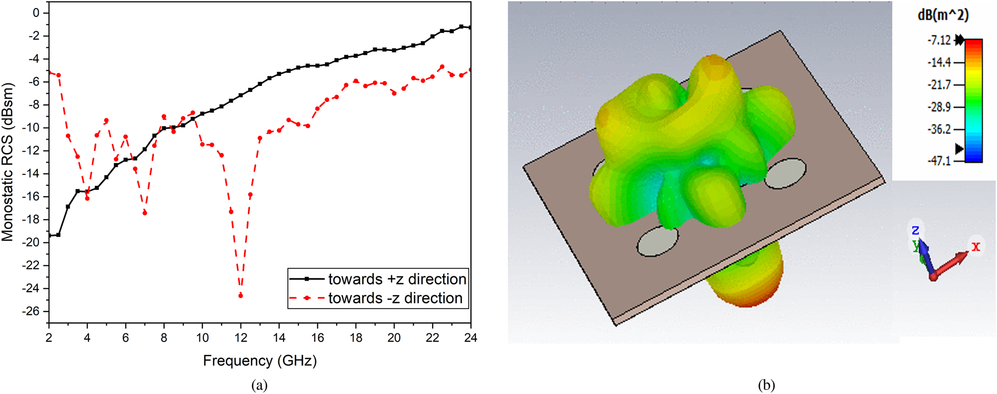
Fig. 16. (a) Monostatic RCS of the proposed antenna. (b) 3D bistatic RCS of the proposed antenna at 12 GHz.

Fig. 17. Surface current distribution of antenna at 12 GHz. (a) Top and (b) bottom.

Fig. 18. E-field distribution of the proposed antenna at 12 GHz.
The comparison of RCS results of the designed antenna and the same-sized metallic plate is shown in Fig. 19. It is observed that the designed antenna exhibits maximum reduction in the RCS of 19 dB when compared with metallic plate at 12 GHz. It is also seen that the proposed antenna shows an average of more than 6.1 dB scattering suppression in the range of 10–24 GHz. However, the proposed antenna RCS is almost the same as of the metallic plate within the working band. Figure 20 shows the monostatic RCS of the proposed antenna and the metallic plate at 12 GHz with respect to incident angles −90° to +90° for horizontal and vertically polarized impinging wave. It is seen that the designed antenna attains remarkable RCS reduction for −30° to +30°. Finally, the designed structure is compared with some other works and listed in a tabular form in Table 1. The designed MTS antenna exhibits a notable enhancement in axial ratio as well as in IBW. The gain of the proposed antenna is better than [Reference Wang, Dong and Itoh10, Reference Han and Dou14, Reference Rajanna, Rudramuni and Kandasamy15, Reference Huang and Wen18] while 3 dB ARBW is good as compared to [Reference Wang, Dong and Itoh10, Reference Hussain, Tran and Le13, Reference Rajanna, Rudramuni and Kandasamy15, Reference Huang and Wen18].

Fig. 19. Simulated and measured monostatic RCS of metallic plate and proposed antenna.

Fig. 20. Monostatic RCS of metallic plate and proposed antenna at 12 GHz for (a) h-polarized and (b) v-polarized incident EM wave.
Table 1. Comparison between the proposed antenna and other CP antennas mentioned in the literature

Conclusion
A CP high-gain low-profile single-layer MTS antenna with low RCS is presented in this paper utilizing CMA technique. The feed point of the antenna is also predicted with the help of CMA and the microstrip feed is placed at the correct location to stimulate the required modes (i.e. modes 2 and 3). The proposed CP MTS-based antenna attains UWB working band of 96.93% and 3 dB axial ratio band of 41.8%. The dimension of the antenna is 0.67λ 0 × 0.67λ 0 × 0.040λ 0, which validates the miniaturization and low-profile identity of the antenna. At 7.97 GHz, the proposed antenna has a bi-directional radiation pattern with a maximum gain of 7.9 dBi. The proposed antenna shows significant RCS reduction in the range of 10–24 GHz. The designed antenna can be a potential candidate for a wide range of applications in c- and x-band.
Author contributions
Conceptualization, validation, writing – review and editing: Priyanka Jain; methodology, software, writing – original: Sourabh Rana; analysis, investigation: Sourabh Rana and Priyanka Jain. All authors have read and agreed to the published version of the manuscript.
Financial support
This research received no specific grant from any funding agency, commercial, or not-for-profit sectors.
Conflict of interest
The authors declare that they have no known competing financial interests or personal relationships that could have appeared to influence the work reported in this paper.
 Mr. Sourabh Rana is Assistant Professor in the Department of Electronics & Communications Engineering at Bharati Vidyapeeth College of Engineering, New Delhi. He is currently pursuing Ph.D. from Delhi Technological University, Delhi, India. He has a teaching experience of more than 6 years. His current research interests include metamaterials, metasurfaces, characteristics mode analysis, and RCS reduction of antennas.
 Dr. Priyanka Jain is a Professor in the Department of Electronics & Communications Engineering at Delhi Technological University, Delhi, India, where she has been a faculty member since 2011 with overall teaching and research experience of 22 years. Her research interests lie in the area of Signal Processing and Microwave Engineering. Dr. Priyanka Jain is author/co-author of more than 35 National and International journal papers and more than 50 publications in National and International conference proceedings. Four students have already been awarded Ph.D. degree under her guidance, and another six are pursuing Ph.D. under her. She has received Commendable Researcher Excellence Award since last three years.


