I. INTRODUCTION
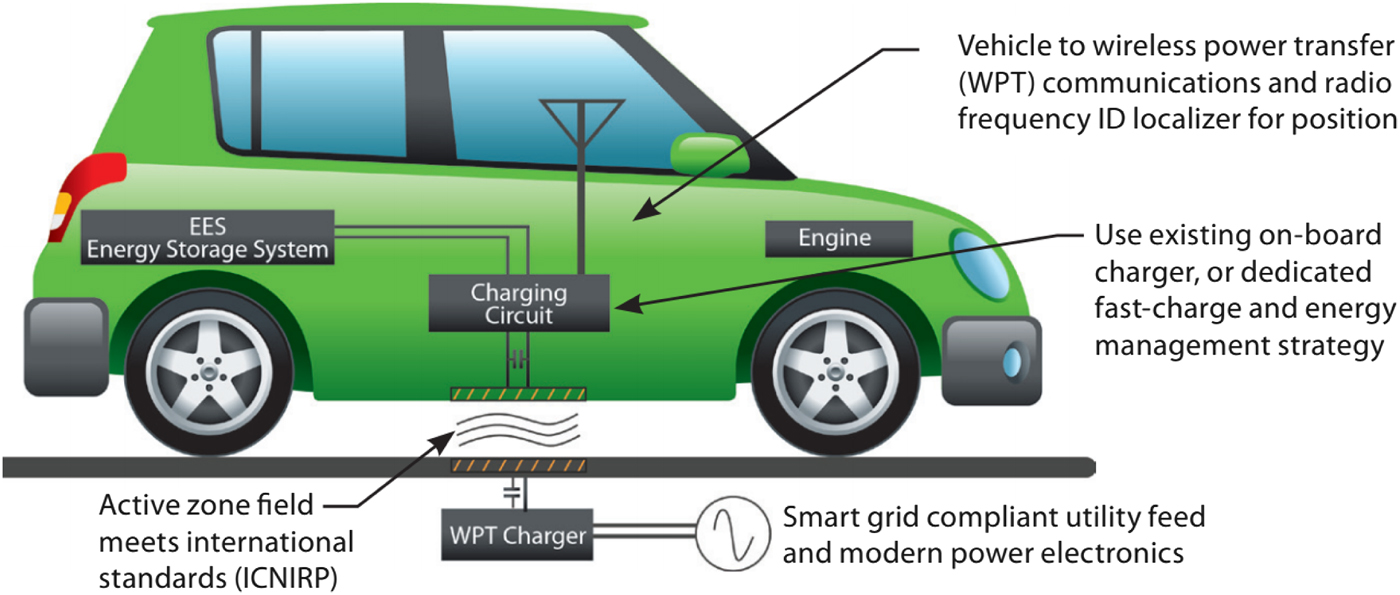
Electric vehicle wireless charging (EVWC) technology operates on the principles of magnetic inductance and magnetic resonance. Similar to the way a transformer operates, a magnetic field is induced in the surrounding area by running currents through a coil of wire. Exposing another coil nearby to that magnetic field will induce an electric current in the nearby coil; thus, wireless power transfer (WPT) is achieved. However, unless the coils are very close together and aligned correctly, this power transfer method, known as inductive power transfer, typically has a suboptimal efficiency [Reference Mur-Miranda1, Reference Cheon, Kim, Kang, Lee, Lee and Zyung2].
To increase the WPT efficiency at longer distances between the source and the receiver with poor alignment, magnetic resonance is introduced [Reference Cheon, Kim, Kang, Lee, Lee and Zyung2–Reference Kurs, Karalis, Moffatt, Joannopoulos, Fisher and Soljačić6]. This involves “tuning” the source and receiver circuits so that they both magnetically resonate at the same frequency, which greatly improves WPT efficiency. Some research has demonstrated that optimizing shape, arrangement, and number of the turns in the transmission and receiver coils can increase the WPT efficiency [Reference Imura, Okabe, Uchida and Hori7, Reference Lee and Lorenz8]. In addition, a number of specialized circuits are required to convert the AC signal to DC to charge the battery, as well as to regulate the voltage and current levels that can greatly fluctuate depending on the alignment of the coils [Reference Esteban, Sid-Ahmed and Kar9].
In the past decade, electric vehicles (EVs) have gained popularity due to concerns about polluting the environment with greenhouse gases and a desire to move toward “greener” energy [Reference Jin and Rim10, Reference Shapiro11]. However, plug-in EVs have their problems: they require the user to change his or her behavior by remembering to plug in the EV, and their charging infrastructure (public charging stations) is vulnerable to weather (rain, snow, and ice) and vandalism (stealing the cord, blocking the outlet). The cord can pose a trip hazard, and due to the large amount of power being transferred, it also carries the risk of electrocution [Reference Wu, Gilchrist, Sealy, Israelsen and Muhs12].
Wireless charging (WC) technology for EVs may improve upon EV convenience and related infrastructure as well as charging safety. EVs that are charged wirelessly are easy to use – the user simply parks the EV and allows it to charge. WC infrastructure can be buried or built into the ground and completely sealed with no outlets, making it inherently safe from weather, vandalism, and electrocution hazards. Well-distributed WC facilities available for EV charging could allow more frequent charging and shorten the charging time required. Infrastructure allowing EV users to “park and charge” their vehicles virtually everywhere may lead to battery size reductions and lightweight EV designs.
With stationary WC, the user simply parks the vehicle over a charging pad on the floor, and a corresponding charging pad mounted on the underside of the vehicle picks up the signal and charges the vehicle. Similar WC technology has already been applied in public transportation systems at bus stops in what is known as “opportunity charging”. When the bus idles at a bus stop, charging coils embedded in the road charge the bus for as long as it remains at the stop. This system has allowed electric city buses to reduce their battery sizes, thus making the buses more efficient by reducing their weight. Similar technology could also reduce the size of the heavy batteries carried by electric cars and other vehicles.
WC technology could further be used for dynamic WC, i.e. charging while the vehicle is moving. Usually, dynamic WC concepts involve a single charging pad or a string of charging pads that are built into the road or highway, and each charging pad is activated for a split second as the car passes over it [Reference Miller, Scudiere, McKeever and White13–Reference Kesler15]. Charging a vehicle while it travels on the highway would mean that an EV user would not have to make stops to recharge during extended road trips. A designated WC lane for EVs on highways could sustain EVs for hours, eliminating range anxiety.
This paper endeavors to review the developing WC technologies for EVs available in the literature. We first describe the WC systems in development and in use, including technical specifications where available. Automobile manufacturers that have taken an interest in WC technology are reviewed briefly in the next section. Research from universities and research laboratories on EVWC technology is then examined. Finally, the safety of EVWC technology is discussed.
II. WIRELESS EV CHARGING TECHNOLOGY COMPANIES
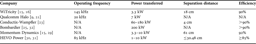
There are a few major players in the EVWC field, including WiTricity, Qualcomm, Conductix-Wampfler, Bombardier, EVWireless, and Momentum Dynamics. WiTricity is a start-up in Watertown, MA that began at the Massachusetts Institute of Technology. Their commercialized EVWC technology involves receiver and transmitter charging pads that operate on WPT via strongly coupled magnetic resonances (WiTricity) [Reference Kesler15]. The receiver pad attaches to the bottom of the car, and the transmitter pad stays on the garage floor or is embedded in a paved parking spot, as shown in Fig. 1(a) [Reference Kesler15, 16]. This system incorporates a source-driving coil, two well-tuned resonance coils, and a receiver-driving coil. The two resonance coils, in spite of their relatively low coupling factor due to their separation, are tuned to resonate at the same frequency [Reference Joannopoulos, Karalis and Soljacic17, Reference Karalis, Kurs, Moffatt, Joannopoulos, Fisher and Soljacic18], so that energy can be transferred over a distance. Coupling factor is referred to the magnetic interference between the Transmission (Tx) and Receiving (Rx) coils. Tuning the two circuits' resonance frequencies and matching their impedances greatly increases efficiency and decreases power losses from the system. WiTricity's system has an efficiency of about 90% and a power transfer rate of up to 3.3 kW [16, Reference Breitrose19, Reference Lutterman20]. Energy transfer can occur through any non-metallic surface, meaning that the floor pad can be installed below a garage floor or embedded in pavement. Its operating frequency is about 145 kHz, and its lateral position tolerances are ±20 cm side-to-side and ±10 cm bumper-to-bumper [16].
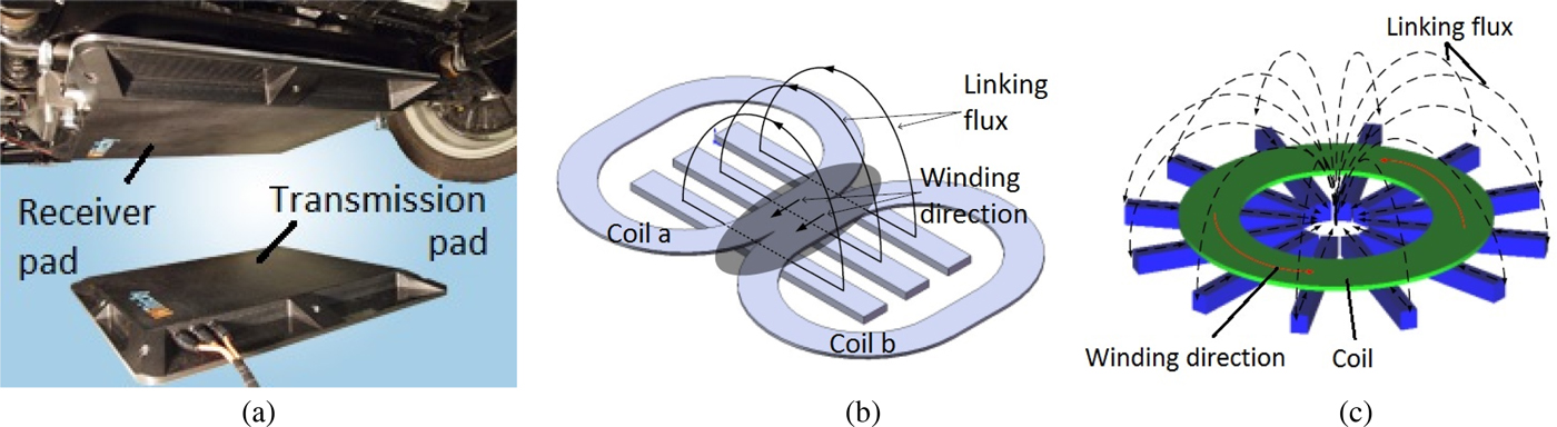
Fig. 1. (a) WiTricity's highly resonant WC pads for electric vehicles [16]. (b) Qualcomm Halo's patented “Double D” coil design as compared to (c) a traditional circular coil design (left) [21].
Qualcomm's Halo group has developed stationary WC pads in collaboration with the University of Auckland [Reference Boys and Covic21]. Their patented “Double D” magnetic polarized pads (Fig. 1(b)), are claimed to have a unique arrangement that delivers twice the power with a higher efficiency compared to circular pads (Fig. 1(c)) [Reference Boys and Covic21]. Qualcomm is still in the process of investigating the best charging frequency to use for their EVWC devices, but uses 20 kHz as their frequency of choice in their HaloIPT system as of 2012 [Reference Esteban, Sid-Ahmed and Kar9]. In 2011, Qualcomm announced that their pads were scheduled to undergo a trial run in East London's Tech City [22]. In the future, Qualcomm hopes to develop a dynamically charging system that would power motors directly as users drive. This would increase the efficiency dramatically, since charging the battery rather than the motor itself introduces power losses of about 15% [Reference Boys and Covic21].
Conductix-Wampfler's inductive WC system has already been operating in the electric buses in Torino, Italy for the past 10 years [23]. Their system consists of a primary (stationary) side, which is installed on the road, and a secondary (vehicle) side, which uses one or more pickups and rectifiers. As shown in Fig. 2, energy is delivered from a track supply through the primary coil to a battery bank. Conductix-Wampfler tunes the resonant frequency of each system individually, and has achieved over 90% efficiency at a separation distance of 4 cm with 60 kW power transfer [23].

Fig. 2. Conductix-Wampfler's WC system schematic [24].
Bombardier's PRIMOVE system addresses both the static and the dynamic charging needs of buses, cars, and even light rail systems [25]. Currently, Bombardier's dynamic charging has only been applied to light rail systems, using single charging pads built into the track; however, it could be adapted for use with road vehicles. The system's roadside components for buses include: primary coils that provide the inductive magnetic field; shielding to prevent electromagnetic interference; a vehicle detection and segment control (VDSC) cable that identifies PRIMOVE vehicles above the system; a supervisory control and data acquisition (SCADA) interface that supplies information for system control and diagnostics; and inverter and power supply cables. The onboard vehicle components include a power receiver system of pickup cables and a compensation condenser, inverters, a battery, and a VDSC antenna. Their system is currently being used in public transportation by buses in Braunschweig, Germany [26].
EVWireless has developed EV wireless chargers that use pulse transmission nanocomposite magnetic coupling (PTNMC) technology [Reference Tran27]. In spite of lacking publication references, their website claims that the pulse transmission mechanism can effectively control the switching frequency and charging duty cycle on demand, allowing electrical energy to be supplied intermittently at high voltage and high frequency with great efficiency. They also claim that the use of nanocomposite carbon–copper coil designs improves efficiency due to improved signal-to-noise ratio properties of the material. In addition, they claim that their device, a 420-mm diameter pad, will address both stationary and dynamic WC needs.
Momentum Dynamics has developed a product using magnetic induction in much the same way that the other companies' devices do [28]. They have also developed software that would enable energy suppliers to collect money from those who use their system to charge their EVs in a manner similar to Automatic Toll Collection Systems. Their system can rapidly charge commercial vehicles using a power system that supplies 240 V through air gaps of up to 24 inches. It is claimed that their system can achieve 92% efficiency rates [Reference Kesler15]. Their founder and CEO, Andy Daga, stated that the product can currently transfer 3.3 kW of power, and that upgrades to 7.2 kW and then to 10 kW were planned. With these upgrades, the system could charge a car such as the Chevy Volt in approximately 1 h [Reference Cobb29]. Momentum Dynamics' systems are currently being implemented in select FedEx trucks from Smith EVs.
HEVO Power is another company that is implementing static and dynamic WC zones, or “green parking zones,” for city EV owners, aiming to reduce fuel costs and emissions [Reference Jeremy McCool, Sharma and Okolski30]. Their system uses a unique smartphone app that finds open parking zones and helps drivers align the power station on the ground with the receiver on their car, using built-in alignment sensors on both the power station and receiver. The app also allows users to access charging information remotely. The charging station operates at 85 kHz and transfers 1–10 kW of power. It charges at an 85% or greater efficiency with air gaps less than or equal to 12 inches. The power receiver on the vehicle weighs 25–50 lbs [Reference Maxwell Fine31]. HEVO Power also claims the ability to bend the magnetic field around any objects caught between the car and the power station, to prevent heating of those objects [Reference Jeremy McCool, Sharma and Okolski30].
Table 1 summarizes commercialized EVWC technologies and their specifications.
Table 1. EVWC companies.
III. AUTOMOBILE COMPANIES ADOPTING EVWC TECHNOLOGY
Several automobile companies are developing WC technology or are working with other companies to develop WC technology. Delphi, Inc. has partnered with WiTricity to make use of WiTricity's unique stationary charging technology [Reference Motavalli33]. Likewise, Toyota, Mitsubishi, and Audi have also shown interest in WiTricity's WC technology [Reference Stewart34].
Plugless Power devices, manufactured by Evatran LLC, are available for the Nissan Leaf and the Chevy Volt [35]. This technology addresses stationary charging needs for home users.
Reportedly, BMW and Nissan are developing WC technology for EVs [36]. BMW is working with Siemens Corporation on an inductive charging system, with trials that were supposed to begin in June of 2011 in Berlin [Reference Ingram37]. Nissan is developing a WC system for its 2015 Infiniti LE four-door luxury electric car with an automatic parking system to ensure the car is parked directly over the charging pad [Reference Voelcker38].
Daimler, Audi, Opel, BMW, and Volkswagen are all participating in a project sponsored by the German government, the goal being to create a house that generates more electricity than it consumes [Reference Quick39]. The house is designed to be energy efficient and is equipped with energy management technology. It uses photovoltaic cells to generate electricity, and any excess energy it generates will be stored in batteries to charge EVs. Each automaker donated one EV to the cause for a period of 3 months to be charged with stationary WC pads in the house's garage. Daimler was the first to donate a car in March 2012; they donated a Mercedes-Benz A-Class E-CELL with an inductive WC system added as a modification.
IV. EVWC RESEARCH STUDIES
At Korea Advanced Institute of Science and Technology (KAIST), Jin Huh et al. worked on a project known as On-Line Electric Vehicles (OLEV), in which they designed four stages of wirelessly charged EVs that draw power from an electrically charged road grid [Reference Jin and Rim10]. In the first phase, they transferred approximately 3 kW output power across an EV air gap of 1 cm at an efficiency of about 80%. Their second phase involves an EV with an ultra-slim U-type mono rail, which yields 52 kW output power and produces an efficiency of 72%. The second stage's air gap jumped from 1 to 17 cm. One of KAIST's third generation OLEVs is a sport utility vehicle (SUV) with an ultra-slim W-type rail that operates with 71% efficiency at the same 17 cm air gap, obtaining 15 kW per EV operating on the mono rail. KAIST also made a third-generation bus with an improved efficiency of 83% and a 20-cm air gap, as well as a train with 74% efficiency and a 12-cm air gap. KAIST is currently working on a fourth-generation bus with underground narrow power rails [Reference Jin and Rim10].
A spin-off company from Utah State University called Wireless Advance Vehicle Electrification (WAVE) has developed an electric transit bus that is charged wirelessly [Reference Foy40]. Charging pads embedded in the concrete roadways at strategic locations charge the electric bus via magnetic induction. It currently operates at 25 kW, but the company plans to upgrade to 50 kW by mid-2013 [Reference Kesler15]. The buses are intended to serve the University of Utah campus, but the company still needs to ensure the WC pads will not interfere with someone's pacemaker should a person fall chest-first onto the charging pad. The system provides an 85% battery weight savings for the electric bus over conventional EV battery packs.
Oak Ridge National Laboratory (ORNL) has developed an EVWC system that could be used statically or dynamically [Reference Scudiere and Miller41]. The ORNL discovered that an operating frequency set at 50–95% of the resonant frequency can result in optimal power transmission efficiency. Their system uses a transformer with an air core, which is loosely coupled to the storage battery. The ORNL system also enhances the system's efficiency by using a coupling coil as well as carbon nanotube or graphene wire coatings [Reference Scudiere and Miller41]. A schematic of ORNL's system is found in Fig. 3.

Fig. 3. Oak Ridge National Laboratory's EVWC system [41].
The University of Auckland partnered with Daifuku and Conductix-Wampfler to develop an inductive EVWC system for a monorail device, and later for electric road vehicles [Reference Madawala and Thrimawithana42]. Their system uses inductive power transfer and has been tested at 1.5 kW with a 4-cm air gap. A diagram of their power pad design is shown in Fig. 4(a). The design may be used someday as a dynamic charging lane with long series of these charging pads to charge vehicles on long trips, as depicted in Fig. 4(b).
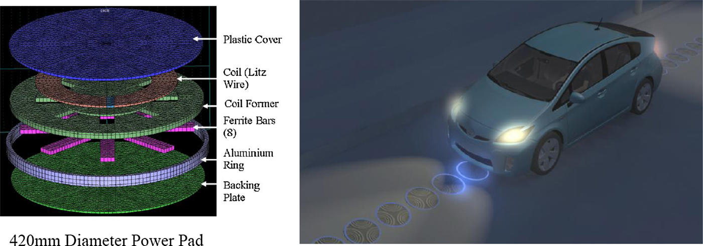
Fig. 4. Diagram and vision of the power pad design from the University of Auckland [14]. (a) Power pad diagram and (b) vision for future dynamic use of power charging pads.
A study on different geometries of coils for WPT using electromagnetic waves was done by Horiuchi and Kawashima at Setsunan University [Reference Horiuchi and Kawashima43]. The shapes of horn, patch, and array antenna coils were respectively tested. While the horn-shaped antennas are the most efficient, this shape is rather impractical for electric vehicles because of its three-dimensional nature. The patch antenna is a more practical shape for electric vehicles because it is planar in nature, but its efficiency was lower than the horn antenna. Reducing the patch antenna frequency from 2.45 to 1.20 GHz greatly reduced the transmission loss; the array antenna at the 2.45 GHz frequency also showed reduced transmission loss compared to the patch antenna at the same frequency.
At Tokohu University, research was done on the Tx–Rx coupling factor and efficiency when the gap between coils was changed, using a basic resistive–inductive (RL) circuit and resistive–inductive–capacitive (RLC) circuit booster on the receiving side [Reference Sato, Morita, Takura, Sato and Matsuki44]. They found that the larger the gap, the lower the efficiency and coupling factor.
Wu et al. at Utah State University reported on their 5 kW inductive charging design for EVs [Reference Wu, Gilchrist, Sealy and Bronson45]. They have achieved 90% and higher efficiency levels with their system under full loads, and this efficiency can even be increased by 7% at light loads.
The University of Tokyo studied the feasibility of an EVWC system based on magnetic resonance [Reference Imura, Okabe and Hori46]. They discovered that while the transmission and receiving coils with large air gaps couple weakly by using magnetic resonance, they could still transfer energy at a high efficiency. The paper also mentions WiTricity, the spin-off from MIT that uses magnetic resonances to transfer power in a strongly coupled frequency range in the order of megahertz [Reference Kurs, Karalis, Moffatt, Joannopoulos, Fisher and Soljačić6]. WiTricity was able to transfer power over 2 m gaps with about 40% efficiency. This efficiency improved as the air gap was closed (Fig. 5). Researchers at the University of Tokyo also described a new technique for EVWC using near-field coils at resonance [Reference Imura, Okabe, Uchida and Hori47]. This technique can transfer power with high efficiency over large air gaps, making it ideal for EVs; however, it is still being optimized.
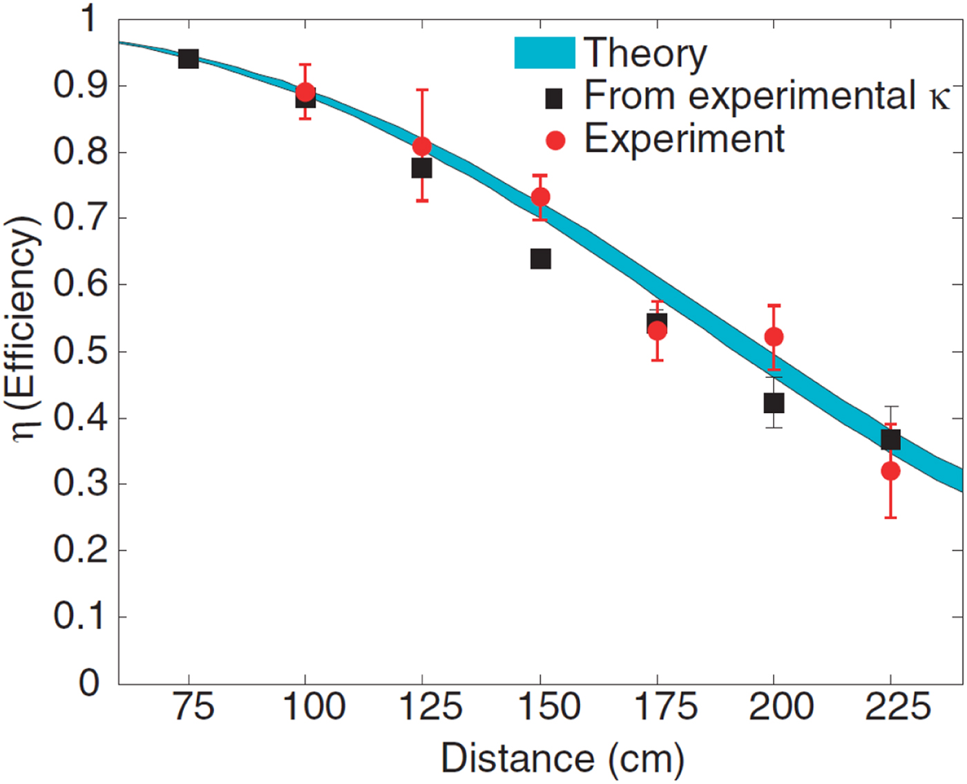
Fig. 5. WiTricity's theoretical predictions and experimental results for power transfer efficiency as a function of the distance between the coupled coils [6].
The researchers at the University of Tokyo also reported that when power is transferred via magnetic resonance coupling, impedance matching tuning circuits can help optimize the efficiency of power transfer and minimize reflection [Reference Beh, Kato, Imura and Hori48]. Figure 6(a) shows a schematic of their RLC circuits. As shown in Fig. 6(b), the transfer and reflection ratios form two peaks at smaller gap distances, and as the distance increases, the two peaks merge into one. At much higher gap distances, the single peak drops down and the maximum transfer efficiency decreases. An impedance matching circuit controlled by a computer was used to tune the resonant frequency of the system to match the power source (about 13.56 MHz). As a result, the power transmission efficiency greatly increased (Fig. 6(c)).
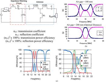
Fig. 6. The University of Tokyo's WC system (a) circuit schematic, (b) frequency versus power transmission (η21) and reflection (η11) ratios for different gap lengths, and (c) experimental effects of the impedance matching circuit on the frequency versus efficiency graph at a gap of 13 cm [48].
Figure 7 shows a typical WC topology [Reference Zhen Ning, Chinga, Ryan and Jenshan49], which contains the AC/DC portion using interleaving topology and the DC/DC portion employing full-bridge resonant topology. Half-bridge resonance is another choice, depending on the input and output voltages. Here two coils, LP, LS, CS, and CP, form the resonance network. Other types of resonant networks could be used as well [Reference Zhen Ning, Chinga, Ryan and Jenshan49].
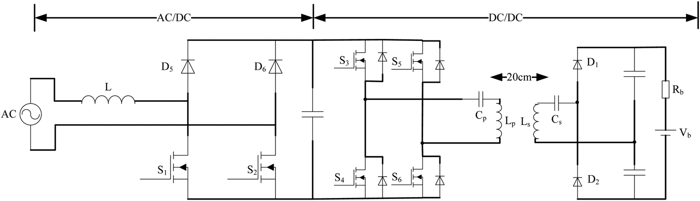
Fig. 7. The proposed WC circuit [49].
The CoolMOS MOSFET was adopted [Reference Zhen Ning, Chinga, Ryan and Jenshan49] due to its low internal resistance and thereby low on-state loss. Its major demerit is the poor performance of its body diode, which usually has high reverse recovery loss in the hard turn-off mode, not only leading to low system efficiency but also creating significant electromagnetic interference (EMI). Therefore in most high-efficiency battery chargers, softly turning on the CoolMOS, i.e., softly turning off its body diode, is preferable. Figure 8 displays the MOSFET voltage VDS (blue) and current ID (red). It indicates that right before the MOSFET turns on, the current flowing through the MOSFET is still negative, i.e., flowing through its body diode. After the MOSFET turns on, the current commutates from its body diode to the MOSFET channel, i.e., softly turning on. When the current polarity is reversed, the MOSFET body diode is naturally turned off without any reverse recovery loss. This commutation process realizes zero voltage switching (ZVS).
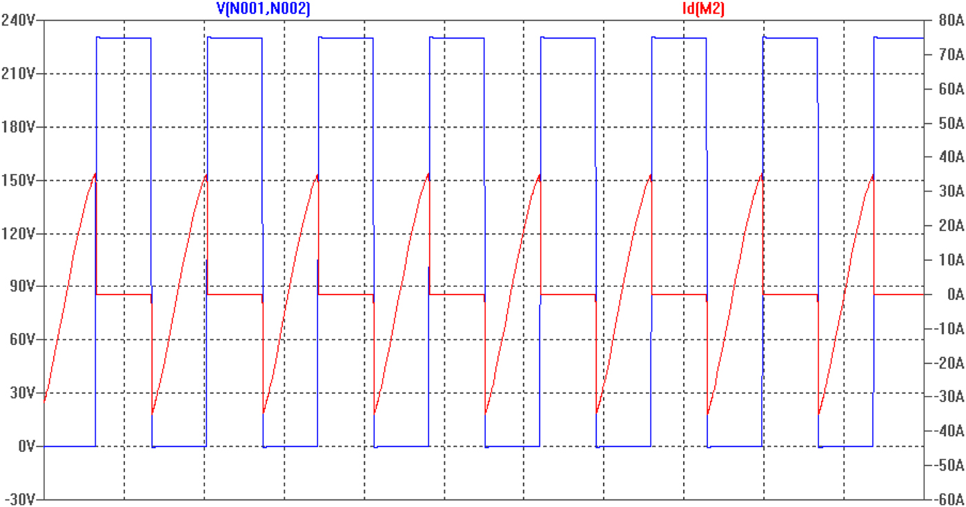
Fig. 8. Soft switching of the MOSFETs in the DC/DC portion (VDS – blue, ID – red) [50].
The AC/DC portion also needs high efficiency (>97%) operation and a high power factor (>0.99). The topology adopted in Fig. 8 is an interleaving circuit, which needs a much smaller inductance compared to other AC/DC circuits. It can also realize ZVS of S1 and S2. Here, the gate signals of S1 and S3 have a 180° phase difference, with each leg undertaking half of the overall power. The interleaved number will vary based on the input type, i.e., single phase or three phase [Reference Pellegrino, Armando and Guglielmi50]. The interleaved topology is essentially a unidirectional converter. If bidirectional power flow is required, the full-bridge topology can be utilized [Reference Wei, Hua, Szatmari-Voicu, Taylor, Patterson and Kane51].
Saitama University has partnered with Technova, Inc. and Aisin AW Co. Ltd., in Japan, to produce a device that has a double-sided winding wrapped around the centers of novel H-shaped cores [Reference Chigira, Nagatsuka, Kaneko, Abe, Yasuda and Suzuki52]. Compared to a rectangular core, the H-shaped ferrite core decreases the weight of the transformer, reduces copper losses due to shorter windings, and enhances tolerance to lateral misalignment due to the increased length of the magnetic poles in the lateral direction. The design also includes an aluminum sheet attached to the back of the pick-up coil to prevent leakage flux. At an air gap of 7 cm and power transfer rate of 1.5–3.0 kW, the device has an average efficiency of about 94%.
One unique system designed and in use at the University of British Columbia (UBC) does not use resonant inductive wireless power transfer. Instead, it uses a set of magnetic gears, an electric motor, and an electric generator to transfer power [Reference Li53]. The electric motor is mounted on the ground and rotates a magnetic gear, that is coupled to a magnetic gear onboard a car (Fig. 9). The coupled magnetic gear turns the generator onboard the car, generating electricity, which is stored in the car battery. The system operates at a significantly lower frequency than typical resonant and inductive systems, about 150 Hz, and achieves an efficiency of about 81%. It transfers 1.6 kW of power over a distance of 15 cm. The system is currently used to charge EVs when they are parked on the UBC campus.

Fig. 9. A photo of the University of British Columbia's magnetic gear WC device [53].
Table 2 contains a list of the above reviewed research work and the various specifications for each system developed.
Table 2. EVWC research.

V. SAFETY AND REGULATIONS
All the above breakthroughs in EVWC technology are of limited usefulness to the EV market if they cannot be made safe for human contact and interaction. Researchers developing EVWC systems should also check the safety of their systems and make sure that their WC devices conform to safety standards. The “Standard for Safety Levels with Respect to Human Exposure to Radio Frequency Electromagnetic Fields, 3 kHz to 300 GHz” is made by the Institute of Electrical and Electronic Engineers (IEEE) [54]. Guidelines for limiting exposure to time-varying electric, magnetic, and electromagnetic fields (up to 300 GHz) are made by the International Commission on Non-Ionizing Radiation Protection (ICNIRP) [55]. In the USA, safety standards are governed by the Federal Communications Commission (FCC) [Reference Commission56]. These standards are set to protect humans from the adverse health effects caused by electromagnetic radiation from man-made devices.
Both the IEEE and the ICNIRP have determined that there is no strong evidence that exposure to electromagnetic fields causes cancer. However, other adverse health effects are possible, including tissue heating as well as nerve and muscle stimulation. Retinal phosphene visualization is another possible effect; that is, electromagnetic waves can induce the sensation of light in the retina without light actually being present. These effects should all be considered when determining standards. The current standard all three organizations agree upon for tissue heating is set at a specific absorption rate (SAR) of 0.08 W/kg for the general public for a long-term environmental exposure, and set at an SAR of 4 W/kg for a short-term exposure (1st level controlled), which is equivalent to a maximum of 1°C rise in body temperature [Reference Pellegrino, Armando and Guglielmi50, 54, 55].
Nerve and muscle stimulation, including retinal phosphenes, do not have any known direct or lasting adverse health effects; however, all three standard-setting organizations have decided that these effects should be avoided. The internal electric field limit set by the IEEE depends on the part of the body exposed, and ranges from 2.1 × 10⁻⁴ to 6.3 × 10⁻⁴ × f V/m, where f is the electromagnetic field frequency in Hz [54]. The ICNIRP recommends a slightly lower field limit of 1.35 × 10⁻⁴ × f V/m [55]. Computational studies and experimental measurements are possible methods to study the electric field and SAR of a human body standing near a charging automobile. Indeed, some computational studies have been done by Kesler et al. to investigate the electric field and SAR levels generated by the WiTricity system [Reference Kesler15]. Magnetic field measurements have been taken to quantify the field strengths at different positions of a human body standing near an EVWC device in operation [Reference Hunter, Wu, Sealy and Bronson57], including at the positions of the knee, groin, chest, and head. A similar study has been conducted to measure the magnetic field strengths at the driver side front tire, floor board, driver seat, and head rest of an EV being wirelessly charged [Reference Onar, John, Campbell, Coomer, White and Seiber58].
VI. CONCLUSION
EVWC technology is growing quickly and moving forward. Charging systems are starting to become commercially available as the EV market slowly grows, and the improved infrastructure is bound to boost the popularity of EVs. Further developments are increasing EVWC efficiency, and many players in the EVWC field are competing for space in the newly formed market niche. The many uses of EVWC include stationary applications such as home garages, public parking spaces, and opportunity charging stations, while dynamic applications include highway-charging lanes that would allow EVs to continuously drive on the highway for hours without stopping to charge. Behind these applications, magnetic resonance and induction technologies are being developed, so that the efficiency of WC can rival that of traditional plug-in charging.
This paper has reviewed solutions available in the literature from a myriad of companies working on the EVWC problem, including WiTricity, Qualcomm Halo, Conductix-Wampfler, Bombardier, EV Wireless, Momentum Dynamics, and HEVO Power. We have also reviewed the car manufacturers interested in adopting EVWC technology, including Delphi, Toyota, Mitsubishi, Audi, Nissan, Chevy, BMW, Daimler, Opel, and VW. Finally, we have reviewed the technical research that has been done by researchers at several universities and laboratories on the subject of EVWC technology, such as KAIST, Utah State University, ORNL, the University of Tokyo, the University of Auckland, Setsunan University, Tokohu University, Saitama University and the University of British Columbia. Safety and regulations have also been discussed. EVWC technology is still in its infancy, but it promises to change the world of EVs for the better.
FINANCIAL SUPPORT
This research received no specific grant from any funding agency, commercial, or not-for-profit sectors.
CONFLICT OF INTEREST
None.
 Zion Tsz Ho Tse received his Ph. D in Mechatronics in Medicine from Imperial College London. Currently he is an assistant professor in the College of Engineering and the Principal Investigator of the Medical Robotics Lab at the University of Georgia, Athens, GA, USA. Before joining UGA, he was a research fellow at Harvard Medical School and Brigham and Women's Hospital. Dr. Tse has been involved in designing and prototyping a broad range of novel analog-digital electronic devices, most of which have been applied in numerous clinical and industrial environments.
 Yabiao Gao is pursuing his Ph.D in wireless power transfer at the College of Engineering, the University of Georgia, Athens, USA. Before joining UGA, he received both Bachelor's and Master's degrees from the Department of Precision Instrument Engineering from Tianjin University, Tianjin, China, in 2009 and 2011, respectively.
 Kathleen Blair Farley is a research engineer at Southern Company Services, Inc, specializing in Electric Transportation. In this role, she evaluates both on-road and off-road forms of electric transportation and their interaction with the electrical grid. She holds a Bachelor's degree in Mechanical Engineering from the University of Alabama at Birmingham and is currently pursuing her Master s degree there with a focus on mechanical driveline efficiency.
 Hua Bai received his Bachelor's and PhD degrees from the Department of Electrical Engineering of Tsinghua University., Beijing, China in 2002 and 2007, respectively. Bai was a post-doc fellow and research scientist in University of Michigan-Dearborn, USA, in 2007 and 2009, respectively. Now he is an assistant professor in the Department of Electrical and Computer Engineering, Kettering University, MI, USA. His research interests are the dynamic processes and transient pulsed power phenomena of power electronic devices, including variable frequency motor drive systems, high voltage and high power DC/DC converters, renewable energy and hybrid electric vehicles.
 Taylor M. Fisher received her Bachelor's Degree in Biological Engineering from the College of Engineering, the University of Georgia, Athens, GA, USA, with a focus in Biomedical Engineering. She currently works as a scientific editor for the Medical Robotics Lab at the University of Georgia.