


Introduction
Naturally occurring and man-made symmetrical structures surround us on a daily basis (Belaroussi et al., Reference Belaroussi, Foucher, Tarel, Soheilian, Charbonnier and Paparoditis2010). The widespread occurrence of symmetry has inspired both artists (like M.C. Escher) and scientists (Weyl, Reference Weyl1952; Gardner, Reference Gardner1964). In biology, we also encounter symmetry at every scale, starting from the whole organism level, where most animals exhibit symmetry along the vertical axis, down to organs like our brains. Even further down the scale, we find symmetry in dividing cells and mitochondria. Finally, on the molecular level, we find symmetry in macromolecular machineries like nuclear pores and receptor arrays in bacteria. At the microscopic level, symmetry is often key to the proper function of core biological processes. For example, bacteria rely on highly ordered symmetrical arrangement of thousands of receptors to accurately sense their chemical environment. Furthermore, changes in symmetry over time give crucial insight into biological processes, such as cell division or vesicle trafficking events. In order to study these structures, we need to first distinguish them from nonsymmetrical areas (Polak & Trivers, Reference Polak and Trivers1994). The need to determine symmetrical areas in images is not new, and multiple approaches to do this have been developed p reviously. Most of these methods depend on the identification of edges and then move forward to analyze the symmetry of these edges (Van Gool et al., Reference Van Gool, Moons, Ungureanu and Pauwels1995; Zabrodsky et al., Reference Zabrodsky, Peleg and Avnir1995). These methods all require that the intensity of the structures stand out from the background sufficiently to be detected by edge filters before detecting symmetry. Some methods use an even more basic concept of point recognition (Evans et al., Reference Evans, Wenderoth and Cheng2000; Dalitz et al., Reference Dalitz, Pohle-Fröhlich and Bolten2013) or are only capable of detecting circles (Davis et al., Reference Davis, McNamara, Cottrell and Campos2000; Loy & Zelinsky, Reference Loy and Zelinsky2003; Ponížil et al., Reference Ponížil, Pavlínek, Kitano and Dřímal2007; Giachetti et al., Reference Giachetti, Ballerini, Trucco and Wilson2013). Overall, most approaches for detecting symmetry are aimed at enhancing computer vision (Reisfeld et al., Reference Reisfeld, Wolfson and Yeshurun1995), for example, to recognize cars or road signs, and can without adaptation not be applied to image analysis in a broader sense. While most methods require edge detections, some are capable of analyzing gray level images but lack a simple implementation method (Kovesi, Reference Kovesi1997; Kiryati & Gofman, Reference Kiryati and Gofman1998; Al-amri et al., Reference Al-amri, Kalyankar and Khamitkar2010; Ni et al., Reference Ni, Singh and Bahlmann2012; Cuevas & Sossa Reference Cuevas and Sossa2013) or require extensive user interactions (Ning et al., Reference Ning, Zhang, Zhang and Wu2010). In this paper, we have developed a reflection concept, based on adaptations to the sobel and prewitt filters (Prewitt, Reference Prewitt1970; Duda & Hart, Reference Duda and Hart1973) similar to that applied by Zabrosky et al. and Hauagge and Snavely (Zabrodsky et al., Reference Zabrodsky, Peleg and Avnir1995; Hauagge & Snavely, Reference Hauagge and Snavely2012) and applied it locally to each pixel within an image. For ease of implementation, our tool can be directly implemented into ImageJ/FIJI (Schneider et al., Reference Schneider, Rasband and Eliceiri2012), which will allow its use for a broad community of microscopists. Our method allows the identification of symmetry centers within both gray level and color images, and in addition, performs an interactive segmentation based on these features.
Segmentation of images is an essential process in image analysis, which allows the separation of the different image components and the subsequent extraction of the objects of interest. Typically, segmentation is done based on intensity values, either before or after applying filters to the images. Recently, many novel approaches have been published (Al-amri et al., Reference Al-amri, Kalyankar and Khamitkar2010; Benes & Zitova, Reference Benes and Zitova2015; Wu et al., Reference Wu, Zhao, Luo and Shi2015; Han et al., Reference Han, Yang, Zhou and Gui2017), including several machine learning-based methods (Sirinukunwattana et al., Reference Sirinukunwattana, Raza, Tsang, Snead, Cree and Rajpoot2016; Yin et al., Reference Yin, Qian and Gong2017). However, determining the optimal filtering method to separate your structures of interest from the background greatly depends on the individual sample and typically takes a significant amount of time. Our tool combines filtering and segmentation in one plugin for ImageJ/FIJI; it first filters the image and subsequently segments that image in one interactive tool. This allows you to change filter sizes, filter methods, and the segmentation thresholds directly on the original image. Therefore, this approach preserves the original image information during the segmentation and simplifies the use of advanced filter methods.
In summary, here we present a novel, easy to use tool for ImageJ/FIJI that combines advanced filtering methods with segmentation, with the emphasis on symmetry detection in images.
Materials and Methods
Tomographic Data of Chemotaxis Arrays
Cryogenic specimens of lysed Escherichia coli cells were imaged with a Titan Krios transmission electron microscope equipped with a Gatan Quantum energy filter and a Gatan K2 summit direct electron detector. Image acquisition was performed at 300 kV with a zero-loss energy slit of 20 eV. Defocus estimation and the contrast transfer function (CTF) correction were performed using CTFplotter (Xiong et al., Reference Xiong, Morphew, Schwartz, Hoenger and Mastronarde2009). Tomograms were reconstructed using the weighted back projection implemented in the IMOD software package (Kremer et al., Reference Kremer, Mastronarde and McIntosh1996; Mastronarde & Held, Reference Mastronarde and Held2017). With their native hexagonal packing order, chemoreceptor arrays can be readily identified in the tomograms displayed in IMOD. The tomoslices displaying receptor arrays are then exported as individual 2D images in tiff format for analysis.
In vivo Confocal Imaging of Subcellular Vesicles
Zebrafish used in this study were handled in compliance with local animal welfare regulations, as overseen by the Animal Welfare Body of Leiden University (License number: 10,612) and maintained according to standard protocols (zfin.org). All experiments were performed on 3 days postfertilization larvae, which have not yet reached the free-feeding stage. Embryos/larvae were kept in egg water (60 μg/mL Instant Ocean sea salts) at 28.5°C and treated with 0.02% ethyl 3-aminobenzoate methanesulfonate (Tricaine, Sigma-Aldrich Chemie, Zwijndrecht, The Netherlands) for anesthesia before imaging. TgBAC (ΔNp63:Gal4FF)la213; Tg (4xUAS:EGFP-2xFYVE)la214 larvae (Rasmussen et al., Reference Rasmussen, Sack, Martin and Sagasti2015) were mounted with 1.5% low melting point agarose (SERVA) in egg water and epithelial cells were imaged in the thin and optically transparent tail fin area using a Leica TCS SP8 confocal microscope with a 63× oil immersion objective (NA = 1.4). For time-lapse imaging, confocal micrographs were acquired at a time interval of ~1.3 s/image.
Symmetry Test Sets
We used two symmetry test sets to test our plugin, the first one we created ourselves from the standard shapes that are available in PowerPoint. The created slide was then saved as a tiff file and used for further analysis. Other images were taken from a Flickr database on symmetry (Liu et al., Reference Liu, Slota, Zheng, Wu, Park, Lee, Rauschert and Liu2013b) that was constructed for a competition in symmetry detection.
Results and Discussion
Finding Local Symmetry
Here we developed a mathematical formula in order to determine local symmetry within an image. This formula attributes a local symmetry value to a pixel depending on the surrounding pixel values. To illustrate how this calculation works imagine a table of three rows (A–C) and three columns (1–3). If we want to determine the symmetry value using a vertical symmetry axis, column 2 is used as mirror and not taken into account in the symmetry value calculation. For the other cells, the absolute difference between the mirrored cells added up over the vertical axis (column 2) is divided by the sum of all cells taken into account (equation (1) and Fig. 1), and this value is subtracted from 1. This will provide us with a range from 0 to 1 for local symmetry, with the maximum score attributed to a symmetry center similar to previous methods (Zabrodsky et al., Reference Zabrodsky, Peleg and Avnir1995; Hauagge & Snavely, Reference Hauagge and Snavely2012; Dalitzet al., Reference Dalitz, Pohle-Fröhlich and Bolten2013).
 $$\; \eqalign{& {\rm Local\;}\;{\rm Vertical\;}\;{\rm Symmetry} = \cr& 1-\displaystyle{{\vert {\rm {A1-A3}} \vert + \vert {\rm {B1-B3}} \vert + \vert {\rm {C1-C3}} \vert } \over {\rm {A1 + A3 + B1 + B3 + C1 + C3}}}.$$
Fig. 1. Four-axis local symmetry calculations as used by the plugin. All calculations will yield a symmetry score between 0 and 1, where 1 indicates the highest symmetry. Taking the mean of these scores will provide the local symmetry score.
Subsequently, we can calculate the symmetry values using the horizontal axis, as well as the two diagonal axes (Fig. 1), and the mean of these four scores representing the total local symmetry score. The plugin attributes these values to a new image consisting of only these symmetry values, this image can optionally be displayed. This new image is then used to set threshold values, which are displayed as a percentage of the total range of values in the thresholded image. After application of the selected threshold, the original image will be transformed to a binary image, which can be used as a mask to measure data on the original image.
Local Symmetry Values in Noise-Free Images
To test how efficient this local symmetry filter is at detecting symmetrical features, we created a test set of symmetrical structures on a noise-free background (Fig. 2a). The top two rows of this figure contain open shapes that are mostly symmetrical, whereas the third row also contains some shapes with less symmetry; in rows 4–6, these shapes are repeated with solid filling. We can calculate the symmetry for each of these shapes along the four primary reflection axes of a square (top-bottom, left-right, and the two diagonals). Since all shapes have a width of 20 pixels, we set the radius of the symmetry filter at 10 pixels. The results of these calculations are shown in Figures 2c–2f. To calculate the total symmetrical values for the whole image, the average of the four images is taken (Fig. 2b). If we look at the results of the calculated symmetry data, we can use the local maximum symmetry value as an indicator for local symmetry points. For the open shapes, where the symmetry function relies on a line with a width of only one pixel within an even background image, we have relatively low values compared to the structures that have been filled. To determine a threshold level above which shapes are considered symmetrical, the maximal symmetry value of the four least symmetrical shapes (Lightning, and Amorphous 1–3) was taken as a cutoff point. Based on these measurements, we find that a threshold of 0.42 will allow us to detect open symmetrical structures (Table 1). However, this also results in the identification of several false positives and to visualize the plugin's performance, receiver operating characteristic curves [ROC curves (Fawcett, Reference Fawcett2006)] are shown in Figure 3a. Notably, the square shape (A2) and the octagon (E1) are difficult to detect. This stems from the fact that for a square with a width of 20 pixels, the corner-to-corner distance along the diagonal axis is 28 pixels, which falls outside the symmetry detection range. Thus, increasing the kernel size would help identifying these kinds of structures, other shapes that do not get identified in this manner only have one symmetry axis. The open shapes that are identified as false positives are explainable: the parallelogram, the cloud, and explosions contain their symmetrical features on the average outline, and only vary in some extremities. Compared to the open shapes, the filled version of the same shape generally yields a higher maximum symmetry value. In these cases, the internal pixel values also add to the symmetry score. Therefore, a more stringent cut-off value of 0.71, again identified as the maximum symmetry value of the nonsymmetrical structures (Table 1), seems more appropriate. The corresponding ROC curve is given in Figure 3b. The two false negatives have only one reflection symmetry axis. The windmill shape has no reflection symmetry but rotational symmetry and only gets detected with the open shapes based on the combination of the four symmetry axes. The combined symmetry values of each of the four calculated symmetry axes also help in detecting rotated symmetrical shapes. To test this, we have rotated a square over 5° incrementing angles from −45° to 45° and determined the local maximal symmetry value. For these rotated squares, the symmetry scores varied between 0.97 and 1 with the lowest value at 22.5° rotation. A similar simulation with an 8-point star shape resulted in more dramatic differences with values between 0.72 and 0.97, again with the minima at 22.5° rotation (Fig. 4). Nonetheless, these values remain above the previously identified threshold of 0.71 and show that our symmetry filter successfully detects symmetrical structures, even when they have been rotated.

Fig. 2. (a) The first symmetry test set containing 60 PowerPoint shapes created to test the detection of local symmetry. In the top 3 rows, 30 open shapes are shown followed by an equal number of filled shapes (rows 4–6). For future reference, the shapes will be identified by column A–J and row 1–6, (b) the average symmetry scores shown as gray values between 0 (white) and 1 (black). The various symmetry axes are (c) left to right, (d) top to bottom, (e) left bottom to top right, (e) left top to bottom right.

Fig. 3. Receiver operating characteristic curves of the plugin. Operated under various noise conditions ranging from no noise (a,b), 25% noise (c,d), 50% noise (e,f), 75% noise (g,h) to 100% noise (i,j), and ending with salt and pepper noise (k,l). The ROC curves on the left are for the open shapes, whereas the right curves are for the closed shapes.

Fig. 4. Maximum local symmetry plotted over the rotation angles from −45° to 45°. As is visible from the graph variation in maximum symmetry is higher when more extremities arise from the main symmetrical body of the objects.
Table 1. Maximum Local Symmetry Scores of the Shapes from Figure 2a, Both for the Open and Filled Version of Each Shape.

In bold, the false positives are shown, underlined the false negatives based on the 0.42 arbitrary threshold for open shapes and 0.71 for filled shapes, respectively.
Local Symmetry in Noisy Images
To test whether the algorithm can also detect shapes in a less ideal pixel environment, we added noise to the image and tried to distinguish the symmetrical shapes from the nonsymmetrical ones. When we applied random noise with values between 25 and 100% of the standard deviation, most of the shapes are still recognizable (Tables 2 and 3), and the corresponding ROC curves show that increasing the noise makes detecting open shapes more difficult, while the detection of the closed shapes remains equally efficient (Figs. 3c–3l).
Table 2. Filled Symmetry Detection Based on a Threshold Value Determined by the Least Symmetrical Shapes, Quantifying the Symmetrical (Y) versus the Nonsymmetrical Structures (N).

Dark gray indicates misidentifications.
Table 3. Open Symmetry Detection Based on a Threshold Value Determined by the Least Symmetrical Shapes, Quantifying the Symmetrical (Y) versus the Nonsymmetrical Structures (N).

Dark gray indicates misidentifications.
Comparison to Machine Learning
To compare our method to machine learning methods, we have used the Ilastik tool (Sommer et al., Reference Sommer, Straehle, Koethe and Hamprecht2011) to segment our images. For training the machine learning, we created two training sets, the non-symmetrical one used above to determine the symmetry threshold, and in addition, four shapes were selected to represent the symmetry class. These shapes were selected by taking two shapes just above the symmetry threshold determined by our plugin (the 5 point star, and the pentagon), as well as the two highest scoring shapes (the decagon, and the circle with cross). Based on these classifications, the other structures were scored as true positive, false positive, true negative, or false negative (Tables 4 and 5). If we look at the open shapes, the machine learning approach is more successful in identifying symmetrical structures than our algorithm, with 1.7 false positives and 5.8 false negatives on average. Our method, using the same images, yielded on average 3 false positives and 7.8 false negatives. However, if we examine the closed shapes the situation is different, with averages of 2 false positives, and 8 false negatives on average, our method works better on the closed shapes, with averages of 3.8 false positives but only 3.7 false negatives.
Table 4. Closed Symmetry Detection Based on Machine Learning, Quantifying the Symmetrical (Y) versus the Nonsymmetrical Structures (N).

Dark gray indicates misidentifications.
Table 5. Open Symmetry Detection Based on Machine Learning, Quantifying the Symmetrical (Y) versus the Nonsymmetrical Structures (N).

Dark gray indicates misidentifications.
Next, we wanted to see how this plugin performs on real images from two different biological systems: the bacterial chemoreceptor arrays and intracellular vesicles in zebrafish larvae.
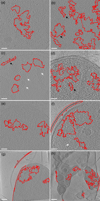
The first example is the bacterial chemoreceptor arrays: they provide motile bacteria the means to sense their chemical environment and control their motility apparatus to seek out beneficial environments. These are composed of thousands of chemoreceptors that are arranged in a highly ordered, hexagonal array. This receptor packing allows for cooperative behavior of the receptors, leading to a high sensitivity, a wide response range, and the integration of a wide range of input signals (Hazelbauer et al., Reference Hazelbauer, Falke and Parkinson2008). Symmetry detection in electron microscopy images has long been a subject of study (Crowther & Amos, Reference Crowther and Amos1971). A lot of progress has been made over the years, both in image analysis methods like IMAGIC (van Heel et al., Reference van Heel, Harauz, Orlova, Schmidt and Schatz1996), as well as technical approaches examining local power spectra (Kim & Zuo. Reference Kim and Zuo2013; Liu et al., Reference Liu, Neish, Stokol, Buckley, Smillie, de Jonge, Ott, Kramer and Bourgeois2013a). However, none of these methods are easily implemented and require expert knowledge (van Heel et al., Reference van Heel, Harauz, Orlova, Schmidt and Schatz1996; Kim & Zuo, Reference Kim and Zuo2013; Liu et al., Reference Liu, Neish, Stokol, Buckley, Smillie, de Jonge, Ott, Kramer and Bourgeois2013a). To simplify the detection of the receptor arrays automatically without machine learning approaches, we have first applied a Gaussian blur to reduce the noise slightly (sigma 1.0). Subsequently, we used the special threshold method (kernel size 13, selection between 20 and 50%, based on trial and error), and lastly filled the holes in the detection regions and analyzed large (>1,000 pixels) image regions. As shown in Figure 5, we were able to detect receptor arrays in all images with the settings described above, except the last panel (Fig. 5h). By adjusting the kernel size to 7 in accordance with the different pixel size in Figure 5h, we can still detect the arrays.

Fig. 5. Detection of chemoreceptor arrays in various tomographic slices in which the areas with detected symmetry are enclosed in the red line. In all panels, the arrays can be distinguished as patches of lattices with repeated hexagonal pattern. Symmetry detection results fit array locations in all panels. Scale bars for (a–f) are 50 nm and the scale bars in (g,h) are 100 nm. White arrows (false negative) point at certain patches of arrays that are missed by the symmetry detection in (c,f). The black arrows (false positive) point at isolated areas highlighted by symmetry detection but without arrays.
The second example is the detection of intracellular vesicles in zebrafish larvae. The zebrafish is a well-established research model to study development, fundamental biological processes, and diseases (Phelps & Neely, Reference Phelps and Neely2005). In part, this is due to its optical transparency during embryonic and larval developmental stages, which allows imaging of organs, cells, subcellular processes, and even single molecules in a living organism (Ko et al., Reference Ko, Chen, Yoon and Shin2011). To test the symmetry-detecting algorithm on confocal micrographs, we imaged zebrafish larval epithelial cells expressing a GFP-2xFyve probe that labels phosphatidylinositol lipids (PtdIns) important in the regulation of vesicle trafficking events (Rasmussen et al., Reference Rasmussen, Sack, Martin and Sagasti2015). The resulting images display GFP-labeled rings since the probe localizes to the membranes of PtdIns(3)P-positive vesicles like early endosomes. The images were deconvoluted using the Iterative Deconvolve 3D plugin for ImageJ/Fiji (https://imagej.net/Iterative_Deconvolve_3D). Using the symmetry-detecting algorithm with a threshold setting of 80%, we successfully detected and segmented micron scale intracellular vesicles imaged in living zebrafish larvae (Fig. 6).

Fig. 6. Detection of PtdIns(3)P-positive vesicles in zebrafish larvae. Red outlined areas show areas that contain the top 20% of symmetry scores in this image. Note that vesicle-vesicle tethering (marked by arrows) results in a lower symmetry score. Scale bar: 5 μm.
In addition, we predicted that vesicles undergoing fusion events temporarily exhibit a lower symmetry value than individual, circular vesicles. To test this assumption, we performed time-lapse imaging of vesicles in GFP-2xFyve expressing zebrafish larvae. We identified three fusing vesicles in the time-lapse series and have plotted the maximum local symmetry score of the three vesicles undergoing the fusion event (Fig. 7). In the beginning of the time-lapse (t = 0), the vesicles are circular in shape and display a high local symmetry score. Starting around t = 50, local symmetry scores drop suddenly when the vesicles start to interact and tether their membranes. The symmetry score continues to fluctuate while these interactions occur, with vesicles making and losing contact over time. The local symmetry score returns to its initial high level when the fusion event is completed (t = 330) and the newly formed vesicle acquires a circular morphology. In this manner, we can also apply the symmetry scores determined by the algorithm to locally score vesicle symmetry and monitor vesicle fusion events.

Fig. 7. Time-lapse imaging of PtdIns(3)P-positive vesicle fusion. (a) Plot of the maximum symmetry values of the three vesicles indicated with arrows in B. (b) 30 s interval images taken from the time lapse. The symmetry values decrease over time when vesicles make contact and tether their membranes. Symmetry scores return to a high level when the fusion event is complete. Scale bar: 2 μm.
In Figure 8, we show examples of real-world images and what we can detect in them with the symmetry plugin. All examples are taken from the symmetry dataset of Liu et al. ( Reference Liu, Slota, Zheng, Wu, Park, Lee, Rauschert and Liu2013b). In these images, most symmetrical features get accurately detected, but in addition, some background information is also frequently classified as symmetric. This often happens around straight edges where there always is some form of symmetry to be found.

Fig. 8. Symmetry detection in real-world examples. Images were kindly provided by Dianne Garry, Henry Bloomfield, and others from the Flickr symmetry database (Liu et al., Reference Liu, Slota, Zheng, Wu, Park, Lee, Rauschert and Liu2013b). The red outline presents the detected area of symmetry, note that the plugin is capable of detecting symmetry in flowers (a,b,e,h), as well as buildings (d,f,g) and everyday objects like a fork (c).
Conclusion
In this paper, we have shown that using the above-described symmetry formula, applied rotationally on several axes, we are able to detect the most symmetrical shapes we aimed to identify. When comparing the method to machine learning approaches, we see that machine learning methods are better in identifying the symmetry in open shapes, whereas our plugin is better at finding symmetry in closed shapes. So while the overall identification of symmetrical shapes is similar, we believe that the actual conversion to a symmetry scored image has an advantage over machine learning approaches as it allows the subsequent analyses of the symmetry scores. The example of the fusing vesicles shows that this approach can give insight into symmetry dynamics over time. To allow broad use of this algorithm in an automated manner, the plugin was created in such a way that it can also be called from another plugin or function and will then return a binarized and thresholded image. To facilitate this type of implementation, user friendly API documentation on the plugin can be found at http://leidenunivapi.epizy.com/, as well as on GitHub (Willemse, Reference Willemse2020). We show several examples where the plugin successfully detects local symmetries, both in real world images and microscopic images as simulated test sets. Even though the plugin is able to detect rotated symmetrical shapes, it should be noted that in certain angles, the plugin is less successful. It would be possible to extend the plugin as to detect symmetry along these axes as well, but this would increase the calculation times significantly, and is therefore currently not implemented. Many people have created methods of detecting symmetries in images, but so far, none of these are easy to implement in FIJI/ImageJ, which is currently the most used image analysis software for microscopic images. Furthermore, the symmetry value read out can give quantitative information of the local symmetry value of an object, these values can help analyze biological processes such as vesicle fusions as shown above. The possibility to adapt the filtering method and thresholds while observing the original image will ease the subsequent analysis. And finally, once the best settings have been found, the plugin allows the implementation into other plugins that can call the filtering method with the optimized settings. In summary, here we have provided a tool for simplifying the identification of symmetrical structures, the quantitative analysis of symmetrical objects, as well as the automated implementation of this detection in image analysis workflows. Therefore, we hope this plugin will help people in identifying and analyzing symmetrical structures within their images and provide them with a tool to optimally identify them in an automated manner.
Acknowledgments
We thank Gerda Lamers for the useful discussions on this subject, as well as for the suggestions on which biological images this could be used.


 Open access