


Introduction
Chemical mechanical planarization (CMP) is one of the most critical processes to achieve multilevel metallization and incorporation of gate and channel materials during integrated circuit (IC) fabrication [Reference Krishnan, Nalaskowski and Cook1, Reference Suryadevara2]. Applications of CMP can be found in three main areas of IC manufacturing that include forming the transistors (front-end-of-line, FEOL), the local electrical connections between transistors (middle-of-line, MOL), and the interconnect structures (back-end-of-line, BEOL) [Reference Krishnan, Nalaskowski and Cook1, Reference Suryadevara2]. The FEOL process contains all the necessary steps to build the device architecture with a variety of CMP steps for different layer combinations of SiO2, Si3N4, and poly-Si stop layers, SiC, SiCN, etc. and the high-k/metal gate structures [Reference Srinivasan, Dandu and Babu3, Reference Lin, Liu, Lin, Lin, Hung, Li, Lin, Wang, Liu and Wu4]. The MOL processes are introduced to connect the individual transistors. W and Co have attracted significant attention as an electrically conducting material for local interconnects for the MOL process steps [Reference Kamineni, Raymond, Siddiqui, Mont, Tsai, Niu, Labonte, Labelle, Fan and Peethala5]. In the BEOL process steps, all the number of devices are interconnected by sequentially constructing multilevel Cu wires and insulating layers [Reference Krishnan, Lofaro and Babu6]. CMP has been an enabling technology in the FEOL, the MOL, and the BEOL processes by achieving the desired removal rates, selectivity, and ultimately planarity with different substrate materials. Each CMP process requires different removal rates, selectivities, and process conditions. As feature sizes continue to decrease, requiring the fabrication of more complex geometries, tunable and selective polishing of different films has become even more critical. New CMP steps, including new materials and complex structures, are proposed and present even more stringent requirements.
The CMP process has become increasingly sophisticated over the years. Many of the underlying fundamental mechanisms are still not well understood. Indeed, CMP technology is advancing faster than our understanding of it. The evolution of high-volume-production CMP processes has its market-driven schedules that are ahead of our understanding of the fundamental principles/technologies. Thus, the demand for understanding of various phenomena that occur during CMP is increasing in both industrial and academic research.
CMP utilizes a synergistic interplay of chemical and mechanical interactions to achieve the desired removal rates, selectivity, and ultimately planarity with different substrate materials. During this process, the substrate is pressed down typically onto a grooved polymeric, most commonly polyurethane pad with controlled hardness and texture under an applied force (Fig. 1). The polishing slurry is transported into the grooves, pores, and texture of the polyurethane pad by rotating the pad at high speed, which generates the chemical and mechanical actions involving three-body (slurry/polishing pad/wafer) interactions (Fig. 1). Many factors including CMP consumables and their process/tool conditions can impact the polishing performance. In this review, I have focused mainly on CMP slurries and their relation to chemical and mechanical aspects of the CMP process. In general, the slurries for the dielectric CMP process are composed of abrasives, dispersant, passivation agent for high selectivity, pH adjuster, and deionized water. In contrast with dielectric materials, metal CMP is governed by the electrochemical behavior of metal films in the presence of oxidizer, complexing agents, and corrosion inhibitors. Metal CMP slurries may contain additional chemical reagents like oxidizer, complexing agent, and corrosion inhibitor. Typical slurry components for dielectric and metal CMP processes are summarized in Table 1. Slurry formulations not only are different depending on the materials to be polished but also need to be optimized to meet the stringent process requirements [Reference Seo, Paik and Babu7, Reference Kim and Rudawska8]. Their characteristics dominate the various interactions that occur at the slurry/pad–wafer interface.
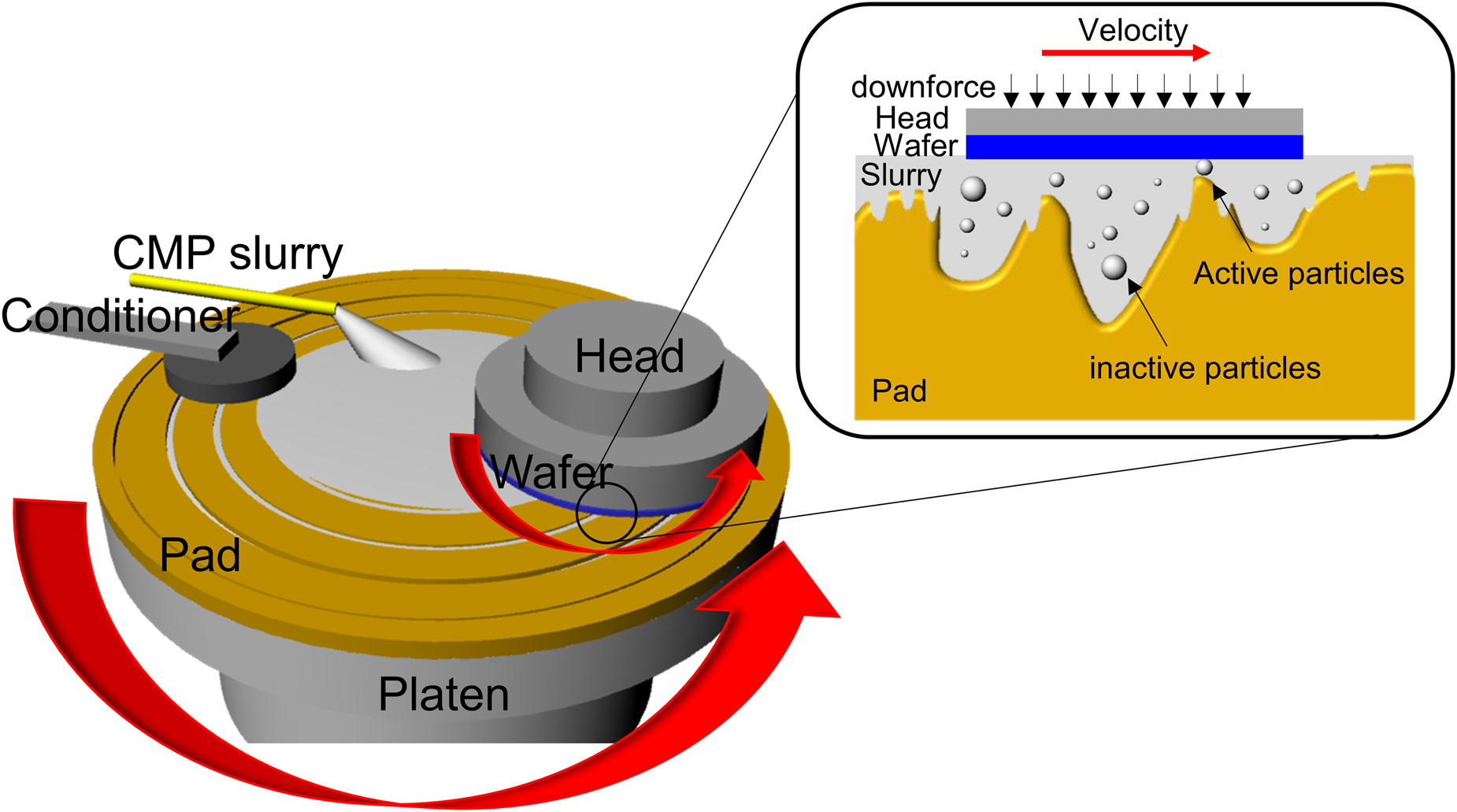
Figure 1: Schematic diagram of a typical CMP tool and three-body interactions occurring in the wafer/abrasive/pad contact region.
TABLE 1. Typical CMP slurry components.
This review presents and discusses the most significant advances with respect to chemical and mechanical phenomena at the wafer interface during CMP. Chemical and mechanical phenomena such as contact mechanics, lubrication models, the chemical reactions between slurry components and films being polished, electrochemical reactions, adsorption behavior and mechanisms, temperature effects, and their complex interactions will be discussed. Also, the final section provides an overview of recently developed real-time in situ techniques to study some of the phenomena that occur at the slurry/pad–wafer interface during polishing.
Models Based on Contact Mechanics
Material removal occurs when there is direct contact between an abrasive particle and wafer surface during polishing. Models based on contact mechanics were proposed to explain the mechanical aspects of the material removal mechanism. Assuming that all particles are involved in material removal, their contact area on the particle–wafer surface is given as A ∝ C 1/3 ⋅ d −1/3 where C is the concentration of the abrasive particles and d is the abrasive diameter [Reference Basim, Adler, Mahajan, Singh and Moudgil9]. However, only abrasive particles larger than the gap between the polishing pad and the wafer surface, termed as “active” particles, can contribute to material removal (Fig. 1) [Reference Luo and Dornfeld10]. Of course, a larger gap will result in less interaction between particles and wafer. Luo and Dornfeld assumed that only the plastic, but not elastic, deformation caused by the indentation of the active particles into the wafer surface results in material removal. They developed a mathematical model to predict the material removal rates considering the characteristics of the active abrasive particles (size, size distribution, and concentration), pad hardness, and CMP process conditions [Reference Luo and Dornfeld10, Reference Luo and Dornfeld11]. The real contact area (A r) at the wafer–particle interface considering pad asperities with a Greenwood–Williamson approach was proposed by Lee et al. [Reference Lee, Jeong and Dornfeld12], which can be expressed as A r = (f s/C)(R p/σp)1/2(PA w/E pw) where R p is the average radius of curvature of pad asperity, σp is the standard deviation of the pad asperity height, P is the applied pressure, A w is the nominal area of the wafer surface, E pw is the compose Young's modulus of the pad and the wafer, f s is the area density of up area of the grooved pad, and C is a constant in the range of 0.3–0.4. Lee et al. reported that the real contact area ratio (real contact area/nominal contact area) continued to decrease over the CMP process, leading to the deterioration in the material removal rates [Reference Lee, Lee, Jeong and Jeong13]. Park and Jeong suggested that a uniform roughness pad provided much higher removal rates due to the larger real contact area compared with a random roughness pad [Reference Park and Jeong14]. While it is very difficult to observe the in situ movements of active particles during polishing, the contact area of pad–wafer can be measured and has been considered as the real contact area in most cases.
Borucki has developed a tool to measure the real contact area of pad–wafer using the confocal microscopy and analyzed the contact image with digital image processing [Reference Borucki15]. Philipossian et al. investigated the real contact area of a pad with a wafer as a function of the process/tool conditions, pad conditioner, polishing pad, and their combinations [Reference Mu, Han, Sampurno, Zhuang and Philipossian16, Reference Mariscal, McAllister, Sampurno, Suarez, Borucki and Philipossian17]. They observed that a higher contact area of pad–wafer results in a higher material removal rate. Later, Lee measured the real contact area of the polishing pad using a home-built tool as a function of applied pressure and abrasive size and proposed a modified semi-empirical model to predict the removal rates of SiO2 films [Reference Lee18].
However, according to the classical contact mechanics, when the real contact area between pad and wafer increases, the real contact pressure decreases, leading to a decrease in the material removal rate. The opposite conclusion may be drawn from the properties of CMP consumables (slurry, films, polishing pad, conditioner, etc.), their characteristics, and CMP process conditions. More elaborate studies are needed to understand two opposing tendencies of material removal rates.
The classic equation for contact mechanics is Preston's equation [Reference Preston19] expressed as MRR = KPV where MRR is the material removal rate, K is Preston's coefficient, P is the applied pressure on the wafer surface, and V is the relative velocity between the wafer and the polishing pad. Preston's equation was very useful in explaining most of the removal rates of dielectric materials in the early stages of CMP technology. However, it assumes a linear relationship between pressure P and relative velocity V and hence, is unable to explain non-linear polishing behavior in actual CMP [Reference Fan, Boning and Babu20, Reference Tseng and Wang21]. Also, Preston's equation does not consider the properties of CMP consumables and their characteristics. As the CMP process becomes more and more complex, it has been difficult to predict CMP results and explain their mechanism by only Preston's equation. Today's contact mechanics for the CMP process not only consider the properties of CMP consumables and their characteristics but also simulate the fluid dynamics and process parameters, which provide more reliable information on the actual CMP mechanism [Reference Fan, Boning and Babu20].
Despite a number of such investigations, more fundamental studies are needed to investigate the in situ measurement of the real contact area of active particles at the slurry/pad–wafer interface during polishing, especially while considering SiO2 and CeO2 abrasive particles that have been typically used for CMP applications. Most previous models considered particle size and size distribution, where the particle shape was assumed to be spherical. Their type, hardness, shape, particle agglomeration, and chemical reactions between slurry and wafer surface have a significant influence on the material removal rates. These factors have to be taken into consideration in the mathematical model based solely on contact mechanics.
Lubrication Models
During polishing, CMP slurries are transported to grooved trenches, pores, and texture of a pad and improve hydrodynamic lubrication (Fig. 1). Sundararajan et al. proposed a lubrication model for slurry flow and a mass transport model for material removal by solving the Reynolds equation [Reference Sundararajan, Thakurta, Schwendeman, Murarka and Gill22]. According to their numerical results, a 40–60 μm slurry film between the wafer and the pad is expected at an applied pressure of 14 kPa and a linear velocity of 1.3 m/s. Slurry film thickness decreased to the range of 15–30 μm with higher applied pressure on the wafer. Lu et al. developed a dual emission ultraviolet (UV)-enhanced fluorescence technique using a dual-camera imaging system to measure the thickness of the slurry film between the pad and a BK-7 wafer and in situ monitored the average slurry film thickness during polishing [Reference Lu, Rogers, Manno, Philipossian, Anjur and Moinpour23].
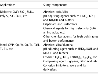
Philipossian's group modified this tool with high spatial resolution images, high-intensity UV laser pulses, and enhanced fluorescence [Fig. 2(a)] [Reference Gray, Apone, Rogers, Manno, Barns, Moinpour, Anjur and Philipossian24]. They used two different fluorescent dyes that can be excited at different wavelengths and recorded the fluorescence intensities of the dye molecules in the slurry using two high-resolution cameras. The intensity ratio of light detected by each camera was converted to slurry film thickness after proper calibration [Fig. 2(a)] [Reference Lu, Rogers, Manno, Philipossian, Anjur and Moinpour23, Reference Gray, Apone, Rogers, Manno, Barns, Moinpour, Anjur and Philipossian24]. They also studied the dependence of the slurry film thickness on the type of conditioner disk (design, kinematics, and pressure) [Reference Li, Lee, Borucki, Rogers, Kikuma, Rikita, Nagasawa and Philipossian26] and pad properties (asperities, roughness, and groove) [Reference Rosales-Yeomans, Lee, Suzuki and Philipossian25]. They measured the in situ coefficient of friction (COF) along with slurry film thickness. COF showed an inverse relationship with the average slurry film thickness. In thick and more viscous slurry films, the abrasive particles and the pad are less likely to interact with the wafer, resulting in a lower COF. The high viscosity of CMP slurries not only results in ineffective mass transport of reactants across the wafer and poor lubrication between the wafer and the pad but also restricts the movement of abrasive particles in the slurry.
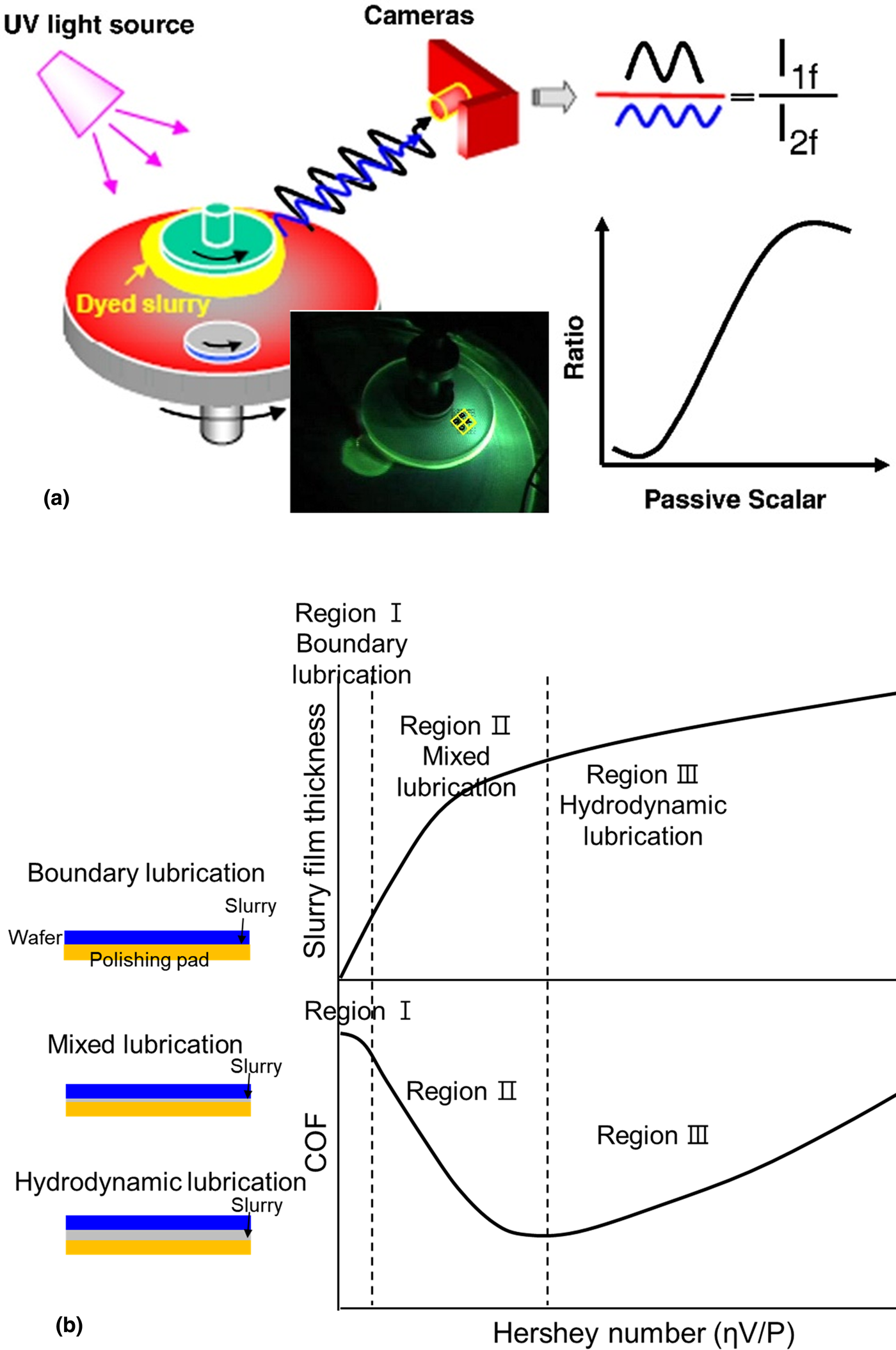
Figure 2: (a) Dual emission UV-enhanced fluorescence techniques with a dual-camera imaging system to in situ measure the thickness of the slurry film during polishing. Adapted from Ref. [Reference Rosales-Yeomans, Lee, Suzuki and Philipossian25], (b) COF and slurry film thickness plotted as a function of the Hershey number (ηV/P).
The relationship between COF and the slurry film thickness is well explained by the Stribeck curve [Fig. 2(b)] [Reference Stribeck27, Reference Jacobson28]. By plotting COF against the Hersey number [Reference Hersey29], three distinct regions—boundary lubrication, mixed lubrication, and hydrodynamic lubrication—were identified. The Hersey number is given by ηV/P where η is the slurry viscosity, V is the relative velocity between pad and wafer, and P is the pressure. Region I of this curve, known as boundary lubrication, shows relatively very high COF due to the direct contact between two solid surfaces. Region II is referred to as mixed lubrication where the wafer does not directly contact a pad because of the slurry film formed between the wafer and the pad. In Region III (hydrodynamic lubrication), the pad and the wafer are fully separated due to the relatively thick slurry film, resulting in a relatively low removal rate and COF.
Mullany and Byrne experimentally and theoretically investigated the effect of slurry film thickness on COF during Si wafer polishing in the mixed lubrication region [Reference Mullany and Byrne30], showing that the removal rates of the Si wafer decrease with increasing Hersey number. However, the traditional Stribeck curve fails to explain the lubrication phenomena, while COF and downforce fluctuated significantly during polishing because of the so-called stick-slip phenomena [Reference Han, Sampurno, Theng, Sudargho, Zhuang and Philipossian31, Reference Bahr, Sampurno, Han and Philipossian32]. Han et al. developed a Stribeck+ curve involving instantaneous process valuables [Reference Han, Sampurno, Theng, Sudargho, Zhuang and Philipossian31, Reference Bahr, Sampurno, Han and Philipossian32] (measured shear force and downforce, calculated, and recorded COF), instead of using a constant of shear force and downforce throughout the polishing process, and successfully explained the Stribeck+ curves for SiO2 [Reference Han, Sampurno, Theng, Sudargho, Zhuang and Philipossian31], Cu [Reference Bahr, Sampurno, Han and Philipossian32], and W CMP [Reference Bahr, Sampurno, Han and Philipossian32] using various combinations of CMP slurries and pads.
As mentioned earlier, viscosity is one of the key parameters that control the slurry film thickness and COF [Reference Stribeck27, Reference Jacobson28]. The Hersey number includes viscosity [Reference Hersey29], and it was considered as a constant during polishing because most CMP slurries behave as Newtonian fluids displaying a viscosity that is independent of shear rate. However, Lortz et al. found that the viscosity of silica slurries was constant, like Newtonian fluids, only up to a shear rate of 10,000 s−1 and increased significantly for higher shear rates in the range of 200,000–300,000 s−1 [Reference Lortz, Menzel, Brandes, Klaessig, Knothe and Shibasaki33]. Later, Crawford et al. developed a new methodology to in situ measure the rheological behavior of CMP slurries (in situ rheo-polishing setup) while polishing the wafer [Reference Crawford, Williams, Boldridge and Liberatore34]. They observed a fivefold increase in the viscosity of the silica slurries in the presence of 0.15 M KCl with increasing shear rate (≥10,000 s−1). Silica particles can easily form a network structure and agglomerate in an aqueous medium under high shear rates due to their strong hydrogen bonding, triggering a shear-thickening effect [Reference Raghavan and Khan35, Reference Khanna, Gupta, Kumar, Chang and Singh36, Reference Khanna, Gupta, Kumar, Chang and Singh37]. Moreover, in some cases, the heat generated by the chemical and mechanical interactions at the wafer–pad–particle interface can have a significant influence on the slurry viscosity [Reference Sorooshian, Ashwani, Choi, Moinpour, Oehler and Tregub38]. It usually decreases with increasing temperature. These changes in slurry viscosity should be reflected in the Stribeck curve.
Chemical Reactions Between Slurries and Dielectric Films
The mechanical effect alone is not sufficient to explain the material removal. Thus, it is essential to understand the chemical reactions of slurry components with the wafer surface during polishing. Since a glass-polishing model was first developed in the 1980s by Brown et al. [Reference Brown, Baker and Maney39], various theories and concepts have been proposed to explain the removal of materials during polishing. Cook [Reference Cook40] investigated the removal rates of glass using the slurries composed of various abrasive particles (e.g., alumina, silica, ceria, zirconia, and titania) and found that the ceria particles can interact with the glass surface by forming the strong chemical bonds, which he called as “chemical-tooth” [Fig. 3(a)] [Reference Laarz, Zhmud and Bergström41]. In the aqueous medium, the glass surface reacts with water molecules and forms dissolved silanol (Si(OH)4) as expressed by (SiO2)x + 2H2O ↔ (SiO2)x -1 + Si(OH)4 [Reference Iler42]. According to his model, OH groups on the ceria surface form strong Ce–O–Si bonds with silanol groups (–Si–OH/–Si–O−) on the glass surface during polishing [Fig. 3(a)]. The proposed chemical reaction is given by –Ce–OH + –Si–O− ↔ –Ce–O–Si– + OH− [Reference Iler42]. The Ce–O–Si bonds are much stronger than Si–O–Si bonds, which can be removed by both chemical reaction and mechanical abrasion during polishing. Later, Hoshino et al. [Reference Hoshino, Kurata, Terasaki and Susa43] suggested that SiO2 surfaces are removed as the form of lumps of Ce–O–Si bonds based on Fourier transform infrared spectroscopy (FTIR) and inductively coupled plasma atomic emission spectroscopy analysis of the post-CMP slurries [Fig. 3(a)]. Babu's group studied the effects of the Ce oxidation state (Ce3+/Ce4+) on the ceria surface on the interactions with SiO2 film using UV/visible spectroscopy and proposed that the surface Ce3+ sites stabilized by an oxygen vacancy are responsible for the high reactivity with SiO2 film [Fig. 3(a)] [Reference Dandu, Peethala and Babu44, Reference Dandu, Peethala, Amanapu and Babu45]. They also showed that the reactivity of ceria particles can be lowered by the blocking of the active Ce3+ surface sites using various additives [Reference Dandu, Peethala, Amanapu and Babu45, Reference Dandu, Devarapalli and Babu46]. Based on adsorption isotherms of silicate ions, Seo et al. reported that ceria particles with higher surface Ce3+ concentrations have higher adsorption affinity with SiO2 films. Taking advantage of these reports, current research for achieving high SiO2 removal rates is aimed at preparing Ce3+ rich ceria particles through either impurity metal-doping or coating. It is well known that lanthanide (La, Sm, Gd, Nd, and Yb) doping can increase Ce3+ concentration at the ceria surface, thus enhancing the SiO2 removal rates [Reference Cheng, Huang, Li, Wang, Xie and Lu47, Reference Praveen, Cho, Park and Ramanathan48]. Recently, Kim et al. have developed the core/shell type Ce3+ rich ceria abrasive for improved SiO2 removal rates [Reference Kim, Seo, Lee, Moon, Lee, Yi and Paik49]. Additionally, by coating the abrasives with a layer of different materials and chemical compositions, it is possible to change the physicochemical properties of the core abrasives and their reactivity with films [Reference Kim, Seo, Lee, Moon, Lee, Yi and Paik49].
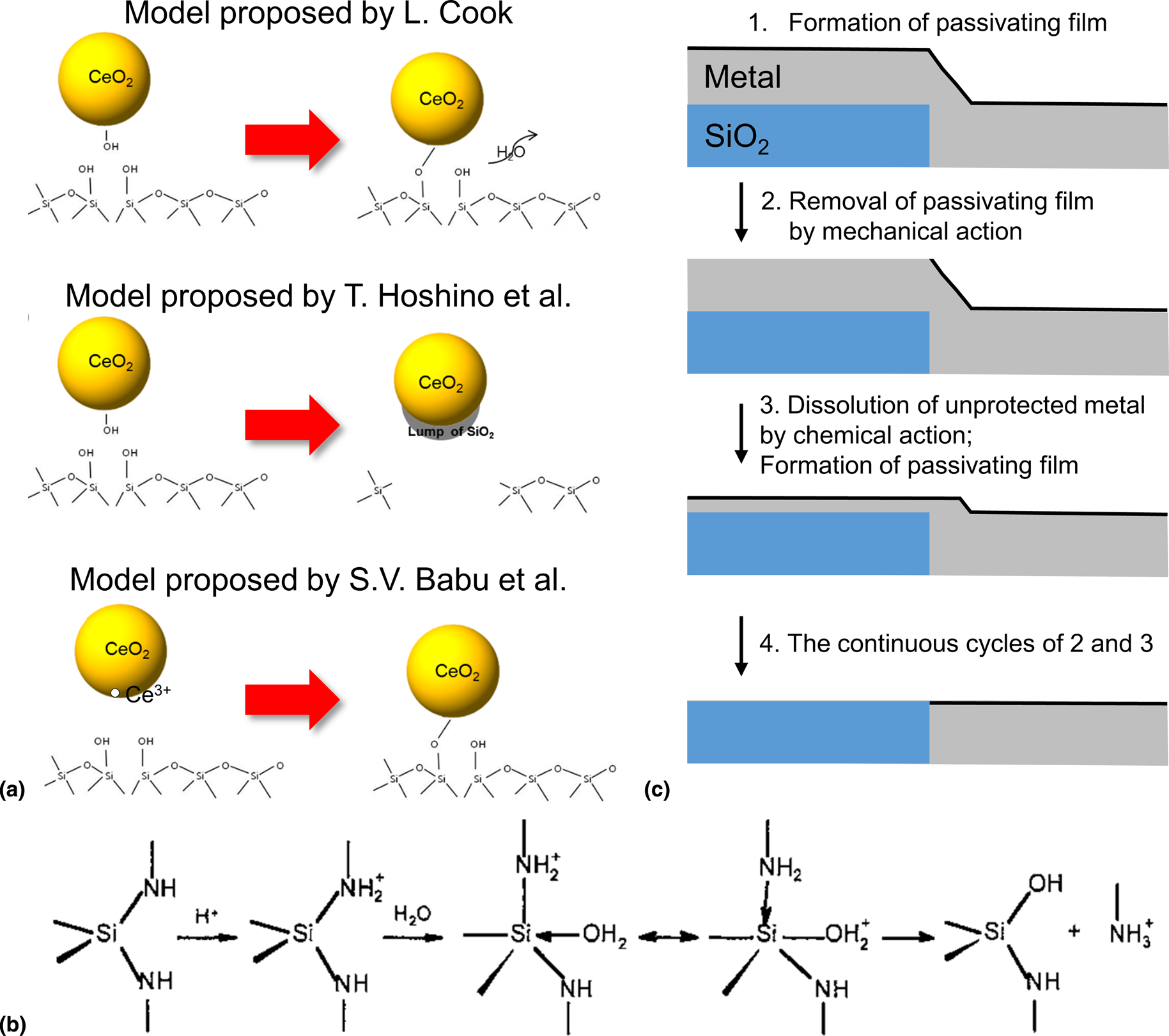
Figure 3: (a) Schematic illustration of SiO2 removal mechanisms and (b) Si3N4 hydrolysis reaction mechanism. Adapted from Ref. [Reference Laarz, Zhmud and Bergström41]. (c) Schematic diagram of the material removal mechanism.
Si3N4 films can be easily oxidized to SiO2 at the surface when exposed to water or air, and then removed, as in the case of SiO2 films, by chemical reaction (the formation of Ce–O–Si bonds) as well as mechanical abrasion [Reference Hu, Gutmann and Chow50]. Figure 3(b) shows the overall hydrolysis of Si3N4 film in an aqueous medium; an amine is liberated from Si3N4 film through nucleophilic attack of water molecules, with the overall reaction described as Si3N4 + 6H2O → 3SiO2 + 4NH3 (ΔG° = −147 kcal/mol at 298 K) [Reference Raider, Flitsch, Aboaf and Pliskin51]. The oxidized surface layer may be further hydrated as silicate species, which is written as ≡Si–O–Si ≡ + H2O → Si(OH)4. Laarz et al. [Reference Laarz, Zhmud and Bergström41] and Iler [Reference Iler52] showed that the rate of hydration is strongly affected by slurry pH, surface area, the preparation method of film, temperature, etc. Also, Laarz et al. found that the oxidized surface layer on Si3N4 film behaved like amorphous silica and determined the activation energy (52 kJ/mol) for the hydrolysis of the amorphous surface layer [Reference Laarz, Zhmud and Bergström41]. The conversion process/reaction of Si3N4 film is important in determining the removal mechanism of Si3N4, and its removal rate [Reference Hu, Gutmann and Chow50]. Babu and co-workers investigated various amino acids (alpha, cyclic, and aliphatic) that can be preferentially adsorbed onto Si3N4 film, inhibiting its hydrolysis to SiO2 [Reference America and Babu53, Reference Penta, Peethala, Amanapu, Melman and Babu54]. The details of the mechanism of Si3N4 removal rate suppression will be discussed in detail. Later, Alety et al. showed that the removal rate of Si3N4 film in the presence of 0.1 wt% ceria particles + 2.3 mM Ce(NO3)3 at pH 4 was ~300 nm/min, whereas it is ~10 nm/min with only ceria particle [Reference Alety, Sagi and Babu55]. X-ray photoelectron spectroscopy of the polished Si3N4 films is similar to that of an as-received silicon oxynitride film which led them to suggest that, in the presence of Ce3+, the surface of Si3N4 film can be converted to silicon oxynitride which was then polished at a high rate [Reference Alety, Sagi and Babu55].
Chemical Reactions Between Slurries and Metal Films
Unlike the removal mechanisms of SiO2 and Si3N4 films, metal films (W, Cu, Ru, Ta, and some of their alloys) are very difficult to be polished by only abrasive particles due to their inertness and hardness [Reference Krishnan, Nalaskowski and Cook1]. Kaufman et al. first proposed the polishing mechanism of W films when the slurry was composed of ferricyanide, hydrogen phosphate, and ethylenediamine [Reference Kaufman, Thompson, Broadie, Jaso, Guthrie, Pearson and Small56]. A “soft” passivating layer forms on the W film in the presence of ferricyanide ,[Fe(CN)6]3−,as an oxidizer, which can be written as W + 6[Fe(CN)6]3− + 4H2O → WO42− + 6[Fe(CN)6]4− + 8H+ [Reference Kaufman, Thompson, Broadie, Jaso, Guthrie, Pearson and Small56]. They proposed that the “soft” passivation layer can be easily removed by mechanical abrasion, and the fresh metal is exposed to the oxidizer again, which is subsequently passivated and then removed [Reference Kaufman, Thompson, Broadie, Jaso, Guthrie, Pearson and Small56]. Paul and co-workers proposed chemical kinetics of W [Reference Paul57] and Cu films [Reference Paul, Kaufman, Brusic, Zhang, Sun and Vacassy58] as a function of oxidizer, chelating agent, inhibitor, and mechanical contribution with a mechanical abrasion process. The passivation layer MC* forms on the metal film M in the presence of chemical component C by the chemical reaction; M + C ↔ MC*. The passivation layer can be partially dissolved in the slurries (Mbulk + MC* → MCaq + M) or removed by mechanical abrasion (MC* + A → MC–A + M) where MCaq is the dissolved species of MC, A is the abrasive particle, and MC–A is the leaving material from the metal surface. Kinetics of competitive reactions of film formation r f = k fN M[C] by oxidizer, film dissolution r d = k dN MC* by chelating agent, and mechanical abrasion r M = k M(N a/A)N MC* by particles determine the removal rates of the metal film where k f, k d, and k M are the rate constants for the reactions, N M and N MC* are the number of M and MC* sites on the metal M surface, [C] is the concentration of the chemical component C in the slurry and N a is the number of the active abrasive particles per unit area A of the metal surface. Later, Paul and Vacassy extended their model to the systems with inhibitor by combining the reaction and kinetics described above [Reference Paul and Vacassy59]. The mechanism of this process is used to explain other metal CMP processes, and the possible chemical reactions at the metal surface are summarized below [Reference Roy and Babu60, Reference Lee, Lee and Jeong61].
 $$\hskip-37pt {\rm Metal} + {\rm Oxidizer}\to {\rm Metal}\,{\rm oxide} + {\rm partially}\,{\rm dissolved}$$
 $$\hskip-21.9pt{& {\rm Metal}/{\rm Metal}\,{\rm oxide} + {\rm Chelating}\,{\rm agent}} \cr & \quad \to {\rm Formation}\,{\rm of}\,{\rm the}\,{\rm insoluble}\,{\rm passivating}\,{\rm layer}\,{\rm or} \cr &\quad {\rm Dissolved}\,{\rm complex}\,{\rm ion}}$$
 $$\eqalign\hskip-3pt{& {\rm Metal} + {\rm Inhibitor}\to {\rm Formation}\,{\rm of}\,{\rm the}\,{\rm insoluble}\,{\rm passivating}\,{\rm layer}}$$
 $$\hskip-100pt{\rm Metal} + {\rm H}^ + {/}{\rm O}{\rm H}^-\to {\rm Dissolved}\,{\rm as}\,{\rm M}^{{ n} + }$$
Various oxidizers such as H2O2, KIO3, Fe(NO3)3, K2S2O8, and their mixtures have been investigated [Reference Kaufman, Thompson, Broadie, Jaso, Guthrie, Pearson and Small56, Reference Seo, Kim, Lee, You, Moon, Lee and Paik62, Reference Du, Tamboli, Luo and Desai63, Reference Ranaweera, Baradanahalli, Popuri, Seo and Babu64]. H2O2 has been widely used as an oxidizer for many metal CMP slurries due to its low cost and powerful oxidizing capability [Reference Hong, Patri, Ramakrishnan, Roy and Babu65, Reference Hegde, Patri and Babu66]. When both ferric ions and H2O2 are present, ferric ions can lead to the decomposition of H2O2 into the free hydroxyl radicals (⋅OH), powerful oxidants, through the Fenton reaction. These radicals can rapidly form a “soft” passivation layer on the metal film, resulting in high MRR and improved topography of metal film [Reference Seo, Kim, Lee, You, Moon, Lee and Paik62, Reference Lim, Park and Park67]. Chelating agents such as glycine and citric acid that form a complex with metal ions can also help in the material removal by forming either insoluble or soluble surface complexes on the metal surface [Reference Aksu and Doyle68, Reference Popuri, Sagi, Alety, Peethala, Amanapu, Patlolla and Babu69]. However, corrosion defects such as pitting, cracking, and excessive etching will inevitably occur when the metal films are exposed to corrosive reagents [Reference Tseng and Babu70]. Organic inhibitors containing heteroatoms such as O, N, and S have been used to inhibit the corrosion of a metal. They can be effectively chemisorbed on the metal surface through the lone pair of electrons on these heteroatoms. Azole derivatives such as benzotriazole (BTAH, often referred to simply as BTA) and 1,2,4-triazole (TAZ) have been used as a corrosion inhibitor for the metal film during polishing, as discussed later in the section on the inhibitor.
The mechanism of the metal CMP process involving the continuous cycles of the formation of a passivating layer on the metal film by oxidizer and inhibitor, removal of the passivating layer by the mechanical action, dissolution by chemical reactions, and re-passivation of the metal film is shown in Fig. 3(c).
Electrochemical Reactions
Metal CMP is governed by electrochemical behaviors of metal films in the presence of oxidizer, complexing agents, and corrosion inhibitors. When exposed to slurry components, the metal film is oxidized and loses electron, forming metal cation (anodic reaction, M = M+ + e−) and the corresponding cathodic reduction reaction receives electrons (O2 + 4H+ + 4e− = 2H2O). Oxidation/dissolution and passivation of metal films occur at the open circuit potential (OCP) of each system [Reference Sulyma and Roy71]. The OCP transients stabilize when the anodic and cathodic sites arrive at a saturation point, and the OCPs and pH values of the slurries are used to predict the thermodynamically stable chemical compounds or species of a given metal film in the slurry components according to Pourbaix diagrams (or E-pH diagrams). The general E-pH-dependent reaction at 25 °C can be expressed as a(Ox) + mH+ + ne− ↔ b(Rd) + cH2O where a, m, b, and c are the number of molecules, n is the number of electrons involved in the reaction, and Ox and Rd denote the oxidized and reduced species of the active redox couple, respectively. E-pH diagrams were constructed by using the Nernst equation and appropriate equilibrium constant expressions [Reference Verink and Winston Revie72]: E = E 0–(2.303 RTm)/(nF)pH +(2.303 RT/nF)log(C Oxa/C Rdb) where E is the actual cell potential at nonstandard condition, E 0 is the standard reduction potential, R is the gas constant, T is the absolute temperature, F is the Faraday constant, and C Ox and C Rd represent the concentration of the species Ox and Rd involved in the E-pH-dependent reactions. Pourbaix diagrams for various metal–slurry systems for CMP applications have been developed [Reference Oliver73].
A goal of metal CMP is to uniformly polish the interconnection materials (Cu, Co, Al, W, etc.) and the barrier materials (Ta, TaN, Ti, TiN, Co, Ru, etc.) with the desired removal rates and selectivity while minimizing CMP-related defects such as localized pitting, dissolution, and galvanic corrosion, and stop on the oxide layer. The interconnection materials and the barrier materials are in physical contact, and the polishing slurry provides a conductive pathway between them. According to mixed potential theory, two metals with different potentials are polarized until they reach the same potential, forming a galvanic couple. The more noble metal becomes a cathode for the oxygen reduction reaction, and the less noble metal is corroded more rapidly through dissolution/oxidation while supplying electrons to the cathode, resulting in the preferential dissolution/corrosion of either interconnection material or barrier material by galvanic corrosion (Fig. 4) [Reference Oliver73]. Corrosion parameters (E corr, I corr, E g, and I g) obtained from Tafel extrapolations provide useful information on the oxidation–reduction reactions of metal films in the slurry. Chemical additives induce the shifts in the E corr and the I corr by the complex mechanism. An upward shift of Tafel curves can occur due to anodic corrosion/passivation or cathodic stimulation. A downward shift in Tafel plots is observed with the addition of the cathodic inhibitor by retarding the rate of oxygen transfer to the cathodic sites on the metal films. It is necessary to minimize the potential difference of the metal/barrier couple with low corrosion currents through a careful selection of oxidizer, complexing agent, corrosion inhibitor, and the slurry pH. Cu metal and Ru barrier act as the anode and cathode of the galvanic couple, respectively. Galvanic corrosion of Cu–Ru couple needs to be controlled through the selective prevention of cathodic reactions on Ru film, and/or increasing the potential of Cu by preferential anodic inhibition of Cu films. Peethala et al. [Reference Peethala, Roy and Babu74] proposed a silica-based slurry containing 5 mM BTA and 7 mM ascorbic acid at pH 9 in the presence of KIO4, as an oxidizer as selective anodic and cathodic corrosion inhibitors for Cu and Ru films, respectively. The mixed corrosion inhibitor system not only minimized the galvanic corrosion of Cu–Ru couple but also achieved a reasonable removal rate selectivity of Cu and Ru films. Chockalingam et al. [Reference Chockalingam, Lagudu and Babu75] showed that 2 mM BTA and 3 mM sucrose in the presence of KIO4 at pH 10 were able to suppress both anodic and cathodic reaction of Cu and Mn films by forming a passivation layer on the films, leading to minimizing the individual corrosion of films as well as their galvanic corrosion. Jiang et al. [Reference Jiang, He, Niu, Li and Luo76] showed that the combination of BTA and Pluronic® P103 in the presence of KIO4 at pH 9.5 formed a compact passivation layer, composed of Pluronic® P103 adsorbed on the Cu-BTA complex, resulting in the desired Cu removal rate ~200 Å/min with the negligible dissolution and excellent surface quality. This slurry composition was also very effective in the control of the removal rates of Cu, Ru, and low-k dielectric films and their selectivity, but the galvanic corrosion of Cu/Ru couple needed to be reduced for improved surface quality when Ru is used as the barrier layer.
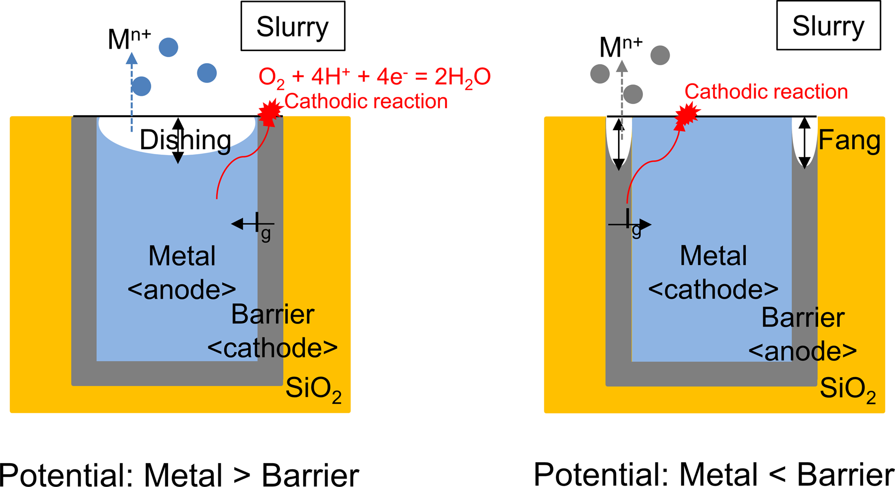
Figure 4: Galvanic corrosion of metal-barrier couple due to their potential difference. The preferential dissolution/corrosion of interconnection material and barrier material leads to the dishing and the fang, respectively.
Adsorption Behavior and Mechanism of Slurry Components on Abrasive Particles and Films
Organic compounds such as dispersants and passivation agents in CMP slurries have been used to stabilize the slurry and achieve the selective removal of the materials during polishing, respectively. The most common functional groups of dispersants and passivation agents used in CMP slurries are carboxylic acids (COOH) and amines (NH2). Chemical adsorption between the adsorbate and the surface occurs through various interactions such as electrostatic, hydrogen bonding, and hydrophobic interactions [Reference Farrokhpay77]. Electrostatic interaction is relevant for ionic species and involves the attractive electrostatic forces between opposite charges. Hydrogen bonding occurs when electronegative atoms such as O, S, or N approach a hydrogen atom bound to another electronegative atom. It is possible for organic compounds containing electronegative groups such as –OH, –O–, –NH, and –NH2 to adsorb onto -OH groups of the hydrated surface of particles and films through hydrogen bonding.
Adsorption Behavior and Mechanism of Dispersants on Abrasive Particles
Poly(acrylic acid) (PAA) and copolymers, anionic polymers, have been widely used as dispersants for ceria slurries [Reference Seo, Lee, Moon, Sigmund and Paik78, Reference Kim, Lee, Paik, Katoh and Park79]. When added to the slurry, the COOH groups of PAA are deprotonated to negatively charged COO− groups above its pKa of 4.5 and adsorb on the highly positively charged ceria surface (OH2+ sites) via electrostatic attractive interaction and hydrogen bonding [Fig. 5(a)] [Reference Hackley80], which increases electrostatic repulsion as well as steric hindrance between the ceria particles. PAA coated ceria particles are known to undergo transitions of bridging agglomeration-stable-flocculation depending on their physicochemical conditions such as pH, ionic strength, temperature, and concentration [Reference Sehgal, Lalatonne, Berret and Morvan81]. Citric acid and PAA have been used to disperse alumina abrasives [Reference Hidber, Graule and Gauckler82, Reference Ohtsuka, Mizutani, Satoshi, Asai, Kiguchi, Satone, Mori and Tsubaki83]. Song et al. suggested that the mixed dispersant system of citric acid and PAA was very useful for the stable dispersion of alumina abrasives, leading to higher Cu removal rates by suppressing the hydration of alumina abrasive [Reference Song, Lee, Lee and Koo84].
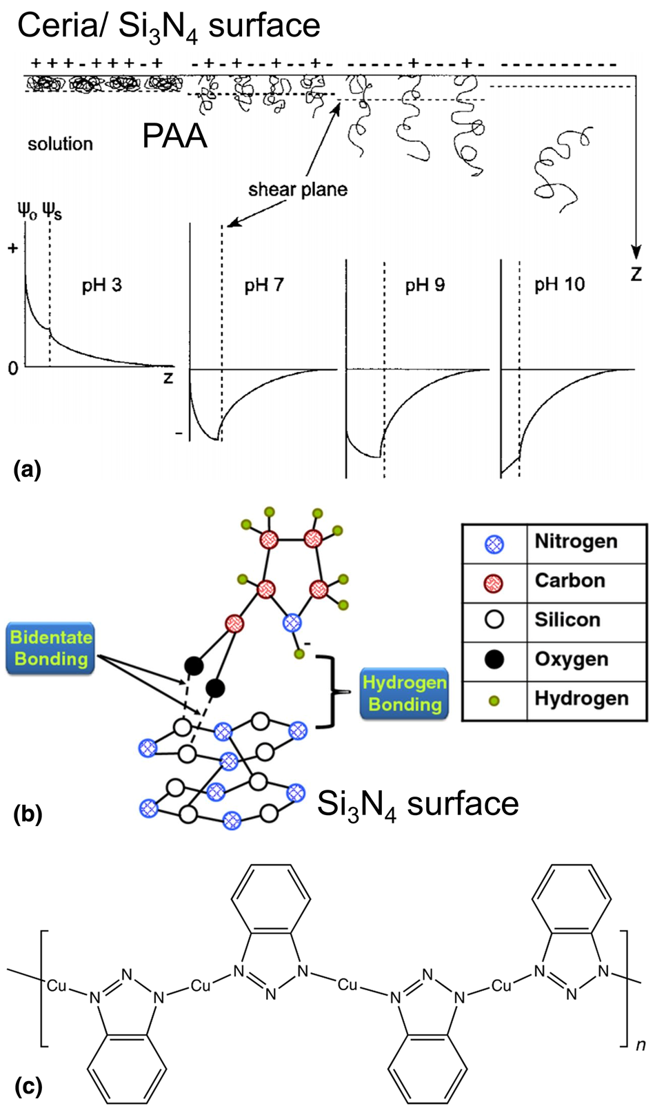
Figure 5: (a) Schematic illustration depicting PAA interactions at the ceria/Si3N4–slurry interface as a function of pH and corresponding potential-distance diagrams. Adapted from Ref. [Reference Hackley80]. (b) Bond formation between proline and silicon nitride surface. Adapted from Ref. [Reference America and Babu53]. (c) Cu-BTA complex chemisorbed on the Cu surface.
Ionic surfactants such as ammonium lauryl sulfate (ALS) and cetyl trimethyl ammonium bromide (CTAB) have been used in the formation of ceria slurries reported by Dylla-Spears et al. [Reference Dylla-Spears, Wong, Miller, Feit, Steele and Suratwala85]. They suggested that the formation of charged micelles above the critical micelle concentration may electro-sterically hinder the agglomeration of ceria particles, which is called the “charged micelle halo” stabilization mechanism [Reference Dylla-Spears, Wong, Miller, Feit, Steele and Suratwala85].
Tseng et al. [Reference Tseng, Kuo, Liao, Lu and Lin86] reported that the silica abrasives in the presence of methyl methacrylate were stabilized by either electrostatic barriers or steric barriers between the particles, resulting in an excellent uniformity of the oxide thickness across the wafer. Pan et al. [Reference Pan, Lu, Pan, Liu and Luo87] suggested that sodium dodecyl sulfate (SDS), an anionic surfactant, could improve the dispersion stability of silica-based slurries for Cu CMP. Indeed, free SDS surfactants remaining in the slurry were very useful to suppress Cu corrosion and lead to good surface quality. Polyethylenimine (PEI) and CTAB composed of the amine groups were used to disperse silica abrasive particles also [Reference Seo, Yoon, Moon, Kim, Sigmund and Paik88, Reference Basim, Vakarelski and Moudgil89]. They can be adsorbed onto the negatively charged silica through electrostatic attractive interaction as well as hydrogen bonding and prevent agglomeration. However, the adsorbed layer on the particle surface results in the low material removal rate by preventing particles from direct contact with the materials to be polished.
Adsorption Behavior and Mechanism of Passivation Agents on Films
PAA, when used as a passivation agent during polishing, can be preferentially adsorbed on the positively charged Si3N4 film (pHIEP ~5–7) through electrostatic attraction [Fig. 5(a)] [Reference Hackley80], suppressing the removal of Si3N4 film and yielding high selectivity [Reference Cho, Kim, Paik, Park and Sigmund90]. Kim et al. reported that PAA has almost ten times higher affinity with Si3N4 at pH 5–9 than with SiO2 [Reference Kim, So, Lee and Yang91]. The preferential adsorption of PAA on Si3N4 films was confirmed by attenuated total reflection (ATR)-FTIR spectra of SiO2 and Si3N4 surfaces treated with PAA. Kim et al. measured the thickness of adsorbed PAA on the Si3N4 film using atomic force microscopy as a function of ionic strength [Reference Kim, Lee, Lee, Paik and Park92]. The thickness of the adsorbed PAA layers on the Si3N4 film was 5.2, 4.5, and 3.8 nm with 0, 0.2, and 0.4 M KNO3, respectively. In some case, if the attractive forces such as hydrogen bonding are more dominant than the electrostatic repulsion between PAA and SiO2 film, it is possible for the adsorption of PAA to occur on the SiO2 film [Reference Kim, Jung, Yoon, Moon, Watanabe, Naito and Paik93].
Park et al. investigated the effect of adding both PAA and poly(vinyl pyrrolidone) (PVP) to ceria based slurries to achieve the multi-selectivity between SiO2, Si3N4, and poly-Si films and showed high selectivity (~65:~15:1 for SiO2:Si3N4:poly-Si films) in the presence of 0.05 wt% PAA and 0.2 wt% PVP in the pH range of 6.0–6.5 [Reference Park, Cui, Cho, Hwang, Hwang, Paik, Kang, Kwak and Park94]. Seo et al. proposed the PAA-poly(ethylene glycol) (PEG) “interpolymer complexes” as a passivation agent for high selectivity with low dishing and reported that the cross-linked network structure of interpolymer complexes significantly reduced dishing by preventing abrasives from polishing oxide in the trenches [Reference Seo, Moon, Moon and Paik95].
America and Babu [Reference America and Babu53] proposed that the COOH group of the amino acid proline can form a bidentate interaction with the Si–OH group on Si3N4 film along with H-bonding between the amino acid and Si3N4 film [Fig. 5(b)]. The bidentate bonding is observed where two or more hydrogen bonds are formed with a base or base pair. More generally, many amino acids were able to suppress the removal rates of Si3N4 film through the prevention of the hydrolysis of the Si3N4 as long as there are available in sufficient amounts during polishing. Since amino acids can also be adsorbed on the abrasive particles, free amino acids remaining in the solution must be of sufficient quantity for effective suppression of Si3N4 film removal rates. Since these amino acids are sensitive to a change of pH, the slurry pH needs to be optimized based on their pKa values [Reference Penta, Peethala, Amanapu, Melman and Babu54, Reference Penta, Amanapu and Babu96].
Hydrophobic interaction involves the adsorption of the nonpolar groups of organic molecules such as a hydrocarbon backbone (–CH2−CH2−) onto hydrophobic surfaces. Penta et al. [Reference Penta, Amanapu, Peethala and Babu97] investigated four different anionic surfactants and showed that these negatively charged surfactants could preferentially adsorb on positively charged Si3N4 film via electrostatic interactions. A monolayer of anionic surfactants is formed by electrostatic attraction between surfactants and Si3N4, followed by a secondary layer by hydrophobic interaction between the hydrophobic tails of anionic surfactants, suppressing Si3N4 removal rates. Nonionic surfactants that can preferentially adsorb on the hydrophobic poly-Si surface via hydrophobic interaction for preferential removal of SiO2 over poly-Si were studied by Lee et al. [Reference Lee, Park, Yoon, Han, Hah and Moon98], and there was a strong dependence of the selectivity on the hydrophilic–lipophilic balance value and molecular weight of nonionic surfactants.
Metal films are prone to dissolve when exposed to reactive components in the slurry, and corrosion inhibitors are added to prevent the corrosion defects such as pitting, cracking, and excessive etching during polishing. Most of the inhibitors studied for CMP applications are organic compounds containing N, S, and O atoms [Reference Aliofkhazraei99]. A metal cation can interact with aromatic rings containing conjugated bonds, π electrons, and lone-pair electrons from heteroatoms (O, N, or S). The efficiency of heteroatoms in the inhibitor molecules increases in the order of O < N < S. The corrosion inhibition of metal films involves either physisorption or chemisorption of the inhibitor on the metal surface. Electrostatic attractive force between the charged inhibitor molecules and the charged metal surface leads to physisorption. Chemisorption is due to the interaction between unshared electron pairs of the heteroatom and metal atoms to form coordinate covalent bonds. The standard adsorption free energy (ΔG°ads) can provide insight into the mechanism of corrosion inhibition. The ΔG°ads values above −20 kJ/mol and below −40 kJ/mol correspond to the physisorption and chemisorption process, respectively. Anodic inhibitors reduce the corrosion potential of metal films by oxidizing a surface layer and forming a thin passivating film on the metal. Cathodic inhibitors suppress the cathodic reaction (O2 + 2H2O + 4e− = 4OH−) by retarding the rate of oxygen transfer to the cathodic sites on the metal surface. Molecules with aliphatic chains are effective in suppressing the corrosion of metal films due to the attraction of nonpolar hydrophobic parts of inhibitor and polar medium [Reference Aliofkhazraei99]. The hydrophobic parts of inhibitors form a protective layer on the metal surface. Their size and molecular weight have an impact on the inhibition efficiency [Reference Malik, Hashim, Nabi, Al-Thabaiti and Khan100]. Larger the molecule, higher inhibition efficiency: R3N > R2NH > RNH2, where R is a hydrocarbon chain.
Azole derivatives such as BTA and TAZ have been widely used as corrosion inhibitors for metal films during polishing [Fig. 5(c)] [Reference Zhang, Liu, Wang, Niu, Ji, Du and Han101, Reference Mu, Zhong, Rushing, Li and Shipp102, Reference Yang, Zhang, Zhang, Wang, Yu, Wang and Liu103]. BTA can be adsorbed onto a Cu film by the coordination of the lone-pair electrons of the N atoms in BTA [Fig. 5(c)] with the Cu atoms on the surface [Reference Cotton104, Reference Xue, Ding, Lu and Dong105]. Xue et al. suggested that BTAH reacts with metallic Cu much faster than on Cu oxide and forms a polymeric passivating layer for Cu film than for copper oxides [Reference Xue, Ding, Lu and Dong105]. Also, they showed that Cu could be oxidized to Cu(I) in the presence of dissolved oxygen and form a Cu(I)BTA complex with BTA: 4Cu + 4BTAH + 2O2 ↔ Cu(I)BTA + 2H2O [Reference Xue, Ding, Lu and Dong105].
Although surfactants such as CTAB [Reference You, Seo, Kim and Song106], ammonium dodecyl sulfate [Reference Hong, Patri, Ramakrishnan, Roy and Babu65], and potassium oleate [Reference Popuri, Amanapu, Ranaweera, Baradanahalli and Babu107] were also investigated as corrosion inhibitors, BTA is the most common corrosion inhibitor used in CMP slurries. In any case, all these inhibitors can complex with metal ions and remain stable on the metal film as undesirable organic residues [Reference Cho, Shima, Hamada and Park108], and it has been very difficult to remove these organic residues during post-CMP cleaning [Reference Seo, Vegi, Ranaweera, Baradanahalli, Han, Koli and Babu109, Reference Seo, Vegi and Babu110]. So, post-CMP cleaning has become essential to remove these organic residues from the films while minimizing other defects (e.g., residual particles, foreign materials, scratches, and corrosion). Figure 6 shows a summary of the adsorption of organic compounds such as dispersants, passivation agents, and inhibitors on the abrasive particles and the wafer surfaces in the CMP system.
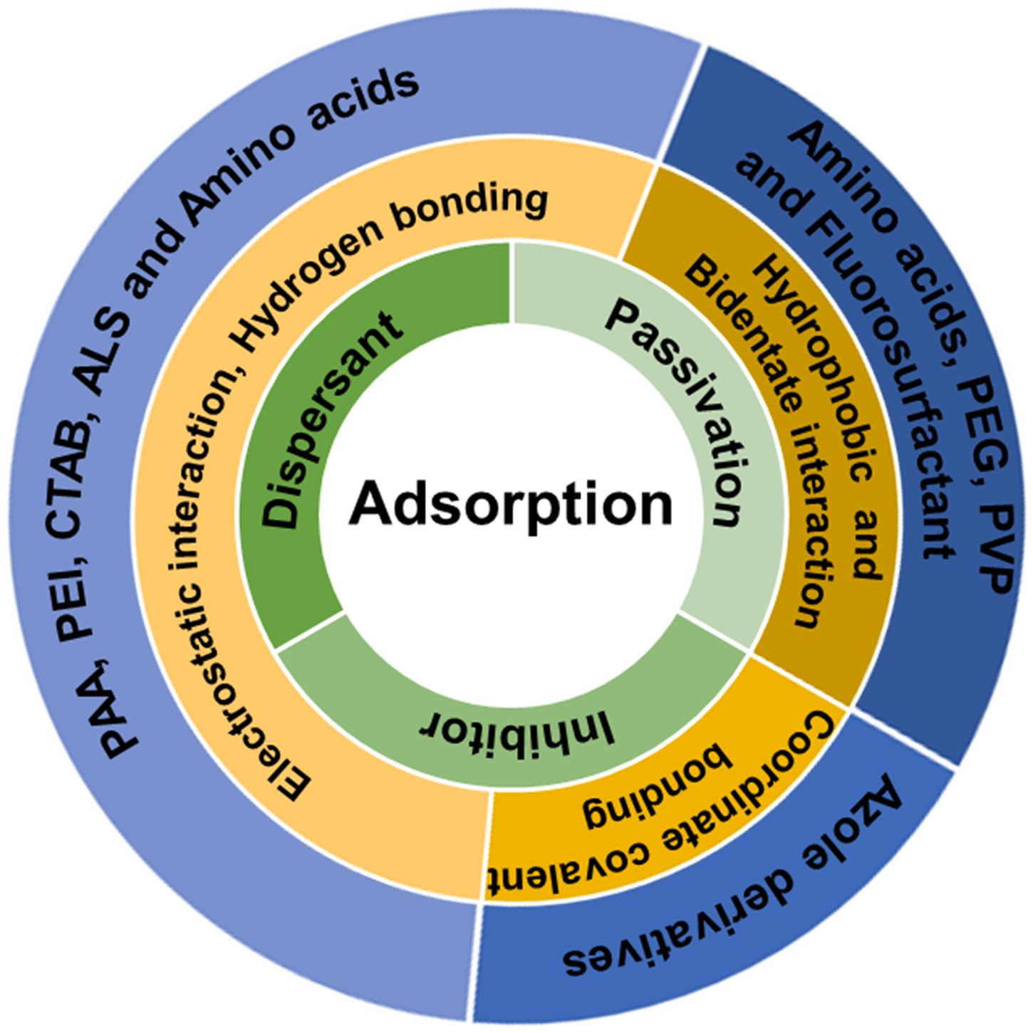
Figure 6: An overview of the adsorption of organic compounds such as dispersants, passivation agents, and inhibitors on the abrasive particles and the wafer surfaces.
Temperature Effects
The major sources of thermal heating during polishing are frictional dissipation and the chemical reactions of slurry components at the slurry/pad–wafer interface, leading to a change in temperature. Various thermal models of the polishing process based on kinematics [Reference Hocheng, Huang and Chen111], energy generation [Reference White, Melvin and Boning112], and a combination of frictional heating and chemical reactivity [Reference Oh and Seok113] were proposed. Infrared thermography was used to characterize the impact of thermal effects on pad life, polishing rate, and non-uniformity during polishing. Wang et al. [Reference Wang, Liu, Feng and Tseng114] reported that the exothermic reaction between the metal surface and the oxidizers in the acidic environment could increase the temperature up to 75 °C during polishing depending on CMP conditions, which was lowered by the slurry flow. White et al. [Reference White, Melvin and Boning112] proposed an energy flow mechanism into and out of the process, and an energy balance was used to predict an increase in the slurry temperature during polishing. They suggested that the heat is generated by the mechanical abrasion and the chemical reactions associated with the slurry chemistry and enthalpy is primarily transferred into the polishing pad, and then, most of the heat will be removed by convection of slurry flow, conduction, and radiation to the environment [Reference White, Melvin and Boning112]. Oh and Seok [Reference Oh and Seok113] suggested that frictional heat generated during polishing is transferred to the wafer, pad, and slurry, and plays a key role in accelerating the chemical reactions at the slurry/pad–wafer interface. Their theoretical results showed that the temperature variation of the wafer, pad, and slurry has an influence on material removal rates. Indeed, the temperature rise of the CMP process not only has an effect on the slurry viscosity, pH, particle size, and zeta-potential [Reference Mullany and Byrne30, Reference Kim, Kim, Jeong, Lee and Shin115, Reference Kim, Seo and Lee116] but also leads to delamination or peel-off of the metal films [Reference Tseng and Babu70, Reference Kakireddy117]. For example, a 5 °C change in temperature can lead to a 10% drop in slurry viscosity [Reference Mullany and Byrne30]. Kakireddy reported that thin Cu film peeled off during polishing at higher temperatures due to lower adhesion and mechanical strength [Reference Kakireddy117].
The Effect of Temperature Changes on the Chemical and Mechanical Reactions during Polishing
As stated earlier, the scope of this review paper is limited to CMP slurries and related to chemical and mechanical aspects of the CMP process, although other CMP consumables such as pad, pad conditioner, wafer carrier, and retaining ring and CMP conditions need to be considered. Figure 7 shows a simplified scheme of the complex interactions between chemical and mechanical aspects of the CMP process discussed in this review paper. It is important to emphasize that Fig. 7 helps in understanding the complex interactions between chemical and mechanical effects that occur at the pad–wafer–particle interface during polishing.
(i) Case I: The materials or wafers are removed by the synergetic effects of chemical and mechanical interaction during polishing. The energy dissipation due to frictional heating is responsible for increases in the temperaturesd during polishing. The average temperature of slurry increased up to 75 °C during the W CMP process, and Wang et al. suggested that the oxidation of W film causes the temperature increase because this reaction is exothermic [Reference Wang, Liu, Feng and Tseng114]. Also, in some cases, chemical reactions like the Fenton reaction are spontaneous exothermic processes, contribute to temperature increase during polishing.
(ii) Case II: As is well known, with increasing temperature of the system, the rates of chemical reactions increase [Reference Seo, You, Moon, Kim and Paik118], leading to higher removal rates [Reference Kim, Seo and Lee116, Reference Kim, Ko, Seo and Lee119, Reference Mudhivarthi, Zantye, Kumar, Kumar, Beerbom and Schlaf120]. Kim et al. reported that the slurries at higher temperatures lead to the formation of the soft layers on the surface of SiO2 film, and this layer could be easily removed by mechanical abrasion [Reference Kim, Seo and Lee116, Reference Kim, Ko, Seo and Lee119]. Mudhivarthi et al. found that an increase in the surface oxidation/dissolution rate of Cu film, resulting in higher Cu removal rates [Reference Mudhivarthi, Zantye, Kumar, Kumar, Beerbom and Schlaf120]. The corrosion rate of metal films increases with increasing the temperature, leading to a decrease in the inhibition efficiency.
Moreover, an increase in temperature not only leads to changes in the polymer chain conformation (coiled transformed to stretched) [Reference Wiśniewska121] but also causes changes in the zeta-potentials and the pHIEP of abrasive particles and films [Reference Evenhuis, Guijt, Macka, Marriott and Haddad122], which have an influence on the adsorbed amounts and thickness of dispersants and passivation agents.
(iii) Case III: Since the formation of hydrogen ions and hydroxide ions from water (H2O ↔ H++OH−) is an endothermic process, the water dissociates to H+ and OH− as the temperature increases. The slurry pH decreases with increasing H+ concentration at a higher temperature. Kim et al. reported that the change (ΔpH) in the pH of silica and ceria slurries as the temperature increased from 20 to 90 °C was ~1.0 and ~1.3, respectively [Reference Kim, Seo and Lee116, Reference Kim, Ko, Seo and Lee119]. It is well known that a change in pH of slurry has a significant influence on the particle–wafer interactions [Reference Abiade, Choi and Singh123, Reference Seo, Gowda, Khajornrungruang, Hamada, Song and Babu124].
Also, the solubility of oxygen in water decreases with increasing temperature [Reference Montgomery, Thom and Cockburn125]. For example, 10.07 mg/L of oxygen can be dissolved in the water at 15 °C, while 7.54 mg/L of oxygen can be dissolved in the water at 30 °C [Reference Montgomery, Thom and Cockburn125]. The change in the dissolved oxygen concentrations can affect the oxidation and dissolution process of metal films and the surface chemistry of abrasive particles as well as their mutual interactions [Reference Srinivasan, Dandu and Babu3].
(iv) Case IV: The hydrodynamic size (R h) of abrasive particles can be determined by the Stokes–Einstein relation; R h = kT/6πηD where k, T, η, and D represent Boltzmann's constant, temperature, water viscosity, and the diffusion coefficient. Since the equation includes the viscosity of the fluid medium (in our case, water) and the temperature, both parameters strongly influence on the hydrodynamic size of particles. Indeed, the viscosity of the water η decreases with increasing temperature (Case V) [Reference Korson, Drost-Hansen and Millero126]. Zeta potentials of the abrasive particles increase with temperature. Zeta potentials of particles can be obtained indirectly from the measurement of the electrophoretic mobility according to Henry's equation; U E = 2εζF(κa)/3η where U E is the electrophoretic mobility, ε is the relative permittivity of water, and F(κa) is Henry's function (dimensionless). For particles in an aqueous medium, F(κa) is 1.5 according to the Smoluchowski approximation. The variation of zeta potential of abrasive particles with temperature is explained by the known temperature dependence of the viscosity (η) and the relative permittivity (ε) of water. Evenhuis et al. reported that experimentally determined values of zeta-potential were directly proportional to the temperature [Reference Evenhuis, Guijt, Macka, Marriott and Haddad122]. Kim et al. also showed an increase in the zeta-potentials of commercial ceria slurries with increasing slurry temperatures [Reference Kim, Seo and Lee116]. It may be possible for the number of active particles that participate in material removal during polishing to be changed depending on the particle size and zeta potentials of the abrasive particles.
(v) Case V, VI, and VII: The viscosity of the slurry is a measure of its resistance to deformation by shear forces. High slurry viscosity impedes the transport of the slurry components across the wafer surface. As the temperature of liquid increases, the viscosity of slurry decreases (Case V), and the reactant molecules move faster (Case VI). Also, according to the Stribeck curve [Fig. 2(b)] [Reference Stribeck27, Reference Jacobson28], a decrease in the slurry viscosity at a higher temperature may allow the direct contact between two solid films with a thin slurry film thickness resulting in an increase in COF during polishing.
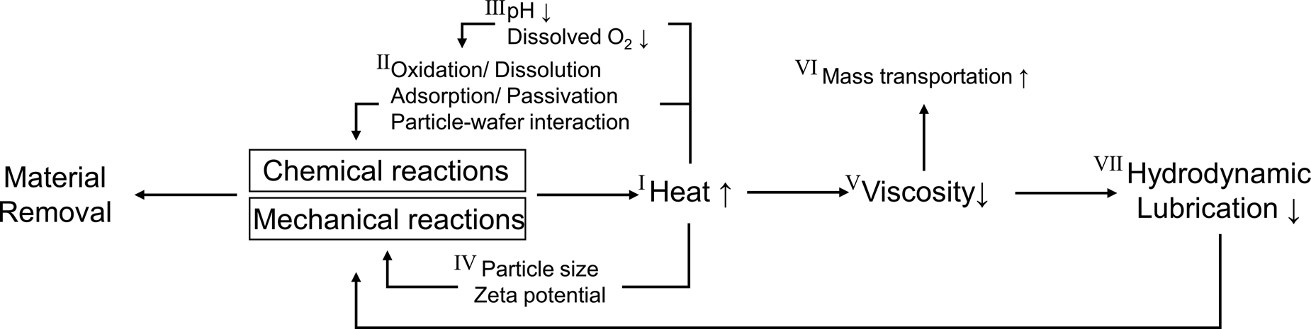
Figure 7: Schematic representation of the complex interactions between chemical and mechanical effects in the actual CMP system.
In Situ Techniques to Study the Phenomena that Occur at the Slurry/pad–wafer Interface during Polishing
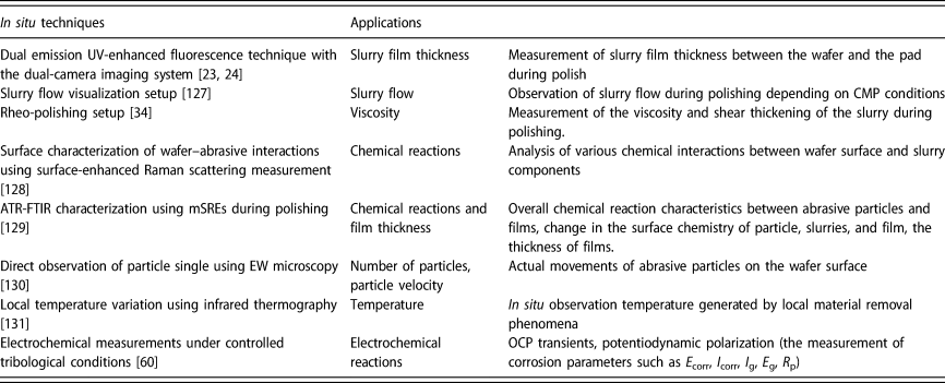
Research in the field of CMP has significantly increased, as the semiconductor industry grows. Numerous experimental techniques have been employed to understand particle–film–wafer interactions, but they are not adapted for in situ and real-time detection during polishing due to their dimensions and operating requirements. The actual CMP system includes the mutual interactions between chemical and mechanical effects. In situ measurement data collected during polishing are likely to provide more important insights into the underlying mechanisms of various complex reactions that occur at the slurry/pad–wafer interface. This section offers an overview of advances in the research and developments of in situ measurement studies in CMP systems and then discusses the challenges associated with these measurements. Table 2 presents a summary of in situ measurements applied in CMP systems while highlighting the main applications for each technique.
TABLE 2. Summary of in situ techniques studies in CMP systems.
Slurry film thickness was in situ monitored by analyzing the fluorescence intensities of the two different dye molecules in the slurry using a dual emission UV-enhanced fluorescence technique with a dual-camera imaging system [Fig. 2(a); Table 2] as described in the Hydrodynamic lubrication section [Reference Lu, Rogers, Manno, Philipossian, Anjur and Moinpour23, Reference Gray, Apone, Rogers, Manno, Barns, Moinpour, Anjur and Philipossian24]. Mueller et al. [Reference Mueller, Rogers, Manno, White and Moinpour127] used tracer particles to study fluid flow characteristics over pad asperities and recorded a video at 30 frames/s using high definition camera to obtain in situ slurry fluid flow data during polishing (Table 2) and manually analyzed the qualitative information of the slurry flow characteristics from the video. This tool and method enable to study wafer-scale slurry flow visualization depending on CMP conditions, slurry injection locations, and various pad types [Reference Mueller, Rogers, Manno, White and Moinpour127]. The studies that used dyes or tracer particles contain valuable information on slurry film thickness and flow characteristics [Reference Lu, Rogers, Manno, Philipossian, Anjur and Moinpour23, Reference Gray, Apone, Rogers, Manno, Barns, Moinpour, Anjur and Philipossian24, Reference Mueller, Rogers, Manno, White and Moinpour127]. However, these particles added to the slurry may not only have a significant influence on the chemical and mechanical reactions during polishing but also become embedded in the pad due to the hydrophobic interactions [Reference Mueller, Rogers, Manno, White and Moinpour127]. Moreover, the materials to be polished are limited to transparent glasses over UV and visible regions.
In situ rheo-polishing setup with a parallel-plate geometry was developed by Crawford et al. [Fig. 8(a); Table 2] [Reference Crawford, Williams, Boldridge and Liberatore34]. The top was constructed of a disposable plate, while a 2-in diameter SiO2 blanket wafer was inserted into the fixture housing with 2 mL of slurry. The gap between the top plate and the wafer surface was 30 μm, which allowed for shear rates up to 200,000 s−1. In some cases, shear-induced aggregation of particles, less than 2% of the total number of particles, was found at a high shear rate (≥10,000 s−1). Shear thickened samples generated about seven times more scratches on the wafer surface than non-thickened slurries. However, as they mentioned, this method not only has no applied normal force but also is incapable of measuring the real changes in slurry viscosity with rolling friction [Reference Crawford, Williams, Boldridge and Liberatore34].
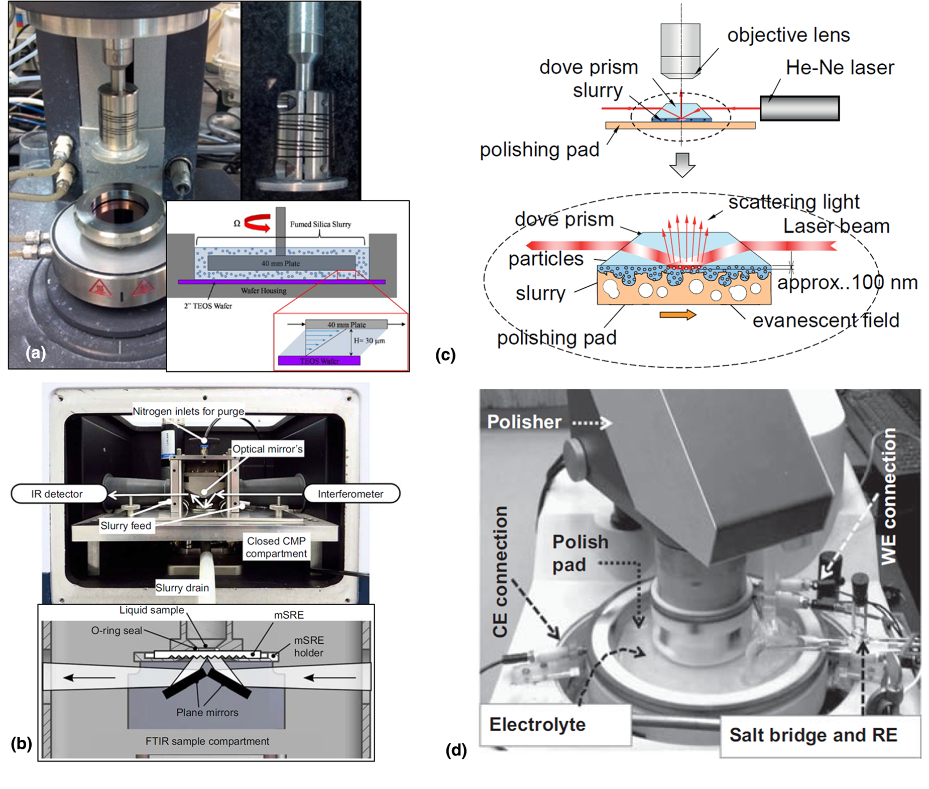
Figure 8: (a) Rheo-polishing setup with plate fixture and 40 mm upper plate, and schematic of the cross-sectional view of the rheometer plate and tetraethyl orthosilicate (TEOS) wafer covered with CMP slurry. Adapted from Ref. [Reference Crawford, Williams, Boldridge and Liberatore34]. (b) CMP-ATR accessory with mSRE placed in the sample compartment of a FTIR spectrometer. Adapted from Ref. [Reference Künzelmann, Schumacher and Babu129]. (c) Direct observation of particle single using total internal reflection fluorescence. Adapted from Ref. [Reference Kimura, Suzuki and Khajornrungruang130]. (d) A three-electrode setup used for electrochemical studies of metal films during polishing. Adapted from Ref. [Reference Roy and Babu60].
Takaya et al. have developed a custom-built Raman spectrometer to study various interactions of Cu-abrasive, abrasive-peroxide, BTA-peroxide, and BTA-abrasive-peroxide (Table 2) [Reference Takaya, Michihata, Hayashi, Murai and Kano128]. The surface-enhanced Raman scattering (SERS) system is an amplification technique that enhances Raman signal from molecules adsorbed on rough metal surfaces. 25 nm thick Cu film deposited on 10 mm glass was used as a substrate for SERS measurements, and it is immersed in the glass cell filled with the slurry. Their SERS analysis results for BTA-abrasive-peroxide suggested that both Cu-BTA and Cu(II)-fullerenol-complex layers are formed on the Cu surface simultaneously, and these layers may inhibit the further interactions of chelating agents and oxidizer with Cu film [Reference Takaya, Michihata, Hayashi, Murai and Kano128]. However, this method is also limited to only chemical reactions without mechanical effects. Since the actual metal polishing system includes the kinetics of competitive reactions between oxidizer, chelating agent, and inhibitor when the passivating layers were removed by mechanical abrasion, mechanical abrasion and slurry flow system, which need to be considered to get more realistic results.
The ATR-FTIR technique for the in situ characterization of CMP using micro-structured single reflection elements (mSREs) was developed by U. Künzelmann and H. Schumacher (Table 2) [Reference Künzelmann, Schumacher and Babu129]. They fabricated the microstructure, consists of a periodic array of V-shaped grooves on the backside of a double-side polished 4-in Si wafer with 525 μm thickness by wet etch in hot KOH solution, which is mSRE. This element not only enables to provide single reflection ATR measurement without any collimation but also covers the entire mid-infrared region with a high optical throughput due to the short light path [Reference Künzelmann, Schumacher and Babu129]. The coupling structures of the mSRE face downwards, and the pad is pressed from its upper side and rotated against the static mSRE, while the slurry was injected between at the wafer–pad interface. With the depth around 1 μm, this technique enables to an in situ analysis of the deposition, etching, and surface modification of wafer, pad, and abrasives during polishing [Reference Künzelmann, Schumacher and Babu129]. In situ ATR-FTIR spectra of the actual CMP system are very complex and thus result in the overlapping absorptions between the main components such as a wafer, pad, and abrasives, which is a major challenge to be addressed by researchers.
Kimura et al. showed that the movement of the particles located at the glass–pad interface could be imaged in situ using evanescent wave (EW) microscopy [Fig. 8(b); Table 2] [Reference Kimura, Suzuki and Khajornrungruang130]. EW microscopy, also known as total internal reflection microscopy, coupled with video microscopy was employed to follow the movements of particles near the glass–pad interface. In their experimental setup, an EW was generated when the laser light beam having 30 mW power at 632 nm wavelength (He–Ne laser) undergoes total internal reflection at a glass–slurry interface and propagated parallel to the surface with an exponentially decaying intensity [Reference Kimura, Suzuki and Khajornrungruang130]. The EW illuminates the particles present in the slurry and has a penetration depth (~100 nm) in an imaged area of 480 × 640 mm2. The frame rate of the digital high-speed video camera was 60 frames/s (fps). They suggested that the abrasive particles adhered to the Si(OH)4 layer on the SiO2 film were removed by slurry flow, which yields the material removal. They also reported that the actual contact area between the pad and the wafer is less than 2%, and suggested that the significant material removal is caused due to the non-contact lubrication effect [Reference Kimura, Khajornrungruang, Suzuki and Okamoto132]. Since Kimura et al. showed a home-built EW imaging system coupled with polishing setup, many research groups have developed different methods to monitor in situ and in real-time the interactions between particle, pad, and wafer during post-CMP cleaning as well as polishing [Reference Terayama, Khajornrungruang, Suzuki, Kusatsu, Hamada, Wada and Hiyama133, Reference Shima, Hamada, Wada, Takatoh and Fukunaga134]. Abrasive particles move far away rapidly from the glass surface by the slurry flow and the platen rotation and sometimes disappear from the field of view, preventing long-term particle tracking in the EW field. Moreover, the smaller particles, less than 100 nm particles used in the actual CMP system, scatter less light making them more challenging to detect using EW microscopy [Reference Khajornrungruang, Korkmaz, Angshuman, Suzuki, Kimura and Babu135]. Thus, more light needs to be collected by the objective lens to make the imaging of smaller particles possible.
Local material removal phenomena were in situ observed by infrared thermography (Table 2) [Reference Suzuki, Misono, Shamoto, Goto, Yasuda and Mochizuki131]. Frictional heating is responsible for increases in the temperature during polishing. Data were obtained from an infrared image sensor with the infrared light collected through a small hole fabricated on the wafer carrier during polishing. An increase in the temperature is related to material removal efficiency. The feasibility of the in situ observation of the polishing efficiency was confirmed by the polishing experiment with a polishing pad. According to Isobe's polishing model [Reference Isobe, Akaji and Kurokawa136], they suggested that the in situ detection of instantaneous temperature variations depending on Feret's diameters of the contact area between the pad and the wafer, leading to higher material removal rate [Reference Suzuki, Misono, Shamoto, Goto, Yasuda and Mochizuki131]. As they mentioned, it is very difficult to directly measure the change in the temperature at the particle–wafer–pad interface due to the limitation of the proposed method. Also, the system needs to apply fresh slurry to the pad–wafer interface and remove warm slurry after polishing that passed under the carrier to avoid heat accumulation.
Roy's group reported an electrochemical measurement coupled with a Struers Benchtop Polisher [Reference Roy and Babu60]. The top part of the system contains a 1-in diameter coupon wafer as a working electrode embedded in a Teflon holder attached to the polishing head. And the bottom part is a Teflon container attached to the platen. Electrical connection to the working electrode and the counter electrode was made through carbon brushes pressed against Cu ring surrounding Teflon holder (Top) and Teflon container (bottom), respectively. The reference electrode equipped with a salt bridge connects to the electrolyte. This system enables to in situ measure OCP transients and potentiodynamic polarization for the metal film under controlled tribological conditions. Roy's group demonstrated that the tribology and mechanical abrasion affects various catalytic reactions of Cu, Ru, Ta, and Co surfaces during polishing by evaluating CMP systems in the tribo-electrochemical approach [Reference Roy and Babu60, Reference Shi, Simpson and Roy137, Reference Turk, Shi, Gonyer and Roy138].
In situ measurements are taken in real-time during polishing and can be interpreted immediately. Moreover, in situ measurements can give more representative information of CMP slurry characteristics, including various chemical and mechanical actions that occur at the slurry/pad–wafer interface during polishing when compared with the ex situ analysis of CMP slurries. However, as stated above, there are still several limitations that need to be addressed. Additional studies and in situ techniques will be helpful to understand the underlying mechanism taking place during the CMP process.
Challenges and Future Directions
(i) Development of CMP slurries for new materials and integration schemes: As the scaling of the device dimensions runs into physical limitations, 3D integration, 3D NAND technology, and FinFET structure were employed by using new materials and processes [Reference Choe139, Reference Vegunta140]. As the architectures have changed from 2D planar to 3D vertical, new CMP steps involving new materials and complex 3D structures were proposed. Successful implementation of these schemes required developing novel CMP slurries and other consumables to achieve a range of tunable polish rates for new materials based on their characteristics such as stoichiometry, surface chemistry, hardness, chemical inertness or sensitivity, and thickness. A systematic and effective approach needs to be adopted to achieve the necessary high polishing performance, selective polishing, high planarity, low defects, etc. The research strategies, suggested by the author, for developing next-generation CMP slurries, are summarized in Fig. 9.
(ii) Defect reduction and post-CMP cleaning: Devices at 7 nm node and beyond present even more stringent requirements for the level of acceptable defectivity during the CMP process. The processes become more defect sensitive and require more expensive metrology techniques with appropriate optical resolution to detect the smaller defects. CMP-induced defects caused by residual particles, foreign materials, scratches, corrosion, etc. should be avoided during polishing. Since this is not always possible, post-CMP cleaning has become a crucial step to eliminate many of these defects [Reference Seo, Gowda and Babu141, Reference Gowda, Seo, Ranaweera and Babu142, Reference Hong, Niu, Liu, He, Zhang, Wang, Han, Yan and Zhang143, Reference Alety, Lagudu, Popuri, Patlolla, Surisetty and Babu144]. Recently, the author not only showed that the rupture of a strong chemical bonding between abrasive particles and the SiO2 films via a nucleophilic attack could help remove the particles from the surface [Reference Seo, Gowda and Babu141] but also reported a stability constant-based strategy to study reagents that can remove Cu-BTA and Co-BTA complexes from various surfaces (Cu, Co, TaN, and SiO2 films) [Reference Seo, Vegi, Ranaweera, Baradanahalli, Han, Koli and Babu109, Reference Seo, Vegi and Babu110]. Fundamental understanding of the formation and characterization of various types of CMP-induced defects will immensely benefit the development of next-generation CMP slurries and post-CMP cleaning solutions.
(iii) Development of environmentally friendly CMP slurries: Azoles such as BTA and TAZ are not only poorly biodegradable under wastewater treatment conditions but also lead to watermarks on the wafer surfaces and contamination of various surfaces under CMP conditions. The effluent wastewater from a semiconductor fabrication plant may contain high concentrations of azoles, etc., and will be challenging for wastewater treatment processes. Hence, the chemical additives that effectively passivate metal surfaces and exhibit sufficiently high biodegradation rates need to be considered keeping their environmental impact in mind.
(iv) Toxicity issues and safety considerations [Reference Babu145, Reference Ong, Teugels and Babu146] Toxic gases (e.g., PH3, AsH3) and the As containing waste slurries can be generated during the polishing of III–V materials such as GaAs, InGaAs, InAs, and InP. Hence, the goal of the polishing of III–V materials should be achieving high planarity without generating toxic by-products. In the acidic pH, Ru film can be converted to highly volatile RuO4, a toxic gas. The addition of complexing agents such as carboxylic acids can help to reduce gas evolution during polishing. This is an example of tailoring slurry chemistry to minimize the formation of toxic by-products through a careful selection of oxidizer, complexing agent, corrosion inhibitor, and the slurry pH. Tetramethylammonium hydroxide (TMAH), a strong organic base, is also one of the materials showing a high level of concern. TMAH has been widely used as a developer, cleaning agent, pH adjuster, and etchant in the semiconductor industry, but it can cause fatal damage to nerves and muscles in a short period after exposure by contact [Reference Lin, Yang, Ger, Deng and Hung147]. Hence, there has been increasing demand to develop less toxic substitutes for TMAH and improve/control the use of TMAH.
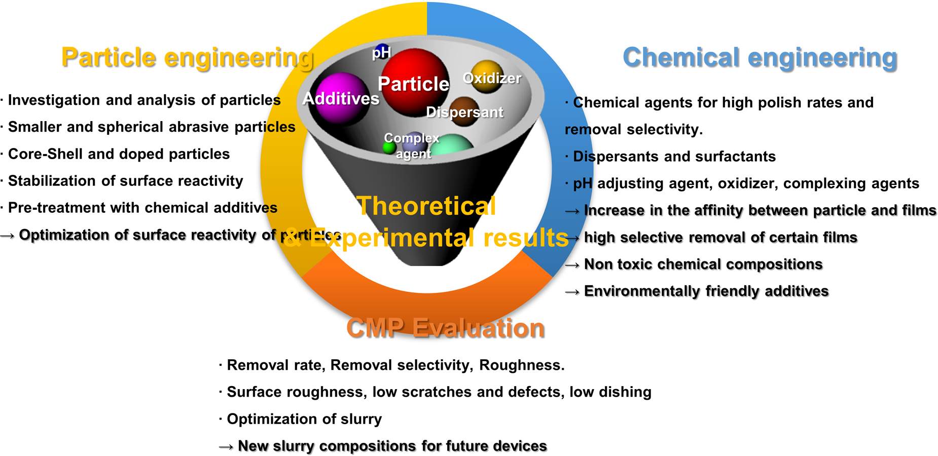
Figure 9: Schematic diagram of some research strategies for developing next-generation CMP slurries.
As stated earlier, the challenges and future research directions discussed here were related to CMP slurries and related to chemical and mechanical aspects of the CMP process. There has been significant progress in understanding the fundamental science and technology of CMP for the past several decades. Nevertheless, most of the models, methodologies, and techniques generally use laboratory-scale model systems under the assumptions about process parameters, which may or may not be relevant to explain high-volume-production fab-based CMP processes [Reference Roy148]. A close collaboration between academic and industrial R&D will help us to move forward with understanding the fundamental principles and technologies of the actual CMP process by minimizing the gaps between lab-based CMP models and fab-based CMP processes.
Acknowledgment
The author gratefully acknowledges Prof. S.V. Babu and Prof. D. Roy for many useful discussions, valuable comments, and suggestions.


 Open access