


The USA CRREL drill is a thermal coring device whose design was based on the information and experience obtained in CRREL’s development of deep core-drilling equipment. The first version of the drill was built in 1963 for the Canadian Department of Mines and Technical Surveys and was used by Dr W. S. B. Paterson to penetrate the ice cap on Meighen Island (lat. 80° N., long. 90° W.) in 1965. Dr Paterson’s performance report (Paterson, unpublished) suggested improvements which were incorporated in two more drills built in 1966 for the Australian National Antarctic Research Expedition and for the U.S. Antarctic Research Program. Other thermal coring drills have been developed independently; a select bibliography of papers concerning them can be found at the end of the paper. A description of the drill and its performance follows.
Equipment
The drill was designed for continuous coring in either temperate or polar ice or snow and was not designed to be used in fluid-filled holes. It is 4.6 m long and weighs 80 kg. An aluminum ring at the bottom of the cylindrical core barrel is heated by 18 cartridge heaters (see Fig. 1). The heated ring has an outside diameter of 16.2 cm and an inside diameter of 12.4 cm. It produces a hole 16.4 cm in diameter or larger and produces a core 12.2 cm in diameter or smaller, both diameters depending upon the drilling rate. Drilling rates vary with the temperature of the ice, from 2.3 m h−1 (1.50 inch min−1) at 0°C to 1.9 m h−1 (1.25 inch min−1) at −28°C with 3.5–4 kW of total power input.
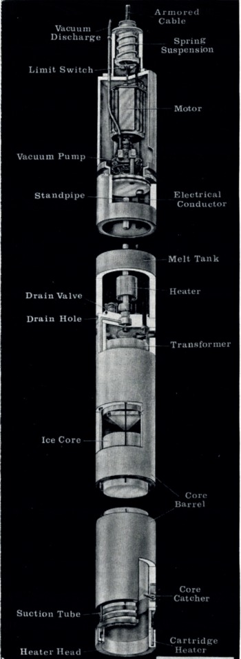
Fig. 1. Cut-away illustration of drill.
The melt water formed is pumped from the annular heater through heated nichrome tubes in the core barrel wall and into a laminated plastic cylindrical storage tank which is kept under a vacuum. The tank can hold the melt water from a 1.5 m coring run. A vacuum pump and motor are housed above the tank. Spring loaded core dogs at the bottom of the core barrel grip and retain the core. At the surface, the core is removed by manually retracting the core dogs. At the same time the melt water is also drained from the tank.
The other equipment consists of 450 m of cable, a generator, a hoist, and a tower (see Fig. 2). The cable is 1.2 cm in diameter. It contains two outer layers of steel armor which support the drill and enclose six power conductors. It is wound on an aluminum drum which has a brush and slip-ring assembly for transferring power from the generator. A modified “orthocyclic” winding principle provides perfect cable spooling without the use of a level winding device.

Fig. 2. Complete assembly.
A five-kilowatt gasoline generator provides electrical and mechanical power. Fuel consumption is about 3 l h−1. A control panel enables the operator to monitor voltage and current and actuate the heater or pump motor. Two limit switches on a spring suspension at the top of the drill actuate indicator lights on the control panel and permit the operator to keep the drill always in suspension, which is essential in maintaining a plumb hole.
A flexible shaft transmits power mechanically from the generator motor to the hoist. In the winch, the power is transmitted through a clutch and V-belt to a speed reducer and finally through a chain drive to the cable drum.
The 6.7-m tower consists of three sections of aluminum tubing, two of which are split and serve as shipping containers for the drill. The entire drive unit, cable drum, and tower assembly are mounted on a single aluminum frame. Depth is read on a counter which is mechanically operated through a flexible shaft extending the length of the tower and driven by the sheave at the top of the tower.
An operating cycle begins by manually braking the free falling drill to the bottom of the hole. The main heater and pump are turned on, and the drill advanced by manually controlling the cable payout with a hand wheel at the speed reducer input. After drilling 1.5 m, the hand wheel is reversed to break the core. The hoist then hauls the drill to the surface at an average rate of 18 m min−1
The total time needed to drill a hole of a given depth may be calculated from the formula

where t is the time, d the depth, L the length of core, h the hauling or lowering rate, m the drilling rate, and S the surface time between runs. Assuming d = 450m, L = 1.5m, h = 1 100 mh-1, m = 1.9 mh-1, and S = 0.25 h, the minimum time required for a 450 m hole would be 435 h. For a depth of 100 m, the minimum time would be 75 h.
All equipment is shipped in seven containers with a gross weight of 1180 kg. Assembly and operation of the equipment can be accomplished by two men.
Performance
A USA CRREL drill was used during the 1967–68 austral summer at “Byrd” station, Antarctica (lat. 80° 01′ S., long. 119° 31′ W.), to core-drill five holes from 57 to 335 m in depth. The following averaged data was obtained from the 335 m hole:
-
Penetration rate in firn: 2.4 m h−1,
-
Penetration rate in ice: 1.9 m h−1,
-
Ice temperature: −28.5°C,
-
Total power: 4 kW,
-
Actual power consumed by heater to melt ice: 2.9 kW,
-
Pressure on heater face: 2 100–3 500 kg m−1,
-
Fuel consumption: 31 h−1,
-
Core diameter: 12.2 cm,
-
Total time to complete hole: 260 h.
The time used to compute the drilling rates include a one to two minute pause near the bottom of each coring run. During this interval, the cable payout was stopped and a ring melted around the core to assist the dogs in gripping the core.
Core quality was good to a depth of 100 m. From 100 to 130 m, cores were shattered, probably a result of the sudden pressure release and the thermal shock. From 130 to 335 m, the cores remained whole but were extremely delicate to handle. Numerous fractures in planes approximately perpendicular to the core axis and spaced about 1 cm apart occurred over the length of the core. Near the bottom of the hole, the cores gained in strength but were still fractured. The hole remained plumb within a half diameter throughout its depth.


