The results of the advanced feasibility study are most promising from a qualitative viewpoint (i.e. the observed shift of the dynamic divide from the topographic divide, and measured trends in "steady-state" surface horizontal and vertical How rates, were predicted), and reasonable in a quantitative sense for the horizontal steady–state surface flow rates when appropriate flow laws were adopted. A section of the paper is devoted to a discussion of appropriate functional stress–strain-rate–emperature relationships for ice. However, a number of limitations—isothermal behaviour, simplified basal sliding mechanism (linear elements), approximate bed profile, assumed flow relationships, two-dimensional model, and small deformation theory—were involved at this stage.
As a first refinement of the simulation model, emphasis was placed on the influence of the bed profile. For the Barnes Ice Cap, bed profile influences are more significant than anticipated. While the computed divide shift of 200 m is perhaps fortuitously close to the measured shift of 150 m, given the approximations, it is clear that the finite-element simulation programme can be developed to give any necessary refinements. For instance, the thermal regime of the ice mass is being considered through a finite-element method transient heat-flow analysis using the heat flux (and frictional heat generation where appropriate) from the underlying rock, and glacier surface elevation–temperature data, as the basic inputs. Since step-by-step procedures have been adopted throughout, large deformations and the mass balance are also readily incorporated into the incremental, uncoupled, stress analysis. While a simple, idealized ice-cap problem is used to reduce computational time during the developmental stages, details on the application of the refined simulation to the Barnes Ice Cap and surging are given. The finite-element simulation techniques described should have other applications in ice dynamics.
Discussion
D. A. Yuen: What is the Poisson ratio used in your calculations? What is the criterion foryour time step?
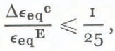
J. J. Emery: The Poisson ratio used for the solutions reported was 0.40. This value was selected from the literature as being representative for ice at low rates of loading. Any time interval ∆t selected for a creep interval must be small enough to ensure stability of the incremental initial-strain solution process. Stability was ensured by adopting limits developed by Greenbaum (unpublished):
R. Brepson: When you compute ∆t at each step, do you choose a unique flow relationship for each element?
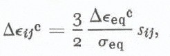
Emery: The components of creep-strain increment ∆εij c for each element and time step interval ∆tn are computed from: