


Introduction
Multipath effects in radar measurements can degrade the performance of direction of arrival (DOA) estimation by interference and can produce ghost targets in multipath directions that are mirror images of the real targets, and are thus difficult to eliminate [Reference Skolnik1]. If multipath reflections occur on a road, an interference pattern, dependent on the target's height, influences the received signal strength. The fading of interference minima can cause targets to disappear in certain distances [Reference Skolnik1,Reference Diewald, Klappstein, Sarholz, Dickmann and Dietmayer2]. Also, the signal phase is influenced by coherent multipath interference which complicates or even corrupts DOA estimation. If multipath reflections occur on a guardrail, the most probable effects are ghost targets or interference, depending on the specific scene, the vehicles' shape, and the radar's range resolution.
Polarimetric radars provide information about the parity of reflections such as even- and odd-bounce. Furthermore, they can be used to distinguish cross-polar from co-polar targets [Reference Cloude3]. In this paper, the DOA estimation is derived for the case of a uniform linear array (ULA) where it can be performed by a simple fast Fourier transform (FFT). Then, effects of polarimetric multipath propagations are discussed based on examples of multipath propagation over guardrails and roads. Finally, measurement results in an anechoic chamber demonstrate the parasitic interference effects of fading (which goes hand in hand with a corrupted DOA estimation) and ghost targets by multipath measurements of canonical objects. The change of polarimetric features in dependence of aspect angle is discussed. Also, measurements of the separability in angular direction between targets located in the same distance but with different polarimetric properties (as co- and cross-polar or even- and odd-bounce), are presented. At the end, a polarimetric filtering approach is introduced that allows polarimetric feature-selective DOA estimation.
DOA estimation for an 1D-ULA
The principle of DOA estimation for an 1D-ULA with N receiving elements is demonstrated by an off-broadside impinging plane wave at an angle φ in Fig. 1. The electric field of the received plane wave at the nth receiver (Rx) antenna element is described by:
 $$E_{rn} = E_{0r} e^{-j {\vec {k}} \cdot {\vec {r}}_n} = E_{0r} e^{-j\,({\vec {k}}_x + {\vec {k}}_y) \cdot nd {\vec {e}}_x},$$
 $$E_{rn} = E_{0r} e^{\,j\, {{2\pi} \over {\lambda}} \sin{(\varphi)} n d} \ ,n \in [0,N - 1], $$
where  ${\vec {r}}_n$ is the position vector of the nth antenna element, ${\vec {k}}$ is the wave vector, and λ the free space wavelength. The time dependence factor e jωt is neglected here. The Nyquist–Shannon theorem states that an azimuthal angle of arrival (AOA) φ can be reconstructed without error, if the plane wave is spatially sampled with the double spatial frequency [Reference Huang, Brennan, Patrick, Weller, Roberts and Hughes4]: ν s ≥ 2ν = 2/λ. Thus, the minimum distance of Rx antenna elements must be d ≤ 1/ν s = λ/2, which corresponds to a 180° phase shift. An array with this spacing between its elements is called λ/2 ULA. If the spacing becomes larger than λ/2, grating lobes emerge which cause ambiguities in the spatial spectrum [Reference Huang, Brennan, Patrick, Weller, Roberts and Hughes4]. In this paper, an 8-element λ/2 ULA is used for the DOA estimation. Thus, the spatial frequency can be simply estimated by a FFT processing and peak extraction. The estimated AOA from Eq. (2) is then: φ est = sin−1 (λν est).
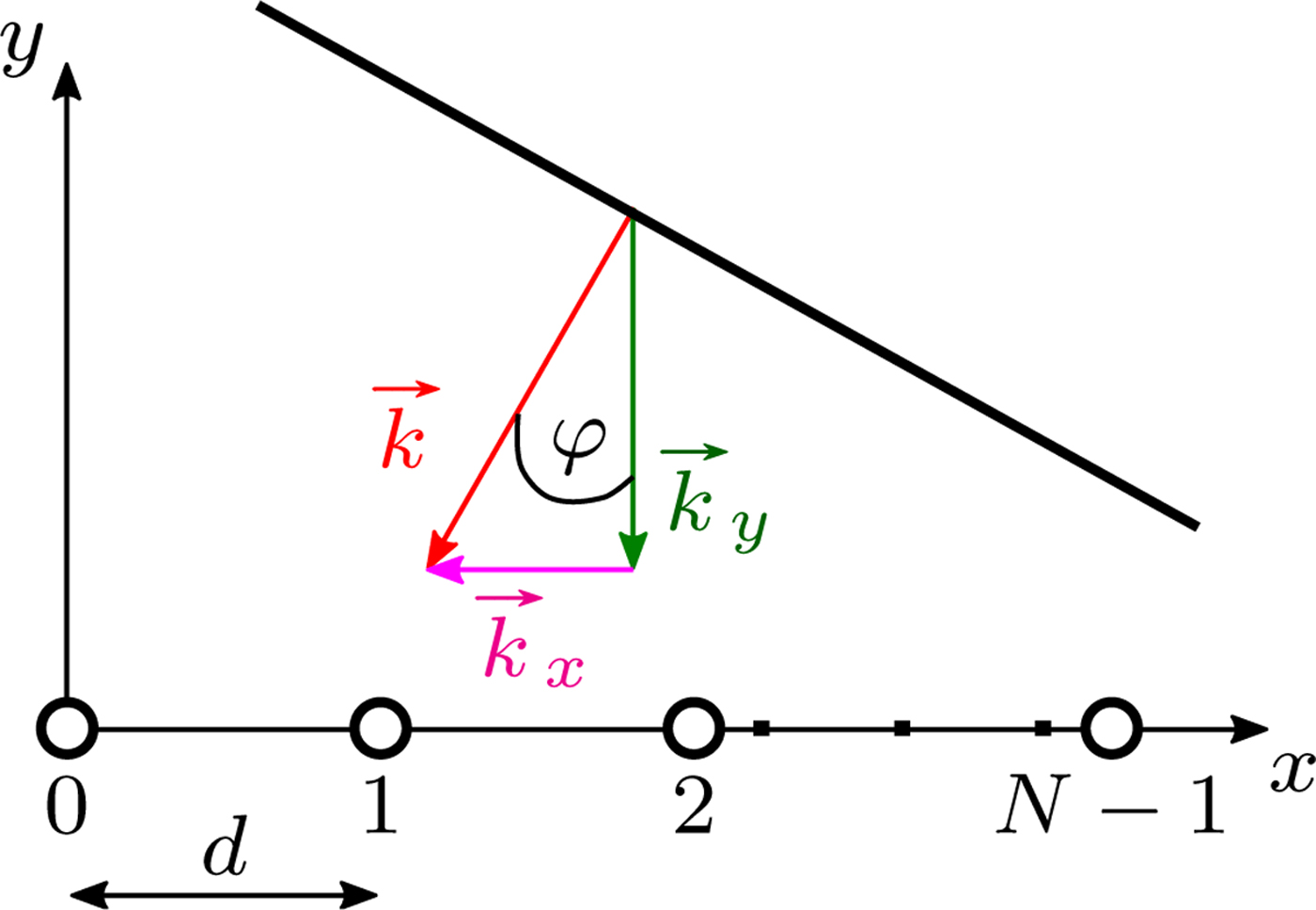
Fig. 1. 1D-ULA and off-broadside impinging plane wave.
Multipaths over roads and guardrails
In Fig. 2, multipath propagations over guardrails and over roads, which are important cases in automotive radar applications, are presented. Since automotive radars operate in the E-band and typical structures in traffic sceneries are very large compared with millimeter waves, wave propagation according to geometrical optics can be assumed.
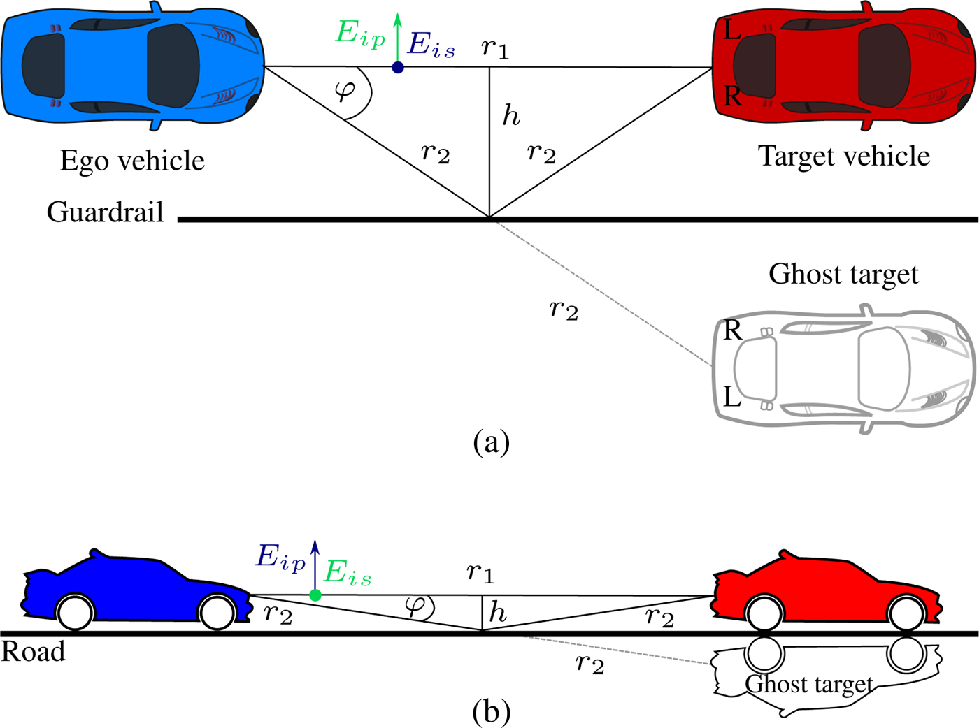
Fig. 2. Two important scenes of multipath propagation in automotive environments. (a): Guardrail case. (b): Road case.
Multipaths over guardrails
Considering Fig. 2(a), without loss of generality the vehicles and their scattering centers are located in the same distance h to the guardrail. Guardrails are metallic and the incidence can range from grazing to steep, depending on the distance h of ego and target vehicle to the guardrail. The main polarimetric effect occurring at guardrail reflections is that linear polarization is transformed to elliptical polarization upon reflection and vice versa. This change occurs due to a gradual phase shift between parallel (p)- and perpendicular (s)-polarizations to the guardrail (indicated by fields E is and E ip in Fig. 2(a)) over incidence angle. At a special incidence angle, called the principal angle, the phase shift between p- and s-polarizations becomes 90° and linear polarization is turned completely into circular polarization and vice versa. Attenuation effects are neglectable for the guardrail case due to the metallic material and its high conductivity [Reference Born and Wolf5]. Rough surface and diffuse scattering generally increase incoherent backscattering and thus act in a depolarizing way. This depolarizing effect can be described quantitatively by the scattering entropy [Reference Cloude3]. In this paper, rather smooth surfaces with a low scattering entropy are considered, so that a distinct classification in even- and odd-bounce is possible.
Three paths are important to analyze in case of Fig. 2(a). At first, the direct path d r1 = r 1 is considered. The information on this path contains the direct backscatter and correct DOA information about the target. The first multipath is d r12 = (r 1 + 2r 2)/2. This path has one bounce (reflection) more than the direct path and thus changes an odd-bounce scattering process into an even-bounce one and vice versa. This path only exists for a spherical target or a target with strong surface curvature and/or diffuse scattering. Otherwise, the radar signal is not scattered in a different direction than the backscatter direction and the path d r12 is thus non-existent. The second multipath d r2 = 2r 2 describes the propagation with two more reflections than the direct path and thus the bounce information of even- and odd-bounce is maintained. Furthermore, the target is seen in a different aspect angle than from the direct path which leads to deviating polarimetric scatter information.
Two cases of problems arise with multipath reflections:
• The indirect path length lies within or close to the range bin of the direct path. The resulting coherent constructive and destructive interference with the direct path leads to fading effects on the Rx channels. As a result, the DOA estimation performance is deteriorated and in the worst case, this leads to a wrong AOA estimation.
• The indirect path length lies in a different range bin as the direct path. The multipath reflection is detected as a ghost target with a ghost AOA φ. This ghost target is a mirror image of the real target and can only be revealed if the mirror effect is detectable or by additional information processing (e.g. that the target velocity is unreasonable at the detected position). In the guardrail case of Fig. 2(a) this is especially difficult, because of the bilateral (left/right) symmetry of most vehicles.
These problems, if present, can deteriorate the otherwise high performance of automotive radars.
Multipaths over roads
When the radar signal is reflected from a road's surface, the road can be modeled in the first approximation as a dielectric material. The reflection coefficients for dielectrics in the s- and p-polarized cases (indicated by E is and E ip in Fig. 2(b)) are described by the Fresnel equations. Ordinarily, the micro-roughness of asphalt is smaller or equal to one-quarter of the free-space wavelength λ (3.9 mm) at 77 GHz. Also, the statistical road unevenness leads to deviations from specular reflections. Therefore, modified Fresnel equations have to be used for reflections on roads [Reference Schneider, Didascalou and Wiesbeck6]. Furthermore, because of the roughness, the reflected wave is partly depolarized during the diffuse scattering process which increases the scattering entropy. Typically, radar sensors are not mounted on top of vehicles but rather close to the road. Thus, the incidence of over-the-road reflections is rather grazing. Then the direct path length d r1 is very close to the indirect path lengths d r12 and d r2. Combined with the limited range separability, the indirect paths lie most probably in the range bin of the direct path and lead to interference effects and fading. Due to the rather grazing angle, the amplitude and phase differences of s- and p-polarized reflections are just marginal. For example, the reflectivity differences between s- and p-polarizations of a typical realistic rough asphalt surface for a monostatic sensor mounted at 30 cm height and a point target at the same height in a close distance of 5 m amounts to only 4.5 dB [Reference Schneider, Didascalou and Wiesbeck6]. Thus, the superposed power of all paths received by the radar follows an interference pattern over the target's range that is mostly independent of the polarization state [Reference Diewald, Klappstein, Sarholz, Dickmann and Dietmayer2]. This gives rise to partly vanishing targets for single-polarized as well as fully polarimetric radars in certain target distances. An approach to tackle this issue would be to use a bistatic or quasi-monostatic radar with widely distributed antenna channels in order to make use of path differences between the receive channels. If these path differences become large enough, the fading will not occur on all channels equally. On the other hand, it is possible to estimate the height of objects on the basis of the interference pattern [Reference Diewald, Klappstein, Sarholz, Dickmann and Dietmayer2].
Evaluating the foregoing statements, multipath reflections over roads show minor polarimetric detection potential and are thus not further investigated in this paper.
Measurement parameters and results
In the following, exemplary measurement results are presented in order to demonstrate the stated polarimetric effects in Section “Multipaths over guardrails”. Measurements are taken in an anechoic chamber with a fully polarimetric 8 × 8 time-division multiplexing multiple-input, multiple-output (MIMO) frequency-modulated continuous-wave quasi-monostatic radar sensor operating at 77 GHz. For the DOA estimation, four 8 channel MIMO arrays, where the central 6 array elements have a spacing of λ/2 and the 2 elements at the very ends on the left and right have a spacing of λ, are used. The array elements are arranged in azimuthal direction as shown in Fig. 1, so that the AOA φ can be estimated as stated. Two of these quasi ULAs comprise virtually overlapping linearly horizontal–horizontal (HH) and vertical–vertical (VV) polarized elements and the other two ULAs contain overlapping HV and VH polarized elements. Using this approach, the polarimetric relative phase shifts between HH and VV and HV and VH can be obtained, regardless of the DOA. The sensor is calibrated with a MIMO-adapted version of the isolated antenna calibration technique from [Reference Sarabandi, Ulaby and Tassoudji7]. More details on the radar system, the calibration, and the polarimetric MIMO antenna can be found in [Reference Visentin, Hasch and Zwick8]. The DOA estimation is done by a FFT with a zero-padding factor of 100 and a Kaiser window with 25 dB side lobe suppression over the stated λ/2 ULA channels, where the gaps at the very ends are filled with zeros. The resulting horizontal cross-range resolution in terms of the 3 dB beamwidth of the DOA spectrum's main peak amounts to approximately 14°.
Subsequent to these basic signal processing steps, the complete polarimetric scattering matrix (S-matrix) is formed and then decomposed, in order to differentiate the data in terms of polarimetric information. Any given 2 × 2 S-matrix can be decomposed into a coherent sum of basis matrices, each weighted by coefficients. These matrices and their coefficients correspond to canonical scattering mechanisms. One of the most common coherent decompositions is the Pauli decomposition, its name originated from the Pauli matrices, which are well-known, e.g. from quantum mechanics. Coherency in the sense of decompositions means that one single S-matrix is considered for the characterization of each resolution cell of the radar without any further averaging between the cells. The Pauli matrices form a set of four complex unitary and Hermitian matrices and build a basis for the vector space of 2 × 2 Hermitian matrices. These matrices are given as [Reference Feynman, Leighton and Sands9]:
 $$\eqalign{& {\bi \sigma }_{\bf 0} = {\bf I} = \left( {\matrix{ 1 & 0 \cr 0 & 1 \cr } } \right),\,{\bi \sigma }_{\bf 1} = \left( {\matrix{ 0 & 1 \cr 1 & 0 \cr } } \right),\, \cr & {\bi \sigma }_{\bf 2} = \left( {\matrix{ 0 & { - j} \cr j & 0 \cr } } \right),\,{\bi \sigma }_{\bf 3} = \left( {\matrix{ 1 & 0 \cr 0 & { - 1} \cr } } \right).} $$
They are used as the basis for the polarimetric Pauli decomposition which is written as [Reference Lee and Pottier10]:
 $${\bi S} = \displaystyle{a \over {\sqrt 2 }}{\bi \sigma} _{\bf 0} + \displaystyle{b \over {\sqrt 2 }}{\bi \sigma} _{\bf 3} + \displaystyle{c \over {\sqrt 2 }}{\bi \sigma} _{\bf 1} + \displaystyle{d \over {\sqrt 2 }}{\bi \sigma} _{\bf 2}.$$
The complex coefficients a,b,c, and d can be calculated by simple coherent additions and subtractions of the S-matrix components:
 $$\eqalign{& a = \displaystyle{{S_{hh} + S_{vv}} \over {\sqrt 2 }},\,b = \displaystyle{{S_{hh} - S_{vv}} \over {\sqrt 2 }}, \cr & c = \displaystyle{{S_{hv} + S_{vh}} \over {\sqrt 2 }},\,d = j\displaystyle{{S_{hv} - S_{vh}} \over {\sqrt 2 }}.}$$
As a new approach, the DOA estimation is performed for each component of the Pauli decomposition, where  $\tilde a$ describes the odd-bounce scattering part of the DOA spectrum, $\tilde b$ even-bounce scattering, $\tilde c$ cross-polar scattering and $ \tilde {\!\!d}$ antisymmetric components of the S-matrix which can mainly be neglected for a quasi-monostatic radar as is used in this work [Reference Lee and Pottier10,Reference Marino11]. The squared magnitude of the Pauli components describes the corresponding part of radar cross section (RCS). An overview of the described signal processing chain is presented in Fig. 3.
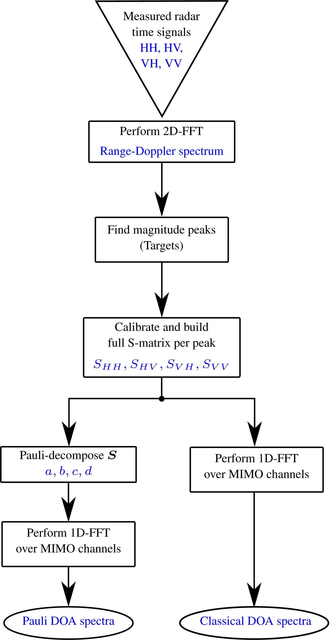
Fig. 3. Flow chart of the signal processing chain used in this paper.
Measurements of polarimetric multipath effects
The performed measurements emulate the guardrail case from Fig. 2(a). The corresponding setup is shown in Fig. 4. To model the guardrail case, the floor between target and radar is covered with metallic sheets. Also, the radar sensor is rotated by 90° so that the azimuthal direction is pointing towards the ground (the azimuthal antenna pattern has a broad 3 dB-beamwidth of 60° [Reference Visentin, Hasch and Zwick8]). The distances are chosen in such a way that all the three paths are separable - with a measurement bandwidth of B = 2 GHz the physical range bin size is 7.5 cm [Reference Huang, Brennan, Patrick, Weller, Roberts and Hughes4]. The lengths in the setup amount to d r1 = 5.2 m, h = 1.25 m, and d r2 = 2((r 1/2)2 + h 2)1/2 ≈ 5.8 m. Consequently, d r12 ≈ 5.5 m and φ = cos −1(r 1/2r 2) ≈ 25.7°. Different canonical objects are measured with these setup parameters.
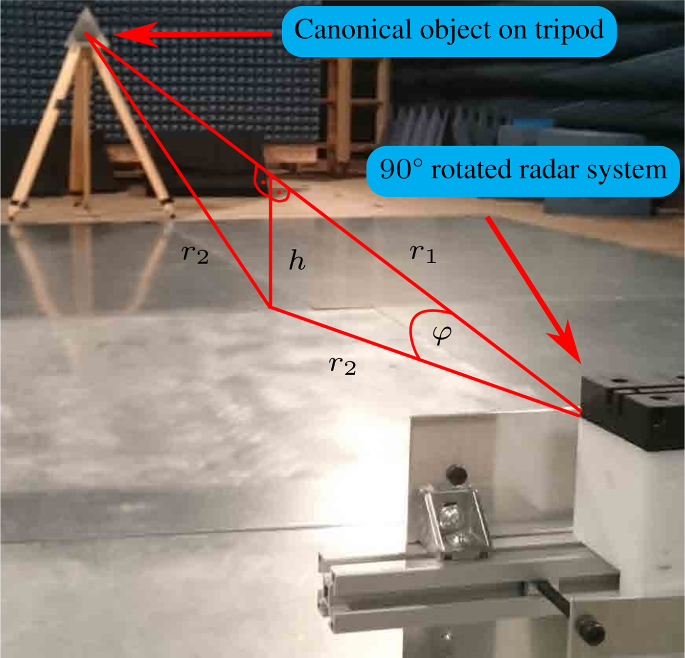
Fig. 4. Measurement setup in an anechoic chamber for modeling the guardrail case of Fig. 2(a) with rotated radar sensor and trihedral.
At first, a metallic sphere with radius r = 15 cm is installed as a target. The uncalibrated measured magnitudes are incoherently integrated over each of the four overlapping MIMO ULAs and the results are shown in Fig. 5. The three peaks of the different paths are clearly visible at d r1 ≈ 5.1 m, d r12 ≈ 5.4 m, and d r2 ≈ 5.7 m, respectively. In the special case of a sphere, radiation is backscattered in many different angles due to its curved surface. Subsequent to the path selection and calibration, the DOA estimation, as stated in the section “DOA estimation for an 1D-ULA”, is performed for each Pauli component. The estimation result for the direct path is given in Fig. 6(a). The AOA is estimated correctly for the  $\tilde a$ component, indicating that an odd-bounce target is detected close to 0° incidence. For the indirect paths d r12 and d r2, this is not the case. The corresponding results are shown in Figs. 6(b) and 6(c). As can be seen, the DOA cannot be estimated in the case of path d r12. From d r1 to d r12 the RCS of the $\tilde a$ component changes from −11 dBsm to −18.9 dBsm, whereas the RCS of the $\tilde b$ component changes from −26.5 dBsm to −7.4 dBsm, illustrating the change from odd-bounce to even-bounce due to the extra reflection on the metallic ground. Nevertheless, because of the coherent superposition of many paths similar to d r12, the DOA estimation is corrupted. Contrary to d r2, where only very few rays are reflected by the metallic floor at such an angle that they hit the sphere to be exactly bounced back, in case of d r12, many rays in different angles are bounced back by the sphere and are reflected by the metallic floor to hit the radar. Comparing Eq. (2), a superposed wave E sp of the direct path wave E dp and the indirect path wave E idp at the nth antenna for a λ/2 ULA can be formulated as:
 $$ \hskip -9pt E_{sp,n} = E_{dp,n} + E_{idp,n} = E_{0r}\left( {e^{\,jnk_1} + e^{\,jnk_2}} \right),$$
 $$E_{sp,n} = 2E_{0r}\,\cos \left( {\displaystyle{{n(k_1 - k_2)} \over 2}} \right). \exp \left(j {\displaystyle{{n(k_1 + k_2)} \over 2}} \right),$$
with k 1 = πsin (φdp) and k 2 = πsin (φidp). From Eq. (7) it is obvious that the interference modulates the received amplitude as well as the phase. In the measurements, this causes a RCS fluctuation of up to 15 dB over the co-polar MIMO channels and makes it impossible to estimate a reasonable DOA. This effect can be observed in Fig. 7, where the RCS values are plotted per virtual MIMO channel position and polarization combination. It is to be noted that the sphere is a pure co-polar target and thus the RCS values of the cross-polar combinations HV and VH are lower than the co-polar ones (HH and VV). The third multipath d r2 leads to the detection of a ghost target with a high odd-bounce component at an AOA of approximately 26°. The corresponding DOA estimation result is shown in Fig. 6(c).
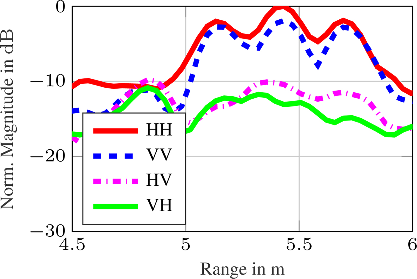
Fig. 5. Uncalibrated range spectrum of sphere target measurement for all S-matrix components (incoherently integrated over all MIMO channels).
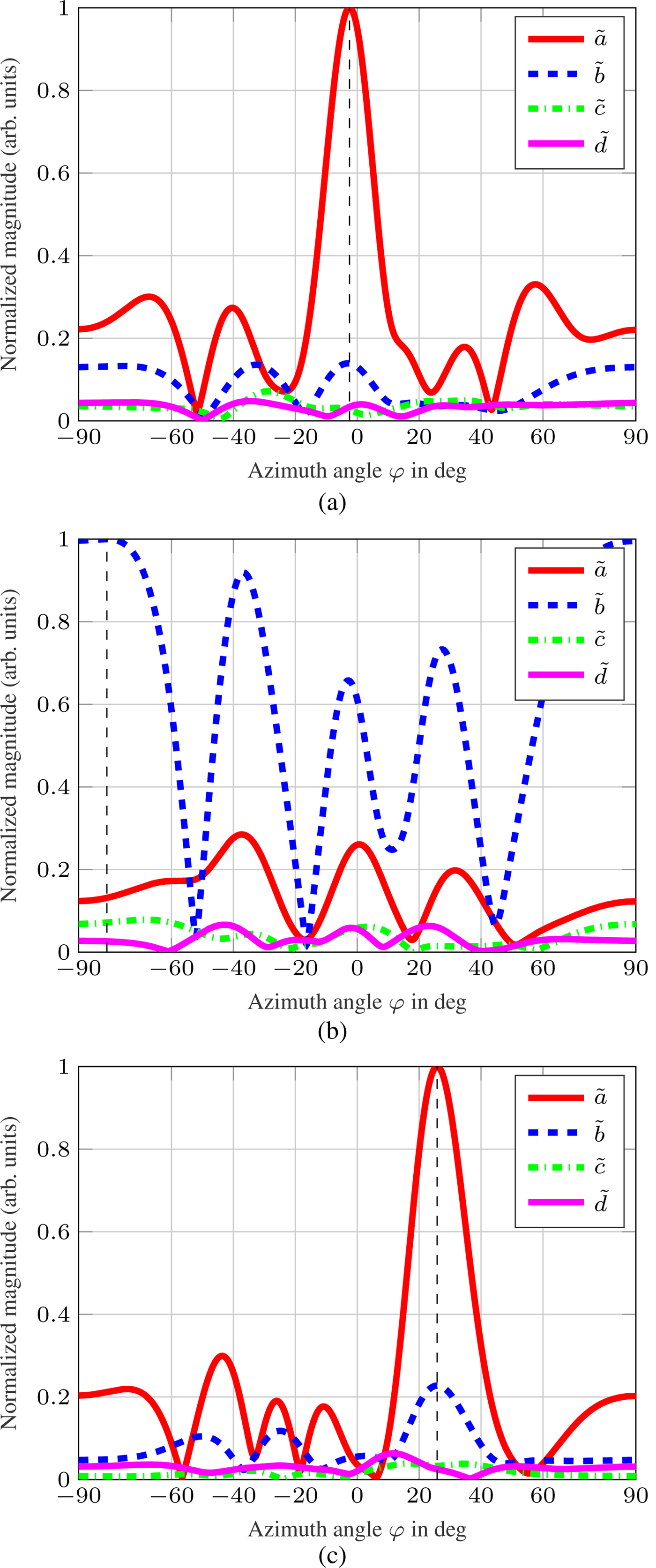
Fig. 6. Spatial spectra of Pauli components over azimuth angle of the measurement shown in Fig. 4 with a sphere instead of a trihedral. (a): Direct path. (b): Indirect path d r12. (c) Indirect path d r2.
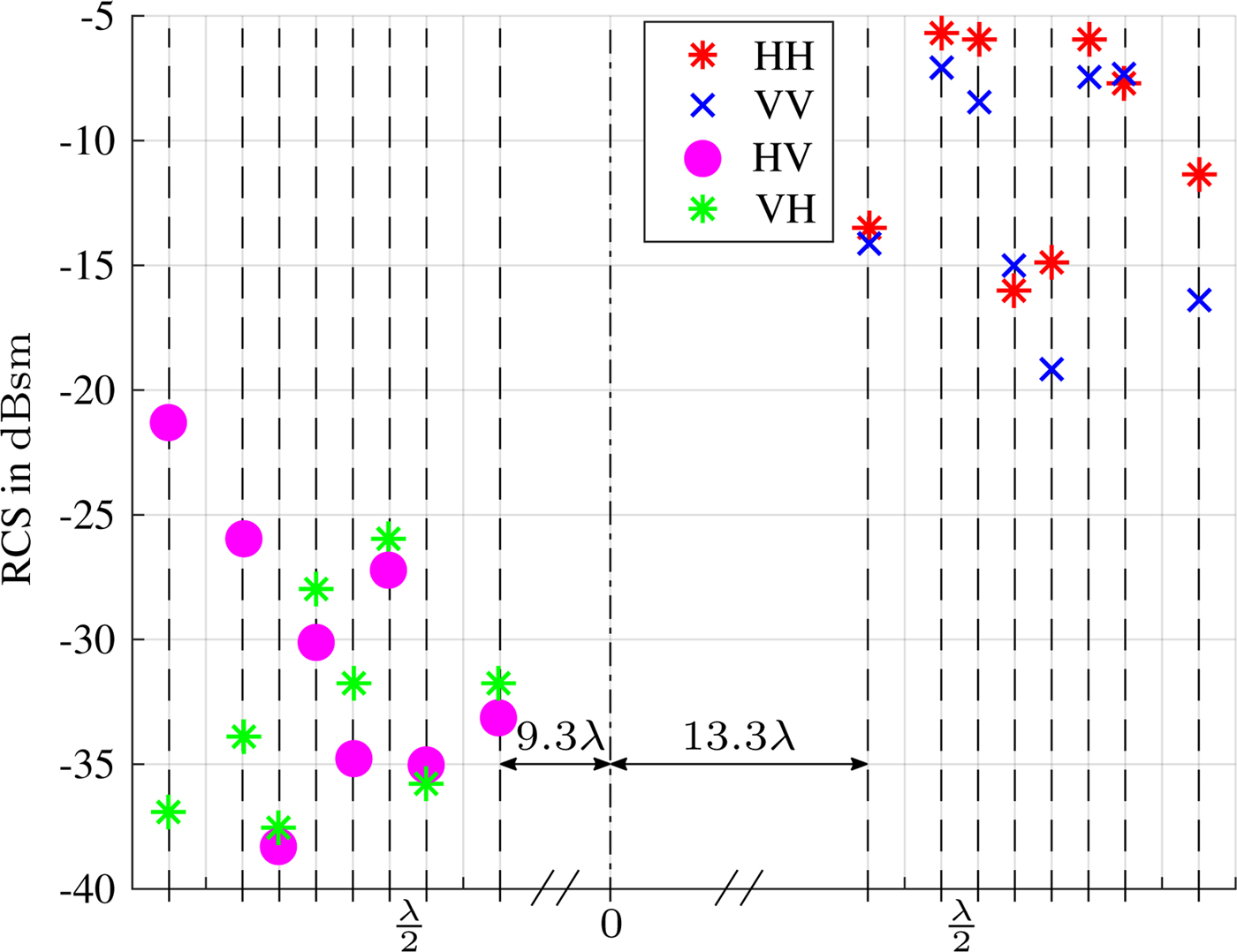
Fig. 7. Measured RCS of sphere, plotted on location of virtual MIMO channels over array element position for indirect path d r12. Dashed lines indicate the virtual array element locations and the distances between them are given in units of one wavelength on the abscissa.
Next, a trihedral corner reflector with 18 cm edge lengths as in Fig. 4 is installed. The evaluation of the direct path at 5.2 m results in dominant Pauli RCS components of  $\vert{\tilde a}{\vert}^2 \approx 18.8\,{\rm dBsm}$ and ${\vert} {\tilde b}{\vert}^2 \approx 1.3\,{\rm dBsm}$. The other components are neglectable. This clearly shows that the trihedral is classified correctly as a target with a high odd-bounce component and a 17.5 dB lower even-bounce component. The indirect path d r12 cannot be detected in the measurement. This is because the trihedral is mostly a backscatter object and does not scatter radiation to other directions [Reference Knott12]. However, the indirect path d r2 is detected at 5.8 m. The Pauli decomposition for this path results in the dominant parts ${\vert} {\tilde a} {\vert}^2 \approx 4\,{\rm dBsm}$ and ${\vert} {\tilde b} {\vert}^2 \approx 1\,{\rm dBsm}$. Also, the DOA estimation of $\tilde a$ and $\tilde b$ leads to φ ≈ 27° as expected. This shows that the multipath is detected as a ghost target at an AOA of 27° with an even-bounce RCS part that is only 3 dB weaker than the odd-bounce part. That is due to the high aspect angle, in which the trihedral is illuminated by the incoming rays. A trihedral seen in this aspect angle is not a pure trihedral anymore and exhibits a certain amount of dihedral scattering [Reference Knott12]. A part of scattered power comes from the upper two edges of the trihedral. This can be visualized, if the trihedral in Fig. 4 is observed from the direction of ray r 2.
The same aspect angle effect is observed when the trihedral is exchanged by a dihedral corner reflector with edge lenghts of 20 cm and its seam rotated by 0°. For the direct path, the dominant two Pauli RCSs are  ${\vert} {\tilde a} {\vert}^2 \approx 7.1\,{\rm dBsm}$ and ${\vert} {\tilde b} {\vert}^2 \approx 24.6\,{\rm dBsm}$ and for the indirect path d r2 (DOA also estimated at φ ≈ 27°) ${\vert} {\tilde a} {\vert}^2 \approx 7.9\,{\rm dBsm}$ and ${\vert} {\tilde b} {\vert}^2 \approx 19.6\,{\rm dBsm}$. This shows again, that the targets change if seen in a different aspect angle.
For a metallic plate with edge lengths of 28 cm, however, only the direct path is measurable, because of its very weak scattering in off-broadside directions [Reference Knott12].
Angular separability of different canonical objects
A validation of the polarimetric DOA estimation performance is presented in the following measurement. A trihedral and a dihedral (rotated once by 0° and another time by 45°) are arranged in the anechoic chamber in approximately the same radial distance to the radar, but in different off-broadside directions. A photo of the setup is given in Fig. 8. The uncalibrated magnitudes of the range spectrum are again incoherently integrated over each overlapping MIMO ULA and the results are shown in Fig. 9. The range spectrum peaks of the targets are overlapping at about 4.1 m and are thus not clearly separable. An evaluation of the Pauli component based DOA estimation for the overlapping range peaks is shown exemplary for the dihedral rotated by 45° case (which is a pure cross-polar target [Reference Visentin, Hasch and Zwick8]) in Fig. 10. As observed, the AOA of  $\tilde c$ shows an incidence angle of about −18°, whereas the AOA of $\tilde a$ shows an incidence angle of about 22°. The targets can be clearly identified by the corresponding Pauli components and the AOA is estimated correctly. The same holds, if the dihedral is rotated to 0° (which is a pure co-polar even-bounce target [Reference Visentin, Hasch and Zwick8]). Here, the AOA of the even-bounce $\tilde b$ component shows the dihedral at about −17° and the trihedral is still detected at about 22° of the odd-bounce $\tilde a$ component.
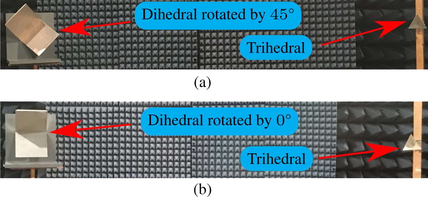
Fig. 8. Measurement setup of canonical targets separated only by angular position in anechoic chamber. (a): Dihedral as cross-polar target and trihedral as odd-bounce target. (b): Dihedral as even-bounce target and trihedral as odd-bounce target.
Fig. 9. Uncalibrated range spectrum of the measurement from Fig. 8(a) for all S-matrix components (incoherently integrated over all MIMO channels).

Fig. 10. Spatial spectrum of Pauli components over azimuth angle of the measurement from Fig. 8(a).
Polarimetric multipath filtering based on pauli parameters
So far, only measurements of objects positioned in boresight of the radar have been shown. In order to reveal the polarimetric multipath effects also in off-broadside scenarios, the trihedral from Fig. 8 has been placed in a position of approximately −25° at 5.2 m radial distance to the radar. A plot of the measured DOA spectrum is shown in Fig. 11(a). The AOA of the trihedral is correctly estimated at about −26°. As can be observed, the object only exhibits a co-polar DOA spectrum. Since already stated in the section “Measurements of polarimetric multipath effects”, the trihedral is an object that exhibits only pure backscatter, due to its faceted geometry. Thus, the indirect path d r12 is not detectable. It follows that only the indirect path d r2, which generates a ghost target, is found. Furthermore, the range resolution of the radar used in this paper is high enough (7.5 cm) to separate direct and indirect paths d r1 and d r2 due to the distance between them (60 cm with the measurement parameters stated in the section “Measurements of polarimetric multipath effects”). As a result, it is difficult to arrange a scenario in the rather small anechoic chamber in such a way that the different path lengths d r1 and d r2 come closer together so that they overlap in one range bin. However, a filtering ability can only be demonstrated if direct and indirect paths overlap or if they cannot be separated anymore. This would be the case for a radar with lower range resolution, so that for the measurement setup used in this paper direct and indirect paths overlap in one large range bin. For example, a radar with range resolution of 60 cm, respectively with a bandwidth of 250 MHz, could be used. Since the bandwidth of the radar used in this paper cannot be adjusted accordingly, a different approach must be used. Thus, the complex values of the peak from the indirect path measurement of the boresight positioned trihedral from Fig. 4 are extracted and superposed to the complex values of the peak from the direct path measurement results of the off-broadside trihedral. The superposition is done in the range spectrum and is placed on the same range bin as the peak of the detected direct path measurement. In other words, the indirect path of the measurement from Fig. 4, which is detected at a distance of 5.8 m, is superposed to the direct path of the measurement of the off-broadside trihedral, which is detected at a distance of 5.2 m. Additionally, to complicate the detection of the direct path at 5.2 m, the strength of the indirect path is amplified by a factor of six. Thus, the superposed spectrum comprises one time the direct path and six times the indirect path at the range bin of the direct path. This approach produces distinct fading over the MIMO channels. The resulting DOA spectrum is presented in Fig. 11(b). As can be seen, the peak of the indirect path is dominant over the one of the direct path in the DOA spectrum. If the highest peak would be considered as the AOA of the target, a significant error would be made. Also, the spectrum could be misinterpreted as a two-target scenario. By utilizing the Pauli parameters, it becomes possible to separate the spectral parts of the DOA spectrum concerning their different polarimetric features. In Fig. 11(c), the DOA spectra of all Pauli components are plotted over azimuth angle with several superpositions of them. These superpositions allow a selective filtering of polarimetric parts of the DOA spectra. For example, the spectrum of  $\tilde a - \tilde b$ allows a DOA estimation of the pure odd-bounce part with a negative superposition of any even-bounce part of the S-matrix of the considered target. Using this superposition, the correct AOA of the trihedral can be estimated at about −27°. This is based mostly on the aspect angle dependence effect which has been introduced in the section “Measurements of polarimetric multipath effects”. The trihedral seen from the indirect path d r2 exhibits a high even-bounce scattering part. Furthermore, the superposition of all parts $\tilde {\!a} + \tilde {b} + \tilde {\!c} + \tilde {\!\!d}$ of the DOA spectrum shows the combined DOA spectrum of the entire S-matrix of the detected target. It is used for normalization of the given graphs.
Fig. 11. Measured spatial spectra over azimuth angle of a trihedral placed at approximately −25° off-broadside and 5.2 m distance. (a): Direct path. (b): Superposition of 1× (a) and 6× indirect path d r2 from the measurement of Fig. 4. (c) Pauli parameters of (b) with a superposition and a difference of them.
In order to use the filtering advantageously, the correct difference of Pauli components has to be selected. For example, the difference of  $\tilde a - \tilde c$ in Fig. 11(c) would have almost no effect and would result in just the odd-bounce component $\tilde a$, because the cross-polar component $\tilde c$ is almost zero. One approach is to use a threshold value in the spectra on which a decision can be based if a difference is feasible or not. In this example, a threshold of 0.15 can be used. This would lead to the knowledge that parts $\tilde a$ and $\tilde b$ lie above the threshold value, whereas parts $\tilde c$ and $\tilde d$ remain below the threshold value. As a result, the difference of the $\tilde a$ and $\tilde b$ parts can be calculated and is promising to give new insights. However, it remains an open question if the detected polarimetric parts in the spectra originate from multipaths or from real objects in the same range bin, as in Fig. 10, if the measured scenario is unknown. Nevertheless, the approach enables the possibility to split the DOA spectrum in its polarimetric parts and make use of the filtered spectra. Detection of fading over the channels or other superior knowledge like taking into account the shape of the target or also detection of a close-by guardrail is needed to reveal the physical origin of the spectral parts.
Conclusion
In this paper, two important cases of multipath propagation over roads and guardrails in automotive radar scenes have been discussed. A new approach of polarimetric DOA estimation using coherent Pauli decomposition parameters, and measurement results of canonical objects on multipath reflections in an anechoic chamber have been presented. The measurements have demonstrated that targets change their polarimetric scattering behavior in dependency of aspect angle. Also, targets with different polarimetric properties as e.g. a pure cross-polar and co-polar target have been clearly separable in AOA, even if not separable in range. It has been shown that multipaths with an odd number of reflections turn a point target from even- to odd-bounce and vice versa, whereas multipaths with an even number of bounces do not change the parity of reflections. If multipath reflections fall into one single range bin, interference effects can lead to amplitude fading (which is detectable over the radar channels) and a corrupted DOA estimation. If not, a ghost target, which is a mirrored version of the original target, is detected in the direction of the multipath ray. These measured effects show polarimetric differences between direct path and multipaths and can be used to classify multipaths if the original target is known in advance and the polarization state change of the multipaths can be recognized. Otherwise, not only polarimetric information but also additional information (e.g. classification of a guardrail as such) is required. In the case a change of polarimetric features is detected, a filtering approach has been introduced which allows polarimetric feature-dependent DOA estimation correction. In future, machine learning and tracking algorithms could serve to recognize even small polarimetric feature changes of aspect angle over time and thus reduce the negative effects of interference and ghost targets, emerging from multipath reflections on guardrails, roads, road users or other objects.
 Tristan Visentin received his bachelor's and master's degrees in electrical engineering (B.S.E.E. and M.S.E.E.) from the technical university of Berlin, Germany in 2010 and 2014, respectively. He is currently pursuing his Ph.D. degree at Karlsruhe Institute of Technology (KIT), Germany. His funding is raised completely by the corporate research sector of the Robert Bosch GmbH in Stuttgart, Germany. Currently, his main research interests are polarimetric radars at millimeter-wave frequencies.
 Jürgen Hasch received the Dipl.-Ing. degree in 1996 and Dr.-Ing. degree in 2007 from the University of Stuttgart, Germany. He is a senior expert on RF technology at the corporate research of the Robert Bosch GmbH in Renningen, Germany, where he is responsible for several EU and German public funded projects and university cooperations. He is a senior member of IEEE, member of MTT TCC-27 and ITG-FA Mikrowellentechnik. He serves as a reviewer for several journals and conferences. His main interests are RF-based sensing technologies, integrated millimeter-wave sensors in the 60–240 GHz range, and on-chip antennas. He has authored more than 40 scientific papers and holds more than 15 patents.
 Thomas Zwick (S'95-M'00-SM'06) received the Dipl.-Ing. (M.S.E.E.) and the Dr.-Ing. (Ph.D.E.E.) degrees from the Universität Karlsruhe (TH), Karlsruhe, Germany in 1994 and 1999, respectively. From 1994 to 2001 he was Research Assistant at the Institut für Höchstfrequenztechnik und Elektronik (IHE), Universität Karlsruhe (TH), Germany. In February 2001, he joined IBM as a Research Staff Member at the IBM T. J. Watson Research Center, Yorktown Heights, NY. From October 2004 to September 2007, he was with Siemens AG, Lindau, Germany. During this period he managed the RF development team for automotive radars. In October 2007 he became appointed as Full Professor at the Karlsruhe Institute of Technology (KIT), Germany. He is Director of the Institut für Hochfrequenztechnik und Elektronik (IHE), KIT. His research topics include wave propagation, stochastic channel modeling, channel measurement techniques, material measurements, microwave techniques, millimeter wave antenna design, wireless communication, and radar system design.


