


1. Introduction
To resolve various drilling limitations and problems, such as logistical difficulties presented by heavy, power-hungry conventional drilling rigs, an advanced drilling system, i.e. the electromechanical cable-suspended drill, was developed in the 1940s. The main feature of this technology is the use of an armored cable with a winch instead of a pipe string to provide power to the downhole electric drive and retrieve the downhole assembly. In contrast to conventional rotary drilling, where the fluid is normally pumped to the bottom of the hole from the surface, an electromechanical drill suspended on a cable uses a bottom circulation system with a downhole pump and chip chamber for filtering the fluid and collecting the cuttings.
The first electromechanical cable-suspended drill – ‘Electrodrill’ – was invented and designed by A. Arutunoff (USA) in 1947 (Arutunoff, Reference Arutunoff1953). During initial tests, numerous wells were drilled in sedimentary rocks as deep as ~400 m. Because of the insufficient power and low drill-bit weight produced by Electrodrill, the penetration rates did not exceed 4.2 m h−1. Moreover, the friction antitorque system caused numerous accidents involving borehole wall collapses and drill sticking, resulting in the termination of these activities.
In the 1940s and 1950s, pipeless cable-suspended drilling technology was developed in the Soviet Union (Minin and others, Reference Minin, Pogarskyi and Chefranov1956). To equilibrate the counter-torque, the drill bit was alternately rotated in both directions at a certain prescribed rate, and the torque of the drill bit was balanced by the inertia of the electromechanical drill body. This project was also terminated, because the hole-making capability was low.
In 1964, Arutunoff's Electrodrill was purchased by the US Army Cold Regions Research and Engineering Laboratory (CRREL) and modified for glacial research (Ueda and Garfield, Reference Ueda and Garfield1968). This was a turning point in the development of ice-core drilling technology. Since the first CRREL drill was implemented, at least six different electromechanical drills for fluid-filled boreholes have been designed in the USA, Denmark, Russia, France, Germany, Switzerland and Japan for deep-ice drilling, e.g. ISTUK (Gundestrup and others, Reference Gundestrup, Johnsen and Reeh1984), KEMS (Kudryashov and others, Reference Kudryashov, Vasiliev and Talalay1994), PICO-5.2″ (Stanford, Reference Stanford1994), JARE (Takahashi and others, Reference Takahashi2002), Hans Tausen (Johnsen and others, Reference Johnsen2007) and DISC (Shturmakov and others, Reference Shturmakov, Lebar, Mason and Bentley2007). Some of these drills are illustrated in Figure 1. CRREL, ISTUK and PICO-5.2″ drills have been obsolete and are not in use anymore.
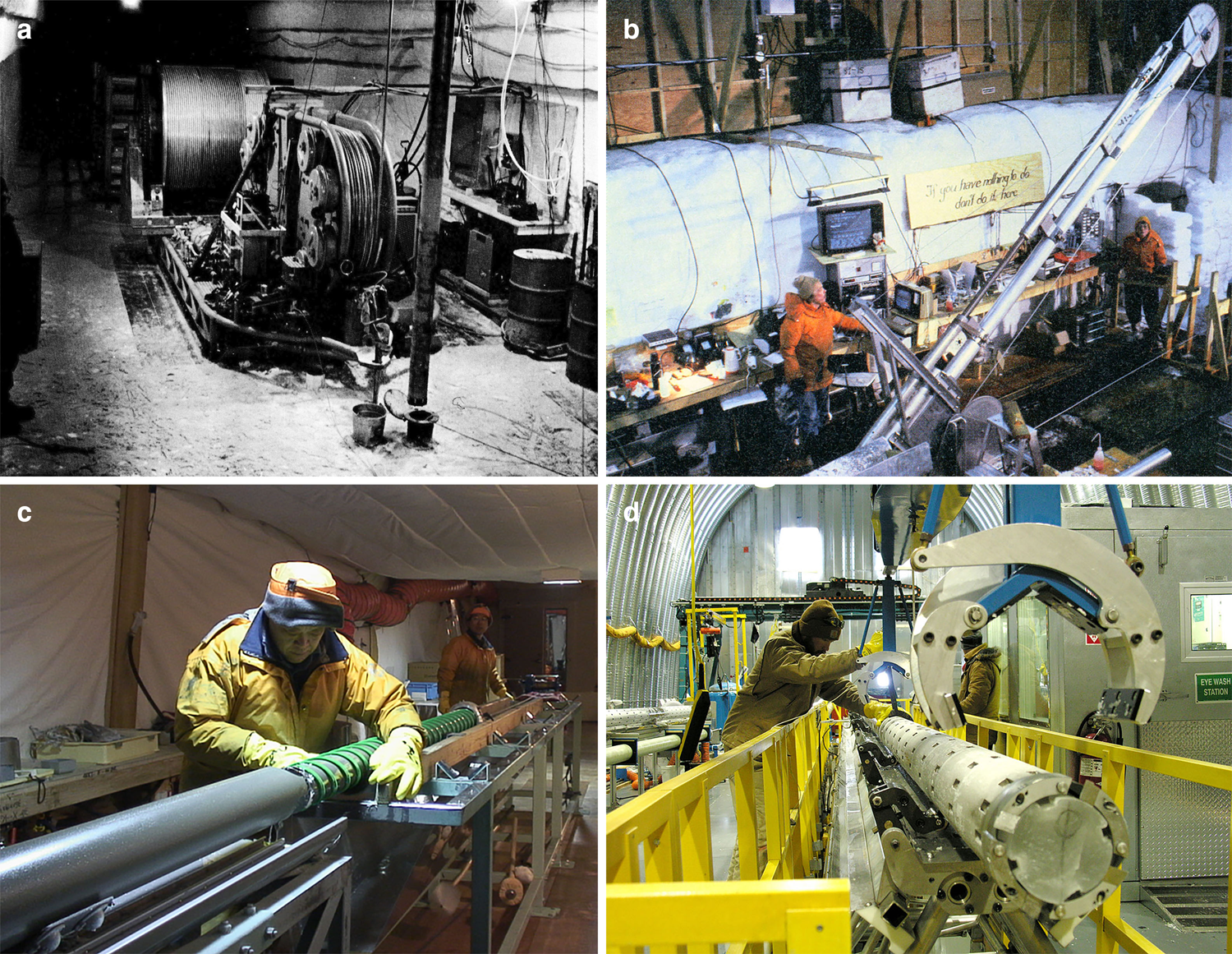
Fig. 1. Examples of electromechanical cable-suspended drills: (a) electrohydraulic hoist with 3650 m of cable and CRREL drill in the foreground, Byrd Station, West Antarctica, 1967–1968 season; (b) drilling operations with ISTUK drill at Dye-3, Greenland, 1981; (c) JARE drill in Dome F drilling trench, East Antarctica, season 2005–2006; (d) DISC drill servicing, WAIS Divide, West Antarctica, 2007–2008 season (all photos from Talalay, Reference Talalay2016).
Electromechanical cable-suspended drills have proven to be the most reliable drilling systems for ice-core drilling to depths exceeding 400–500 m. Recent intermediate and deep-ice drilling projects with cable-suspended drills have succeeded at various sites in Antarctica, the Greenland ice sheets and the Russian Arctic (Talalay, Reference Talalay2016). However, there are still engineering problems related to the designs of the drills, limiting their applicability. The CRREL drill is extremely heavy (1.2 tons), long (25 m) and power-consuming (13 kW) and requires a powerful capstan hoist and a large 32 m-tall tower. The piston pump of the ISTUK drill is very sensitive to cold environments, and ice-chip clogging often occurs in the narrow square channels outside the drill. KEMS and DISC drills have complicated drive systems with two motors and low-efficiency circulation systems. PICO-5.2″ is very heavy (730 kg) and long (27.5 m).
JARE and Hans Tausen drills have an auger inner barrel and a booster that cannot create discharge pressures and are not considered to be liquid pumps (Talalay, Reference Talalay2006). They apparently carry chips via a mechanical conveyor action that is generally not sufficient to remove all the chips produced at the bottom of the hole. Thus, a dual-action piston pump with a special design was installed instead of a booster in the improved Hans Tausen drill, but the pump has a relatively low volume efficiency (~0.7) and produces an uneven flow with a pulsation frequency of 4 Hz.
In their common design, the ISTUK, JARE and DISC drilling systems are unable to penetrate subglacial bedrock. However, CRREL, KEMS and PICO-5.2″ were modified for subglacial bedrock coring and made four successful penetrations in Greenland (Camp Century and GISP2), the Russian Arctic (Severnaya Zemlya archipelago) and Antarctica (Taylor Dome) (Talalay, Reference Talalay2013). Hans Tausen drill was also modified for subglacial coring but the bedrock interface at NEEM borehole (Greenland) was not reached because subglacial water refreezing into the newly formed borehole hindered further penetration (Popp and others, Reference Popp, Hansen, Sheldon, Schwander and Johnson2014). The main problems of subglacial drilling using a cable-suspended electromechanical drill are related to the insufficient near-bottom fluid flow, low axial loads and slipping of the antitorque system.
To drill through the East Antarctic Ice Sheet and recover bedrock samples, a new, modified version of the cable-suspended Ice and Bedrock Electromechanical Drill (IBED) was designed at the Polar Research Center of Jilin University (JLU) (Talalay and others, Reference Talalay, Siegert, Jamieson and White2017). The design efforts mainly focused on the reliability and unification of different drill components. Three related papers describe the general concept of the drilling rig (Talalay and others, Reference Talalay2021), auxiliaries (Fan and others, Reference Fan2021) and control system (Zhang and others, Reference Zhang2021).
2. IBED drilling system
The modules of the IBED can be changed for drilling in firn, ice, debris-containing ice and bedrock, which allows three different tasks to be accomplished: (1) auger drilling in the upper snow–firn layers with sequential reaming for casing installation, (2) coring in solid and debris-containing ice with near-bottom fluid circulation and (3) bedrock-core drilling (Fig. 2).
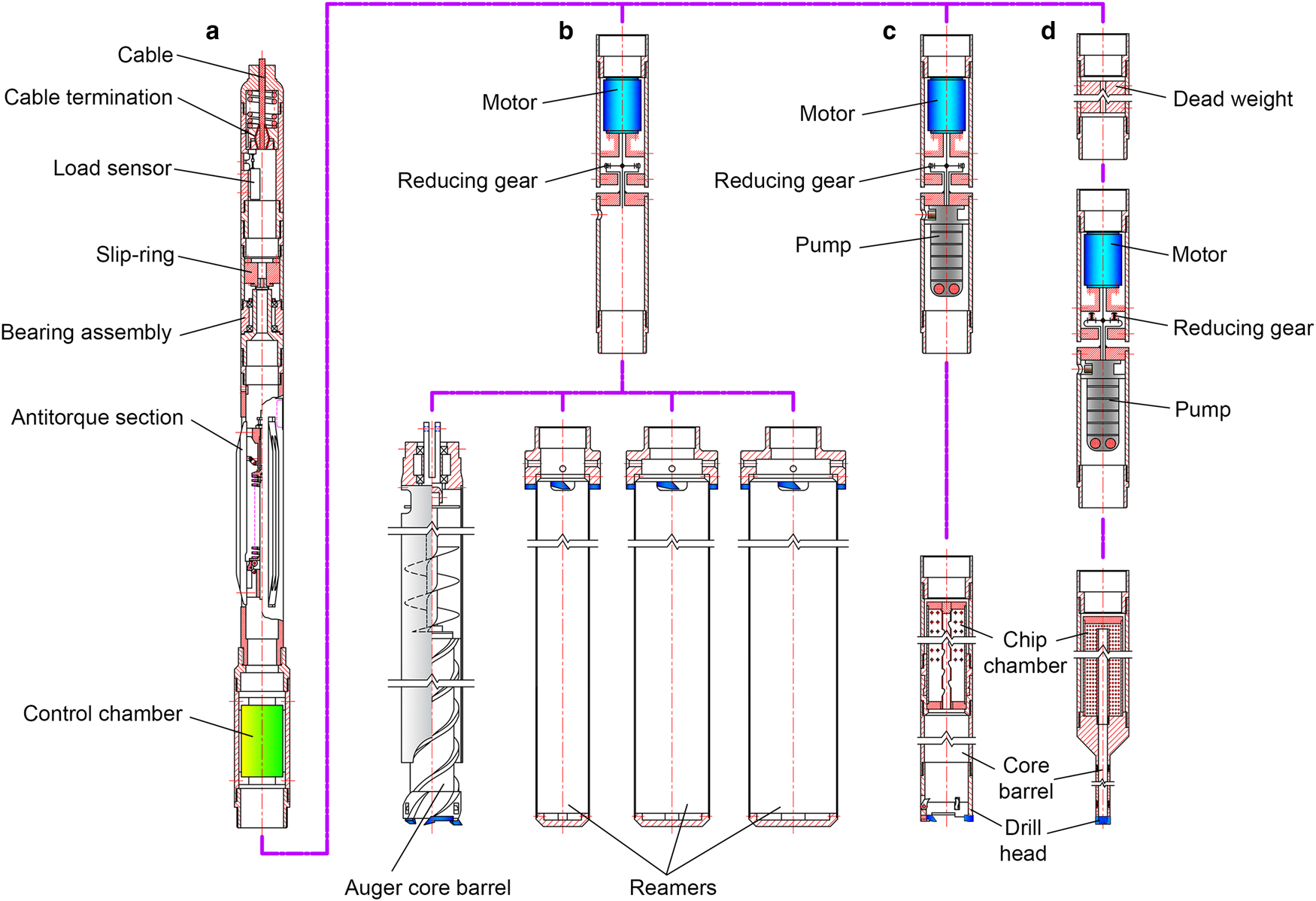
Fig. 2. Schematic of IBED drill: (a) upper invariable (except antitorque) section; (b) section for shallow drilling and reaming; (c) section for coring in solid and debris-containing ice with near-bottom fluid circulation; (d) bedrock-core drilling section.
The different sections of the drill are easily replaced, as all of them have the same threaded joint connections. The upper part is almost the same for all variants and includes four sections: cable termination, a slip-ring section, an antitorque system and an electronic pressure chamber. There are two types of antitorque systems: a leaf spring antitorque system for auger drilling and reaming in firn and an antitorque skate mechanism for ice and bedrock drilling (Talalay and others, Reference Talalay2014a).
The motor and gear sections have different rotation speeds according to the different modules. All modules contain a 3 kW AC3 × 380 V submersible motor of the Grundfos MS4000 type with a rated current of 7.7 A. The motor is pre-lubricated and can maintain an output pressure of up to 15 MPa. The gear reducer for drilling in snow–firn–ice decreases the drill-bit rotation speed to 90 rpm, and the gear reducer for subglacial drilling decreases the drill-bit rotation speed to 400 rpm. In modules for drilling with liquid, the shaft from the motor connects to the gear reducer for rotation of the core barrel and connects directly to the input shaft of the pump. This allows the installation of two different types of centrifugal pumps, depending on the drilling conditions: an SPK2-23/23 type with a nominal flow rate of 33.3 L min−1 and an outlet pressure of 0.65 MPa or an SPK4-11/11 type with a nominal flow rate of 66.7 L min−1 and an outlet pressure of 0.33 MPa. Both of these are vertical multistage immersible Grundfos SPK pumps with outer diameter (OD) of 100 mm, which are designed for pumping cooling lubricants for machine tools, condensate transfer and similar applications. The head of each type of pump is made of AISI 316 LN stainless steel and is suitable for use with aggressive corrosive media and media with high particle contents. The high efficiency of the pumps ensures a remarkably low heat input into the pumped liquid.
An auger is used to drill a pilot hole with a diameter of 136 mm to a depth ~10 m deeper than the firn–ice transition for installation of the casing. Then, the original borehole is reamed three times to diameters of 188, 228 and 258 mm. The ice chips are stored in a chip chamber with the same diameter as the previous borehole to prevent chips from dropping into the borehole.
The lower part of the IBED for ice drilling with fluid circulation comprises two parts: a chip chamber to filter the drilling fluid and collect chips, and a core barrel with a drill bit. The chip chamber features a Johnson-type cylindrical screen, which is manufactured from a trapezoidal section of spiral-wrapped wire on loading rods with slots of 0.2 mm. The inner diameter (ID)/OD of the ice-core drill head is 105/136 mm. The length of the core barrel is 2.4 m. The lower part of the bedrock variant is adapted for coring hard rocks using a toothed diamond bit and contains a 1 or 2 m-long conventional single-core or double-core barrel, a chip chamber for gravity separation of rock cuttings and adjustable deadweights (200 kg at maximum) to increase the load on the diamond drill bit. The ID/OD of the diamond bit is 41/60 mm for the single-core barrel.
3. Laboratory testing methods
Two testing stands were constructed to test the IBED in the laboratory of the Polar Research Center, JLU, Changchun, North East China.
3.1. Outdoor testing stand
The first testing stand (Figs 3a and b) was located outdoors and operated during winter for ice-drilling tests when the ambient temperature decreased to the range from −15 to −20°C and at other times for rock-drilling tests (Talalay and others, Reference Talalay, Siegert, Jamieson and White2017; Hu and others, Reference Hu2019). Low air temperatures at the site can last for 2–3 months during winter and create good conditions for simulating the polar climate and ice drilling. The testing stand had a 10 m-tall mast, allowing experiments involving the short version of the IBED to be performed. The lengths of the core barrel and chip chamber in the short drill were 1.0 and 1.6 m, respectively, rather than 2.4 and 4.6 m, respectively, for the field version. The drill was hoisted by a 10 mm-diameter steel rope winch using a 7.5 kW AC motor and a 40:1 worm-gear reducer that served as a break.

Fig. 3. IBED testing facilities: (a) outdoor testing stand (shortened version of IBED was placed inside piping simulating borehole); (b) outdoor testing site at the Polar Research Center, JLU, Changchun; (c) general structure of the ice-drill testing facility with a 12.5 m-deep ice well; (d) view inside the tall hall of the ice-drill testing facility with square steel piping simulating the borehole.
The borehole was imitated by a steel tubing with an ID/OD of 136/144 mm, making the clearance between the drill and the wall 4.5 mm on each side. The antitorque system was replaced by two pins inserted into the slots of a vertical tube to simulate a borehole. A 1 m-high cylindrical box with frozen artificial ice or a square box with a rock sample was joined by flanges to the lower end of the steel tubing.
3.2. Testing facility with ice well
The actual-sized IBED was tested at an ice-drill testing facility that can simulate drilling conditions as close as possible to the natural environment throughout the year (Figs 3c and d). The facility had a 15.2 m high chilled hall and an underground ice well (inside the steel liner) with a size of Ø 1 m × 12.5 m (Wang and others, Reference Wang2018). The ice temperature could be maintained as low as −30°C. A rotary drilling platform on the second level of the tall hall allowed for the drilling of at least nine holes with a diameter of <150 mm around the perimeter of the ice well without requiring refreezing.
The square steel piping with an inner width of 135 mm was installed on top of the ice well and simulated the borehole. The sections of the square steel piping were tightly bolted together; the height was adjusted according to the lengths of the different IBED versions. To start the drilling test, the field antitorque system was replaced by a bar with a square cross-section, which freely passed through the steel piping. When the antitorque system could enter the ice well, the square steel piping was removed for convenience. Four drilling parameters – the drilling load, rate of penetration (ROP), drilling depth and motor current – were displayed in real time on the screen and stored in a personal computer database.
3.3. Tested drilling fluids
For drilling in ice to depths of >300–400 m, it is necessary to use fluid to prevent borehole closure and remove chips from the drill head (Talalay and others, Reference Talalay2014b). Thus, three types of drilling fluids were compared in the ice-/bedrock-drilling tests: aviation fuel Jet A-1, hydrocarbon solvent Exxsol D60 and silicone oil KF96–2,0cs.
Jet A-1 is a straw-colored and transparent liquid with a pungent smell. Under normal conditions, it has a density of ~800 kg m−3 and a viscosity of ~1.5 mm2 s−1 (Talalay and Gundestrup, Reference Talalay and Gundestrup2002). The density and viscosity of Exxsol D60 are similar to those of Jet A-1; however, the content of aromatics (the most dangerous hydrocarbons for human health) in turbine fuels is 20–22%, and that in Exxsol D60 is typically <1%. Thus, the use of the solvents is preferable. Jet A-1 and Exxsol D60 have a density slightly lower than that of ice. Therefore, they cannot fully compensate for the overburden pressure of ice but can be used for intermediate drilling in cold ice where the borehole closure is slower than that in deep holes.
Silicone oil of the KF96–2,0cs type is a low-molecular-weight dimethyl siloxane oil (DSO). It is a clear, colorless, odorless, hydrophobic and essentially inert liquid that is stable in contact with water, air, oxygen, metals, wood, paper and plastics (Talalay, Reference Talalay2007). The density of KF96–2,0cs (870–875 kg m−3 at room temperature) is suitable for the compensation of the ice-overburden pressure, and the viscosity (2.07 mm2 s−1) is suitable for the output of pumps and for drill lowering/hoisting operations.
Low-molecular DSOs are among the most promising types of drilling fluids. This is why they were selected as the circulating medium for the SUBGLACIOR probe (Triest and Alemany, Reference Triest and Alemany2014) and the RADIX rapid-access drilling system (Schwander and others, Reference Schwander, Marending, Stocker and Fischer2014). Thus far, DSOs have never been used in ice-core drilling projects. Therefore, their suitability for ice drilling was tested in laboratory experiments.
4. Ice-drilling tests
A total of 28 ice-drill testing runs were conducted to test the efficiency of the IBED with different drilling fluids, pumps and cutters (Supplementary Table S1). The first 24 runs were performed at the outdoor testing stand with the short version of the IBED (Fig. 4). Ice samples were frozen in cylindrical boxes at a temperature in the range from −15 to −20°C. All runs were completed after penetration of ~800 mm.
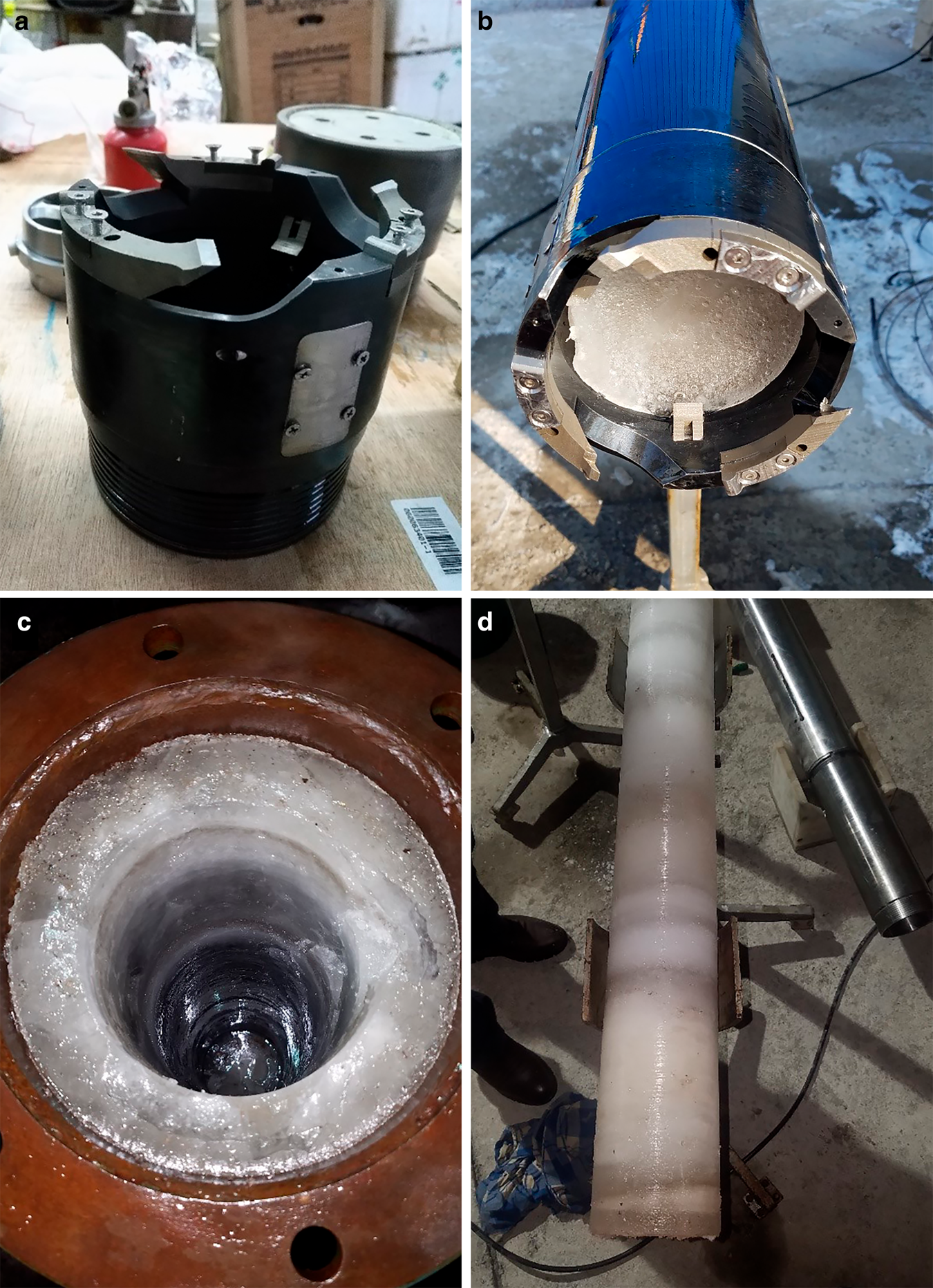
Fig. 4. Ice-drilling tests of the shortened version of the IBED at the outdoor testing stand: (a) ice-drill head; (b) core barrel with the ice core; (c) borehole drilled in an ice sample; (d) recovered ice core.
The maximum ROP was 12.9 m h−1, and the average ROP was 8.7 m h−1. The cutting load was maintained in the range of 400–800 N, at which the current was stable in the range of 4.5–4.7 A. The average density of the chips in the chip chamber was 350 kg m−3. In eight of the 24 runs, silicone oil was employed as the drilling fluid, and in the other runs, Jet A-1 was employed. The drilling performance appeared to be better with the silicone oil, likely because it lubricated the chip surface and prevented the chips from sticking together. The average ROP for the runs with silicone oil was 8.3 m h−1, and that for the runs with Jet A-1 was only 5.9 m h−1.
Three types of cutters – straight blades, skewed blades and staggered cutters – were tested (Fig. 5). The results indicated that the drilling performance with the staggered cutters was more stable than that with the other types of cutters, and the ROP was higher. Both tested pumps (SPK4-11/11 and SPK2-23/23) exhibited similar results; however, the ice chips appeared to circulate more smoothly with the SPK4-11/11 pump, possibly owing to the higher flow rate.
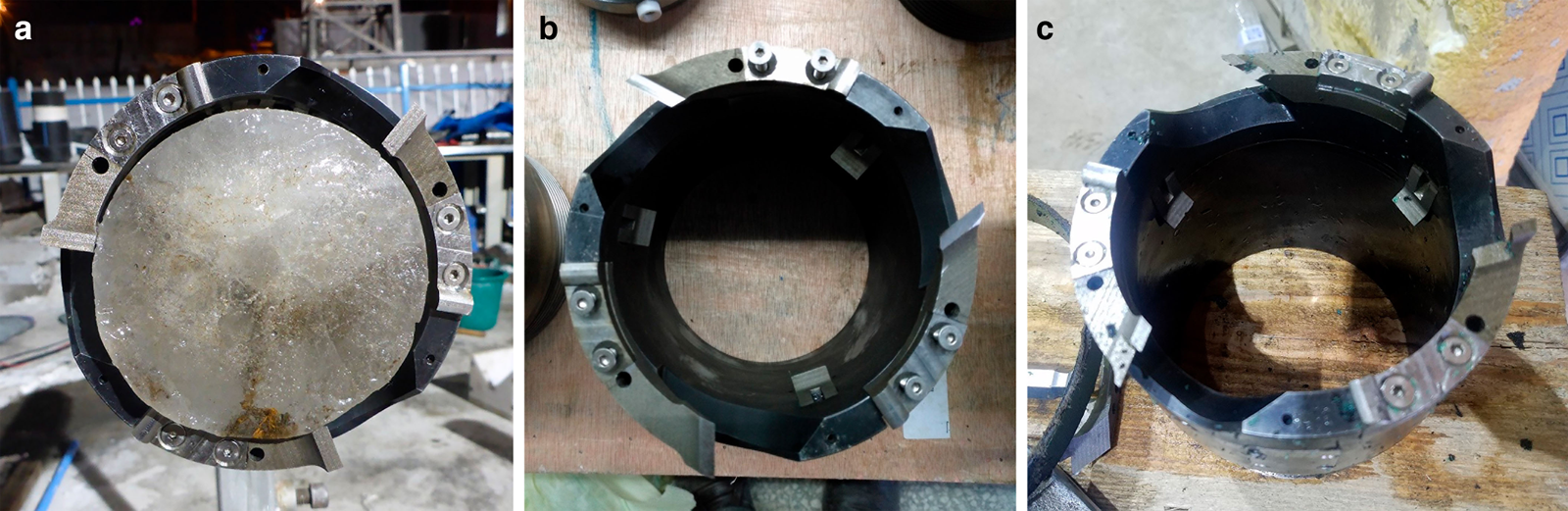
Fig. 5. Three types of cutters used in the IBED ice-drilling tests: (a) straight-blade cutters; (b) skewed-blade cutters; (c) staggered cutters.
Another four ice-drill testing runs were performed in the well with ice frozen at −20°C. Exxsol D60 was used as the drilling fluid. All the runs were completed after penetration of ~2.2 m (Fig. 6). The cutting load was higher than that in previous tests (~800 kN) at the same current (~4.5 A). The average density of the chips in the chip chamber was 333 kg m−3, and the maximum ROP was 8.75 m h−1.

Fig. 6. Tests of the full-scale version of the IBED in an ice well: (a) core barrel with the recovered ice core; (b) chip chambers; (c) ice hole after coring.
5. Drilling tests in debris-containing ice
Drilling operations in debris-containing ice with alternating hard and soft layers commonly experience both a low drilling efficiency and a high risk of complications (Yang and others, Reference Yang2017). To test the efficiency of the IBED with different drill bits in debris-containing ice, eight testing runs were conducted. Two types of debris-containing ice were prepared, with layers containing 10 or 30% granite particles (by volume) and particle sizes of 5–10 mm. Each sample comprised individual layers ~20 mm thick that were frozen layer-by-layer at a temperature range from −15 to −25°C in a cylindrical box with an ID of 205 mm.
The IBED version for drilling in debris-containing ice has the same design as the shortened version for ice drilling, except for the drill bit. Three custom-made PDC drill bits had the same ID/OD of 104/136 mm but different rake angles of the cutters (0° and −10°) and shapes of the cutting plate (flat or waved) (Fig. 7). The clearance angle of all cutters was 10°. Each drill bit had six round PDC cutters with a diameter of 16 mm.

Fig. 7. PDC drill bits with different cutters: (a) flat cutters with a rake angle of 0°; (b) flat cutters with a rake angle of −10°; (c) waved cutters with a rake angle of −10°.
In all tests, we used Jet A-1 as the drilling fluid. The maximum core length was 692 mm (Fig. 8). The maximum ROP (10.9 m h−1) was similar to that in ice, while the cutting load was slightly higher: in the range of 1000–1100 N (Supplementary Table S2). The penetration of the drill bit with cutters having a negative rake angle (−10°) was more stable than the penetration of the drill bit equipped with vertical cutters (rake angle of 0°). When the drill was equipped with the bit having waved cutters, it became stuck after penetration of 118 mm (the average ROP was only 1.57 m h−1). During subsequent cleanup, it was found that the chips from this run were significantly larger than those from the other runs; the chips blocked the filter screen and affected the fluid circulation.

Fig. 8. Tests of the shortened version of the IBED at the outdoor testing stand in debris-containing ice: (a) core with ice/rock mixture layers; (b, c) recovery of chips from the chip chamber; (d) borehole drilled in the sample.
6. Bedrock-drilling tests
A total of 48 bedrock-drilling testing runs were conducted to evaluate the efficiency with different drilling fluids (Jet A-1 or silicone oil), pumps, core barrels (single or double) and drill bits. The bedrock sample was a block of granite with a density of 2790–3070 kg m−3 and a shore hardness of >HS 70. The block had a cuboid shape, with a size of 100 × 100 × 800 mm. Before the test, the block was tightly fixed inside a square steel box.
The IBED drive unit was replaced by a unit with a higher rotation speed at the output shaft (400 rpm instead of the value of 90 rpm for ice drilling), and the ice-chip chamber was replaced with a chamber for gravity separation of the rock cuttings. Two types of core barrels were tested. During initial tests, a 1 m-long conventional single-tube core barrel was used. To improve the core quality, a double-tube core barrel was also designed. The outer tube of the double-tube core barrel rotated together with the chip chamber and drill bit, while the inner tube did not rotate, reducing the damage to the core caused by friction and vibration.
A conventional toothed impregnated drill bit with ten parabolic twin teeth and extensive waterways in between, was used for testing (Cao and others, Reference Cao2014). Because of the structural difference between the two types of core barrels, the drill bits had different IDs. The IDs of the drill bits for the single- and double-tube core barrels were 41 and 34 mm, respectively. To examine the influence of the clearance between the borehole wall and the drill body on the circulation of the drilling fluid, drill bits with different ODs (60, 61 and 62 mm) were constructed and tested. The matrix hardness of all the drill bits was 18HRC, and the diamond concentration was 4.4 ct cm−3.
During the drilling with Jet A-1, both the single- and double-tube core barrels were efficient enough to penetrate and retrieve a core of good quality (Fig. 9). Additionally, the ROP was in the range of 0.7–1.1 m h−1 at a low load (<2 kN) and torque (<30 Nm) (Supplementary Table S3). The hole was very clean, and all rock cuttings were collected in the chip chamber. The current of the driven motor was near 6.0 A at the beginning of the run; after the hole was opened, the current increased to 7.5 A and remained stable.
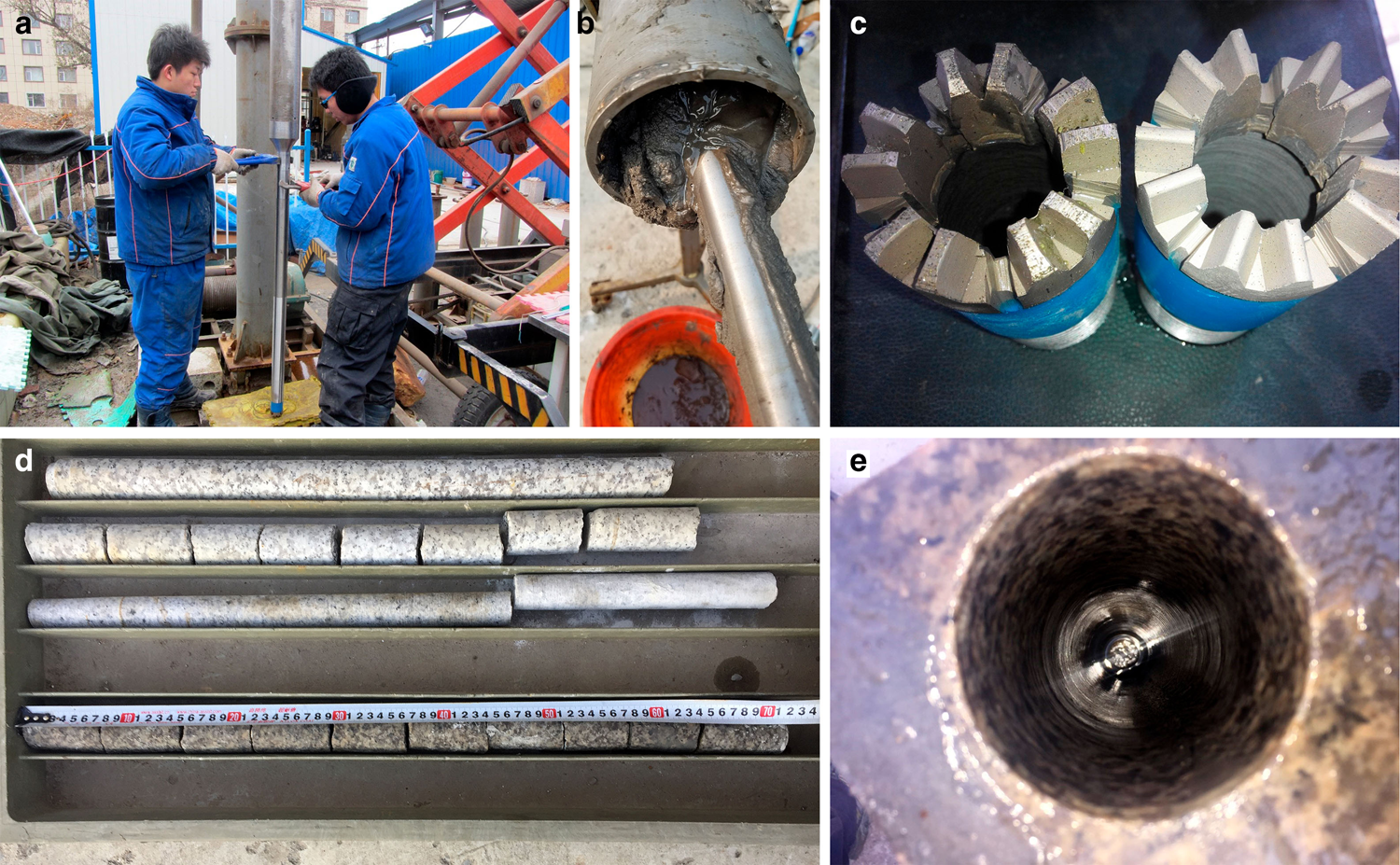
Fig. 9. Tests of the IBED on granite blocks at the outdoor testing stand: (a) assembling the drill; (b) bedrock chips; (c) worked-out and new toothed impregnated drill bits; (d) recovered bedrock core; (e) bedrock borehole.
In contrast to the drilling tests in ice, the drilling fluid significantly influenced the drilling performance in granite. In all 16 testing runs with silicone oil, the core barrel (both single- and double-tube) became stuck after penetration of 0.1–0.4 m, whereas the core barrel did not become stuck when Jet A-1 was used as the drilling fluid. The rates of penetration (0.2–0.65 m h−1) with silicone oil were also lower than those with Jet A-1. Additionally, the drill bits with large ODs (61 and 62 mm) were employed with both the single- and double-tube core barrels to determine whether the clearance between the borehole wall and the drill body affected the drilling-fluid circulation. However, the test results were mixed, and the reason why the core barrel became stuck was unclear.
7. Field testing
In December 2018–January 2019, drilling facilities were assembled at the ice-sheet edge near Zhongshan Station, East Antarctica, and preliminary testing was conducted. Then, a movable drilling shelter, movable workshop, living van and a sled with a fuel tank were transported to the test site, which was ~12 km south of Zhongshan Station on the flank of the Dålk Glacier, draining into the southeast part of Prydz Bay between the Larsemann Hills and Steinnes (Fig. 10). The site (69°28.18′S 076°20.79′E; 306 m a.s.l.) was in an area where the subglacial topography is tracked to the highest point. The presence of a subglacial hill in this area was first revealed by a Russian radar survey in 1991 (personal communication from S. Popov, 2018). The top of the subglacial hill was ~100 m a.s.l., ensuring dry, frozen-bed conditions for avoiding contamination of the subglacial hydrologic environment by drilling fluid.
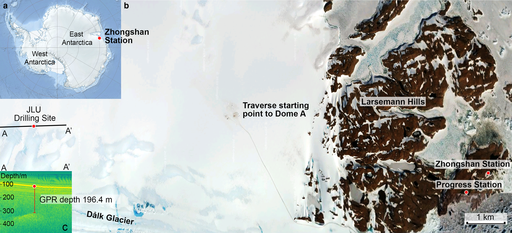
Fig. 10. Drilling-operation area: (a) map of Antarctica, showing the location of Zhongshan Station; (b) Google Map satellite image of the area near Zhongshan Station; (c) ground-penetrating radar profile through JLU drilling site obtained via ‘Snow Eagle’ airborne radar servicing.
Unfortunately, on 19 January 2019, the Chinese icebreaker research ship Xuelong hit a small iceberg in Amundsen Sea, and the ship plating was slightly deformed. CHINARE decided to shut down all oceanographic observations and shorten seasonal studies by 3 weeks. Thus, all drilling operations were conducted under severe time constraints.
After short preparations, dry drilling was commenced on 23 January 2019 using an IBED with an auger core barrel (Fig. 11). A total of 29 runs were performed to penetrate the upper ice layers to a depth of 17.4 m; the average ROP was 4.2 m h−1. The ground operation was time-consuming, mainly because of problems with the removal of the chip chamber. The reason for these problems was the high temperature (~3–4°C) at the site, which caused the melting and refreezing of ice chips.
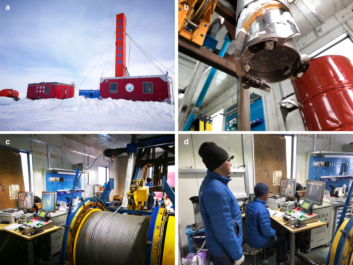
Fig. 11. Drilling operations at the JLU drilling site in the vicinity of Zhongshan Station, East Antarctica: (a) drilling camp; (b) auger version of the IBED with the ice core; (c) drilling winch and control desk; (d) drilling process monitoring.
The measured density of the core in upper interval was 880 kg m−3 on average, indicating that there was no permeable snow/firn layer. Thus, all snowfall in the area was counteracted by melting or sublimation. As the hole was impermeable, the reaming and casing installation was skipped. The hole was filled with Jet A-1 fuel, and drilling was continued using the IBED with bottom reverse circulation. A total of 282 runs were performed to penetrate the ice, including nine runs without a core recovered.
Throughout the drilling, the short version of the IBED with a 1.0 m-long core barrel was used, because the ground maintenance of the drill with the 2.4 m-long core barrel was time-consuming, and time limitations did not allow the improvement of the surface servicing. Staggered cutters and straight-blade cutters were both used for ice coring. With the same cutting load, the staggered cutters yielded a far better performance for cutting the ice and circulating the ice chips. With the staggered cutters, the penetration was smoother, and almost all of the ice chips were collected in the chip chamber.
Down to a depth of 94 m, the average ROP was only 2.5 m h−1, because of the lack of experience of the drill operators (Fig. 12a). After the IBED driving system and transducer of the winch were changed, it was possible to drill at a higher rate of 7–7.5 m h−1. The motor current increased slightly (in the range of 4.6–5.2 A) with the increasing depth (Fig. 12b), while the motor voltage remained stable (~400 V).
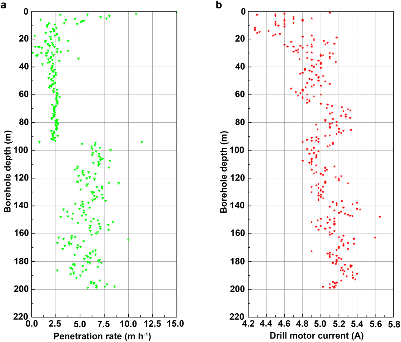
Fig. 12. (a) ROP and (b) motor current with respect to the drilling depth.
The average core length per run was 0.68 m (Fig. 13). The quality of the core was good, with 1–3 pieces obtained in each run. Unfortunately, in several runs, the core was severely broken because of clogging due to chips. Ice chips were collected fully inside the chip chamber, except on several occasions where the chips blocked the clearance between the ice core and the inner core barrel. The reason for this was the defective connection between the inner shaft of the pump and the outer shaft of the gearing reducer.
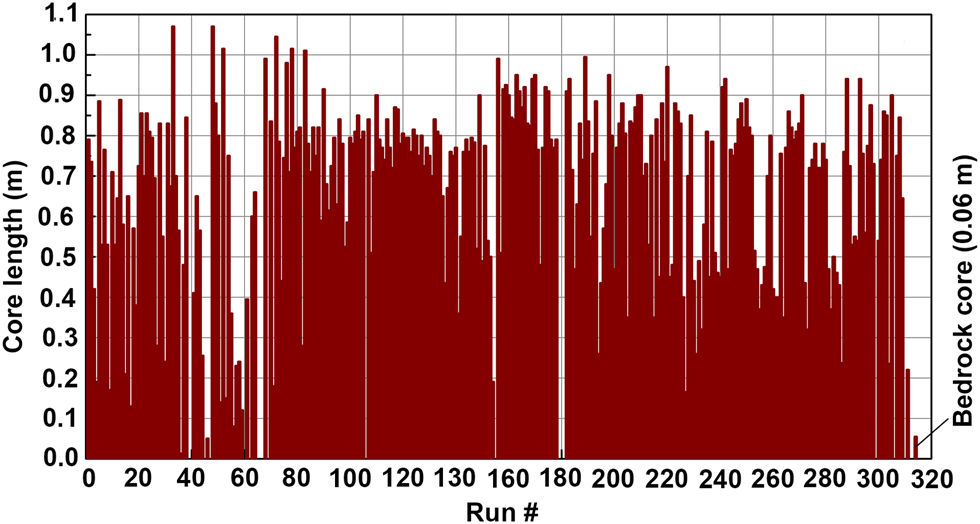
Fig. 13. Length of the core for each run (a total of 313 runs were performed).
During the first 9 d, drilling was generally performed in one shift by four people working 15–18 h d−1. During the last 10 d, drilling was performed in two shifts by six people working around the clock. The average core-production rate was 11 m d−1, with maximum production of 25 m d−1 in the interval of 112.37–137.28 m (Fig. 14).
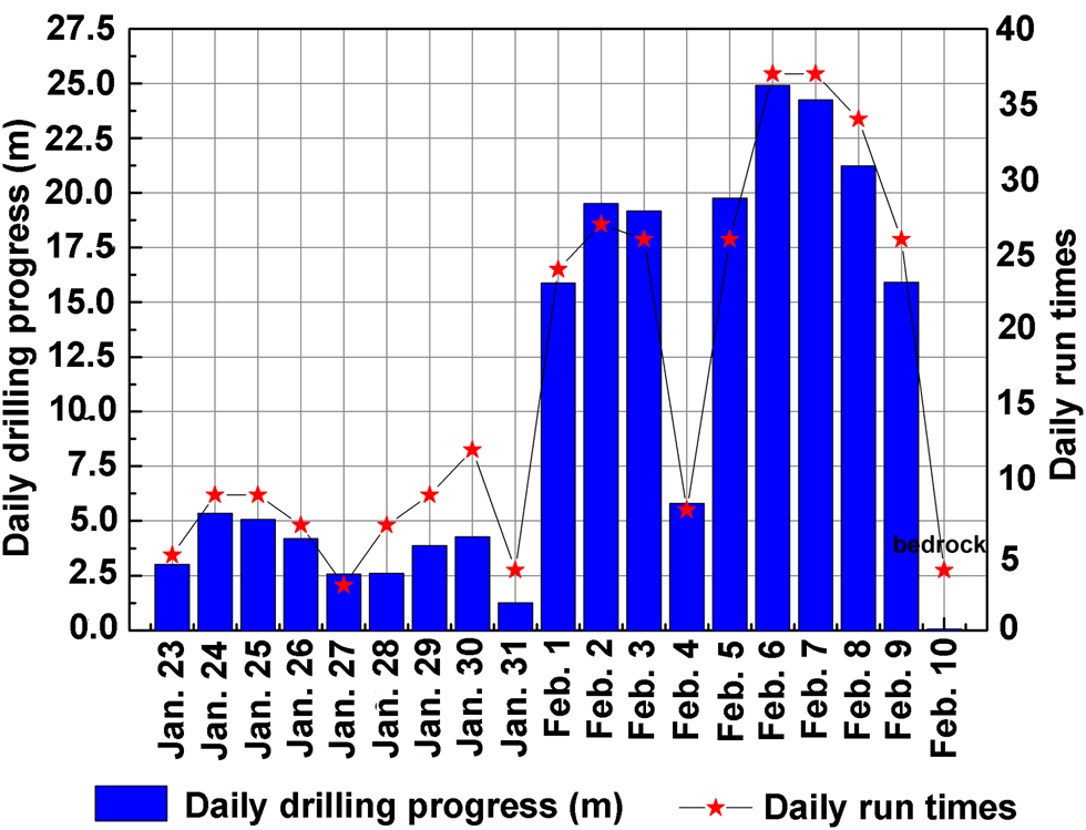
Fig. 14. Daily drilling progress and daily run numbers.
At a depth of 190.75 m, the first small black particles were found in the recovered ice core. At greater depths, the content of impurities increased; the entrained debris consisted predominantly of fine-grained yellow-colored inclusions – mainly silt, with some small rock fragments <8 mm in size. Use of the ice-drill version of the IBED was stopped at a depth of 197.83 m when the cutters were broken, possibly by hitting bedrock. This depth was close to the ice thickness determined via radar measurements (196.4 m). The ice-drill head was replaced with the PDC drill bit, which was used to recover a 0.22 m-long debris-containing ice core (Fig. 15a). After an attempt to continue drilling with the PDC drill bit proved fruitless, the bedrock version of the IBED was activated. The drill was equipped with an additional 100 kg deadweight and a single-core barrel with a toothed impregnated drill bit.

Fig. 15. Drilling to the bed of the Antarctic ice sheet: (a) near-bottom basal ice core; (b) bedrock core and impregnated diamond drill bit.
Finally, on 10 February 2019, a 6 cm-long core of the bedrock was recovered (Fig. 15b). The mineral material was brown-yellow, supposedly containing metamorphosed gneiss, and appeared different from outcrops near Zhongshan Station. Unfortunately, in the next run, the drill became stuck during tripping before coring at a depth of ~197 m. When 40 L of a glycol water solution with a temperature of ~60°C was poured into the borehole, the drill was successfully recovered to the surface after 2 h. However, nothing was found inside the core barrel, except dust and rock cuttings near the windows of the diamond drill bit. Unfortunately, no further drilling was performed, because logistics forced an end to the tests. Owing to time constraints, the drilling team had no chance to continue experiments for bedrock drilling and borehole temperature logging.
The final depth of the borehole was 198.11 m. A total of 18 d was used to penetrate the ice sheet, and 1 d was used to switch to the bedrock-drilling mode. In total, 1994 L of Jet A-1 was poured into the hole, including the liquid recovered with the drill. The liquid level was kept at a distance of 20 m above the borehole bottom. The average drilling-fluid consumption was ~10 L m−1.
Because of the improvement of the drilling technology and the experience gained, the time per run was reduced during the test, although the time for tripping increased. Comparing Run #57 with Run #292 (at the beginning and end of the drilling), the ratio of the penetration time to the total run time decreased from 36 to 20%, and the ratio of the surface operation time to the total run time decreased from 45 to 36%.
8. Future plans
All the cores retrieved in Antarctica were sealed in a plastic jacket and placed in thermally insulated foam boxes with sizes of 122 × 45 × 35 cm. A total of 39 boxes were packed and shipped to China in a cold container on the research ship Xuelong. Recently, the boxes containing the cores were stored in a commercial cold room in Changchun at a temperature of −18°C. The detailed ice-core and bedrock-core research plan is still under development. Blue-ice areas, where peculiar dynamics can preserve old layers, basal ice and bedrock, can provide valuable information regarding Earth's paleo-environment.
Laboratory and field tests of the IBED were successfully performed, and drilling at other sites is planned as soon as full financial and logistical support is obtained for the projects. There are several potential drilling sites that are presently under discussion. The anticipated area of drilling operations lies in the central and eastern part of East Antarctica, between Zhongshan Station at the coast and Kunlun Station at the highest point of the Antarctic Plateau that is connected with the network of CHINARE surface traverses.
One possible site is located on the blue-ice spot ~20 km south of Zhongshan Station, where CHINARE plans to construct an ice airport. Ice-core drilling and borehole logging at this site will definitely help to monitor how ice flows in the area and determine where crevasses are likely to form. Research at the site would also allow the next level of IBED testing, because the ice there is 600–800 m thick – substantially thicker than the ice that we drilled through in the previous field tests.
Another interesting feature in this region is the Grove Mountains (GM) located on the right coast of the Lambert Rift, 450 km south of Zhongshan Station. Although the GM expose a group of isolated nunataks, many aspects of the subglacial geology are not fully understood. This project is multidisciplinary and is focused on (1) investigation of the origin of and evaluation of the GM, which are attributed to a single high-temperature granulite facies tectonic event that occurred ~530–550 Ma ago; (2) investigation of the oldest blue-ice outcrops that were previously discovered in this area; and (3) investigation of the cosmogenic surface exposure dating of the ice-sheet bed.
To date the exposure of the ice-sheet bed, 4–5 boreholes 100–500 m deep must be drilled. If sites are carefully chosen, there is potential to record the length of time for which the bedrock has remained covered by ice. Bedrock samples can provide information regarding the last time that the ice sheet had retreated sufficiently to expose the bed at that site. By obtaining samples from multiple sites, data regarding the last exposure of the bedrock can be used to elucidate the evolution of the ice sheet, with emphasis on the thickness and extent of the ice sheet over time.
Perhaps, the most interesting application of the developed drilling technology is the investigation of the Gamburtsev Subglacial Mountains (GSM) located in the central part of East Antarctica. Modern-day remote-sensing technology and 3-D modeling revealed a very jagged landscape of the GSM. It was found that the GSM are approximately equal in size to the European Alps, and their sharp peaks and valleys are remarkably similar to those of the Alps. The GSM have become the subject of great scientific interest because the mechanism driving the uplift of the range, which resembles younger mountain ranges in shape, in the middle of the old Antarctic Plate, where such processes have not occurred at least in the last 100 million years, is unknown. The only method for determining the age and origin of the GSM is direct observation of the ice-sheet bed via drilling. However, penetrating >1 km of ice while working in extreme cold, at high elevation and far from a major established research base is extremely difficult. Thus, drilling at the GSM may require extensive preparations.
Supplementary material
The supplementary material for this article can be found at https://doi.org/10.1017/aog.2020.38.
Acknowledgements
This research was supported by the National Science Foundation of China (project No. 41327804) and the Program for JLU Science and Technology Innovative Research Team (Project No. 2017TD-24). We thank CHINARE for logistical and financial support of the field operations in Antarctica. The project would not be accomplished without the continuous support and valuable help of Bo Sun, Head of the 35th CHINARE; Fuhai Wei, Vice-Head of the 35th CHINARE; Hongqiao Hu, Leader of Zhongshan Station; Zhaohui Shang, Xu Yao and Tao Wang, leaders of the inland team; and the Snow Eagle aircraft team members, including Xiaosong Shi, Xiangbin Cui, Changwei Hou, Xiaowen Liao, Gan Su, Duanran Zhao, Qingzhong Yao, Gang Qiao, Lin Li and Yukai Zhao. We are grateful to Sergey Popov (Polar Marine Geosurvey Expedition, Russia) and his radio-echo sounding team, who assisted in the selection of the location of the drilling site. We also thank the teachers, engineers and postgraduate students of the Polar Research Center of JLU for their hard work in testing the drill and solving various problems. We greatly appreciate fruitful suggestions, useful comments and editing from Scientific Editor K. Slawny (US Ice Drilling Program) and anonymous reviewers.


 Open access