


1. INTRODUCTION
The Position and Orientation System (POS) is a special Strapdown Inertial Navigation System (SINS)/Global Positioning System (GPS). Compared with the conventional SINS/GPS integrated system, POS can provide position and orientation with greater accuracy and frequency from the airborne sensor; thus, it has become one of the key technologies in airborne remote sensing.
SINS alignment is an important process in determining the angular relationship between the navigation frame and body frame. Thus, initial alignment is critical if precision navigation is to be achieved. In-Flight Alignment (IFA) is defined as in-flight estimates of attitude errors between navigation frame and body frame.
In a number of cases, an Inertial Navigation System (INS) is to be aligned under conditions where external course information is unstable, which makes it necessary to take account of the nonlinear character of the problem. Therefore, the large-heading-error-model is adopted to describe nonlinearity during IFA (Kong et al., Reference Kong, Nebot and Durrant-Whyte1999; Scherzinger, Reference Scherzinger1996; Scherzinger and Reid, Reference Scherzinger and Reid1994).
In recent years, the problems of IFA based on nonlinear filter of INS alignment algorithms have been considered in a great number of publications (Dmitriyev et al., Reference Dmitriyev, Stepanov and Shepel1997; Fang and Yang, Reference Fang and Yang2011; Han and Wang, Reference Han and Wang2009; Park et al., Reference Park, Kim and Kang2006).
The Extended Kalman Filter (EKF) linearises the nonlinear models by first-order Taylor approximations of state transition, so that the traditional linear Kalman filter can be applied. Further, an EKF is employed in IFA (Fang and Yang, Reference Fang and Yang2011). However, its inadequacies, such as a vast calculation of matrix differentiation and higher-order truncation errors, restrict its wide application. In addition, the larger the initial heading error, the more inaccurate is the performance of the EKF.
These EKF drawbacks can be overcome by using an Unscented Kalman Filter (UKF) (Park et al., Reference Park, Kim and Kang2006). A UKF is based on the Unscented Transformation (UT), which is founded on the concept that an approximation of a probability distribution is easier than that of an arbitrary nonlinear function (Julier and Uhlmann, Reference Julier and Uhlmann2004). However the UT has both a local and a global sampling problem. So, modified UKFs are proposed to solve this issue (Hong et al., Reference Hong, Lee and Park2004; Kim and Park, Reference Kim and Park2006; Kim and Park, Reference Kim and Park2010). The more advanced techniques generally improve estimation accuracy, but they often perform at the expense of further complications in implementation and an increased computational burden (NØrgaard et al., Reference NØrgaard, Poulsen and Ravn2000). Meanwhile, other technologies are also applied in an IFA (Han and Wang, Reference Han and Wang2009; Hao et al., Reference Hao, Xiong and Hu2006; Hong et al., Reference Hong, Han, Lee and Paik2010; Wang et al., Reference Wang, Cai, Chen, Han and Ji2011; Yu et al., Reference Yu, Lee and Park2004), but with a complex procedure.
The Divided Difference Filter (DDF), which is based on polynomial approximations of the nonlinear transformations, obtained with particular multidimensional extension of Stirling's interpolation formula, is simple to implement as no derivatives are needed and it can achieve better covariance estimates compared to EKF (Ali and Ullah Baig Mirza, Reference Ali and UllahBaig Mirza2011; Setoodeh et al., Reference Setoodeh, Khayatian and Farjah2007).
However, the estimation performance depends on correct statistical characterisation of the process and measurement noise covariance matrices (Q and R, respectively). For IFA of POS, GPS measurement noise will change with aircraft manoeuvre or electromagnetic interference and other factors. Unstable GPS measurement disturbance will inevitably degrade the performance of the filter with the fixed R matrix (Fang and Yang, Reference Fang and Yang2011).
In this paper, an Adaptive Second-Order Divided Difference filter (ADD2) based on innovation covariance estimation is proposed which introduces the covariance estimation of innovation into the calculation of the Second-order Divided Difference filter (DD2) gain matrix directly, instead of adjusting the R matrix. Then, the proposed ADD2 is applied in the IFA of the airborne POS with a large initial heading error. Moreover the accuracy of EKF and DD2 are analysed. Finally, experiments are carried out to validate the effectiveness of ADD2 compared with Adaptive Extended Kalman Filter (AEKF) with large heading error under unstable GPS measurement.
The remainder of this paper is organized as follows. Section 2 presents the proposed ADD2 algorithm based on innovation covariance estimation. Section 3 extends the application of the ADD2 to the IFA of airborne POS, and then the performance of the proposed scheme is evaluated in Section 4. The Conclusions are set out in Section 5.
2. ADAPTIVE DD2 ALGORITHM BASED ON INNOVATION COVARIANCE ESTIMATION
The innovation of the filter can be observed directly. So by observing the covariance of the innovation sequence, the filter performance can be corrected to some extent. Generally, the innovation of the filter should be a white noise sequence with zero mean. However, an inexact knowledge of the process and/or measurement noise will lead to complex statistical characteristics of the innovation sequence. Therefore, through the innovation covariance estimation, the process noise covariance matrix Q and/or measurement noise covariance matrix R can be adjusted adaptively to prevent the divergence of the filter (Bian et al., Reference Bian, Jin and Tian2006). In this paper, an adaptive DD2 algorithm based on Innovation-based Adaptive Estimation (IAE) is discussed, considering the incomplete or change information of the measurement noise. Consider a nonlinear system with a nonlinear state model and a linear measurement model:
 $$\left\{ {\matrix{ {{\bf \dot x}(t) = {\bf f} \left( {{\bf x},t} \right) + {\bf w}(t)} \cr {{\bf y}(t) = {\bf H}(t){\bf x}(t) + {\bf v}(t)} \cr}} \right.$$
where:
x(t) is the state vector.
f is the nonlinear function.
w(t) is the system noise with covariance Q(t).
y(t) is the measurement vector.
H is the linear function.
v(t) is the measurement noise with covariance R(t).
2.1. The Basic Structure of the DDF
The DDF adopts an alternative linearization method, called a divided difference approximation, in which derivatives are replaced by functional evaluations and an easy expansion of the nonlinear functions to higher order terms is possible.
The basic DD2 filter is described as follows (NØrgaard et al., Reference NØrgaard, Poulsen and Ravn2000).
2.1.1. Initialization
The initial state vector  ${\bf \hat x}_0 $ and the square root matrix
  ${\bf \hat S}_x $ of its covariance P0 are given as:
 $${\bf P}_0 = {\bf \hat S}_x {\bf \hat S}_x^T, \quad {\bf Q}_0 = {\bf \hat S}_w {\bf \hat S}_w^T $$$$
2.1.2. The a priori Update
For the a priori update of the state estimate, the improved state estimate is obtained:
 $${\bf \bar x}_k = \displaystyle{{h^2 - n_x - n_w} \over {h^2}} {\bf f}({\bf \hat x}_{k - 1} ) + \displaystyle{1 \over {2h^2}} \sum\limits_{\,p = 1}^{n_x} {\left[ {{\bf f}({\bf \hat x}_{k - 1} + h{\bf \hat s}_{x,p} ) + {\bf f} ({\bf \hat x}_{k - 1} - h{\bf \hat s}_{x,p} )} \right]} $$
where:
n x and n w are dimension of state and process noise, respectively.
h is the selection of interval length, and assuming that the estimation errors are Gaussian and unbiased, one should set h 2 = 3.
The triangular Cholesky factor of the a priori covariance is obtained by Householder transformation of the following compound matrix:
 $${\bf \bar S}_x (k) = \left[ {\matrix{ {{\bf S}_{x\hat x}^{(1)} (k - 1)} & {{\bf S}_{xw}^{(1)} (k - 1)} & {{\bf S}_{x\hat x}^{(2)} (k - 1)} & {{\bf S}_{xw}^{(2)} (k - 1)} \cr}} \right]$$
 $$\openup6\left\{ {\matrix{ {{\bf S}_{x\hat x}^{(1)} (k) = \left\{ {{\bf S}_{x\hat x}^{(1)} (k)_{(i,j)}} \right\} = \left\{ {{{\left( {{\bf f}_i ({\bf \hat x}_k + h{\bf \hat s}_{x,j} ) + {\bf f}_i ({\bf \hat x}_k - h{\bf \hat s}_{x,j} )} \right)} / {2h}}} \right\}} \hfill \cr {{\bf S}_{xw}^{(1)} (k) = \left\{ {{\bf S}_{xw}^{(1)} (k)_{(i,j)}} \right\} = \left\{ {{{\left( {{\bf f}_i ({\bf \hat x}_k + h{\bf \hat s}_{w,j} ) + {\bf f}_i ({\bf \hat x}_k - h{\bf \hat s}_{w,j} )} \right)} / {2h}}} \right\}} \hfill \cr {{\bf S}_{x\hat x}^{(2)} (k) = \left\{ {{{\sqrt {h^2 - 1} \left( {{\bf f}_i ({\bf \hat x}_k + h{\bf \hat s}_{x,j} ) + {\bf f}_i ({\bf \hat x}_k - h{\bf \hat s}_{x,j} ) - 2{\bf f}_i ({\bf \hat x}_k )} \right)} / {2h^2}}} \right\}} \hfill \cr {{\bf S}_{xw}^{(2)} (k) = \left\{ {{{\sqrt {h^2 - 1} \left( {{\bf f}_i ({\bf \hat x}_k + h{\bf \hat s}_{w,j} ) + {\bf f}_i ({\bf \hat x}_k - h{\bf \hat s}_{w,j} ) - 2{\bf f}_i ({\bf \hat x}_k )} \right)} / {2h^2}}} \right\}} \hfill \cr}} \right.$$
where:
subscript j denotes the jth column of related matrix, and similarly for the other factors.
2.1.3. The a posteriori Update
The a priori estimate of the output and its covariance is calculated by the following equations:
 $${\bf \hat x}_k = {\bf \bar x}_k + {\bf K}_k ({\bf y}_k - {\bf \bar y}_k )$$
 $${\bf \bar y}_k = \displaystyle{{h^2 - n_x - n_v} \over {h^2}} {\bf H}_k \cdot {\bf \bar x}_k + \displaystyle{1 \over {2h^2}} \sum\limits_{p = 1}^{n_x} {\left( {{\bf H}_k \cdot ({\bf \bar x}_k + h{\bf \hat s}_{x,p} ) + {\bf H}_k \cdot ({\bf \bar x}_k - h{\bf \hat s}_{x,p} )} \right)} $$
where:
n v is the dimension of measurement,
and:
 $${\bf K}_k = {\bf P}_{xy} (k)\left[ {{\bf S}_y (k){\bf S}_y^T (k)} \right]^{ - 1} $$
 $${\bf P}_{xy} (k) = {\bf \bar S}_x (k){\bf S}_{y\bar x}^{(1)} (k)^T $$
The correlative parameters are obtained using the following equations:
 $${\bf S}_y (k) = \left[ {\matrix{ {{\bf S}_{y\bar x}^{(1)} (k - 1)} & {{\bf S}_{yv}^{(1)} (k - 1)} & {{\bf S}_{y\bar x}^{(2)} (k - 1)} & {{\bf S}_{yv}^{(2)} (k - 1)} \cr}} \right]$$
 $$\openup6pt\left\{ {\matrix{ {{\bf S}_{y\bar x}^{(1)} (k) = \left\{ {{\bf S}_{y\bar x}^{(1)} (k)_{(i,j)}} \right\} = \left\{ {{{\left( {{\bf H} _i \cdot ({\bf \bar x}_k + h{\bf \bar s}_{x,j} ) + {\bf H} _i \cdot ({\bf \bar x}_k - h{\bf \bar s}_{x,j} )} \right)} / {2h}}} \right\}} \hfill \cr {{\bf S}_{yv}^{(1)} (k) = \left\{ {{\bf S}_{yv}^{(1)} (k)_{(i,j)}} \right\} = \left\{ {{{\left( {{\bf H} _i \cdot ({\bf \bar x}_k + h{\bf s}_{v,j} ) + {\bf H} _i \cdot ({\bf \bar x}_k - h{\bf s}_{v,j} )} \right)} / {2h}}} \right\}} \hfill \cr {{\bf S}_{y\bar x}^{(2)} (k) = \left\{ {{{\sqrt {h^2 - 1} \left( {{\bf H} _i \cdot ({\bf \bar x}_k + h{\bf \bar s}_{x,j} ) + {\bf H} _i \cdot ({\bf \bar x}_k - h{\bf \bar s}_{x,j} ) - 2{\bf H} _i \cdot ({\bf \bar x}_k )} \right)} / {2h^2}}} \right\}} \hfill \cr {{\bf S}_{yv}^{(2)} (k) = \left\{ {{{\sqrt {h^2 - 1} \left( {{\bf H} _i \cdot ({\bf \bar x}_k + h{\bf s}_{v,j} ) + {\bf H} _i \cdot ({\bf \bar x}_k - h{\bf s}_{v,j} ) - 2{\bf H} _i \cdot ({\bf \bar x}_k )} \right)} / {2h^2}}} \right\}} \hfill \cr}} \right.$$
 $${\bf R} = {\bf S}_v {\bf S}_v^T $$
The a posteriori update of the estimation error covariance is:
 $$\eqalign{ {\bf \hat P}_x (k) =&\,\, {\bf \bar S}_x (k) - {\bf K}_k {\bf S}_{y\bar x}^{(1)} (k)\left( {{\bf \bar S}_x (k) - {\bf K}_k {\bf S}_{y\bar x}^{(1)} (k)} \right)^T + {\bf K}_k {\bf S}_{yv}^{(1)} (k)\left( {{\bf K}_k {\bf S}_{yv}^{(1)} (k)} \right)^T \cr & + {\bf K}_k {\bf S}_{y\bar x}^{(2)} (k)\left( {{\bf K}_k {\bf S}_{y\bar x}^{(2)} (k)} \right)^T + {\bf K}_k {\bf S}_{yv}^{(2)} (k)\left( {{\bf K}_k {\bf S}_{yv}^{(2)} (k)} \right)^T} $$
This has the Cholesky factor:
 $${\bf \hat S}_x (k) = \left[ {\matrix{ {{\bf \bar S}_x (k) - {\bf K}_k {\bf S}_{y\bar x}^{(1)} (k)} & {{\bf K}_k {\bf S}_{yv}^{(1)} (k)} & {{\bf K}_k {\bf S}_{y\bar x}^{(2)} (k)} & {{\bf K}_k {\bf S}_{yv}^{(2)} (k)} \cr}} \right]$$
2.2. Adaptive DD2 Algorithm Based On Innovation Covariance Estimation
Innovation information is defined as  ${\bf z}_k = {\bf y}_k - {\bf \bar y}_k $, and according to Shademan and Sharifi, (Reference Shademan and Janabi-Sharifi2005), its covariance estimation can be obtained as follows:
 $$D({\bf z}_k ) = \displaystyle{1 \over N}\sum\limits_{i = i0}^k {\left[ {{\bf z}_k {\bf z}_k^T} \right]} $$
where:
N is the window size over which the moving average of zkzkT is taken as the estimation of the innovation covariance.
The theoretical innovation covariance of DD2 with a fixed R should be P y(k) = Sy(k)Sy(k)T, where Sy(k) is calculated as Equation (10); however, it cannot reflect the variations of the external measurement noise with a fixed R and will decrease the filter performance when the statistical characteristic of the measurement noise is changed.
An adaptive strategy based innovation covariance estimation is introduced. When the innovation covariance estimation differs from the theoretical value, this hints that the statistical characteristic of the measurement noise is changed. Then, the dissimilarity between them can be used to adjust the measurement noise covariance matrix R.
 $${\bf P}_y (k) = E\left[ {{\bf z}_k {\bf z}_k^T} \right] = \displaystyle{1 \over N}\sum\limits_{i = i0}^k {\left[ {{\bf z}_k {\bf z}_k^T} \right]} $$
The calculation of Kk is:
 $${\bf K}_k = {\bf P}_{xy} (k)\left[ {{\bf S}_y (k){\bf S}_y^T (k)} \right]^{ - 1} = {\bf P}_{xy} (k)\left[ {{\bf P}_y (k)} \right]^{ - 1} $$
Then, if measurement noise increases, the estimated innovation covariance will also increase. Moreover, the filter gain Kk will decrease, which means that it depends less on measurement information.
In this paper, estimation of innovation covariance is introduced into the calculation of the gain matrix Kk directly, and the ADD2 algorithm is as follows:
2.2.1. Initialization
The initial state vector  ${\bf \hat x}_0 $ and the square root matrix
  ${\bf \hat S}_x $ of its covariance P0 are given as:
 $${\bf P}_0 = {\bf \hat S}_x {\bf \hat S}_x^T, \quad {\bf Q}_0 = {\bf \hat S}_w {\bf \hat S}_w^T $$$$
2.2.2. The a priori Update
For the a priori update of the state estimate, the improved state estimate is obtained as:
 $${\bf \bar x}_k = \displaystyle{{h^2 - n_x - n_w} \over {h^2}} {\bf f}({\bf \hat x}_{k - 1} ) + \displaystyle{1 \over {2h^2}} \sum\limits_{\,p = 1}^{n_x} {\left[ {{\bf f}({\bf \hat x}_{k - 1} + h{\bf \hat s}_{x,p} ) + {\bf f} ({\bf \hat x}_{k - 1} - h{\bf \hat s}_{x,p} )} \right]} $$
2.2.3. The a posterior Update
The a posterior update is:
 $${\bf \bar y}_k = \displaystyle{{h^2 - n_x - n_v} \over {h^2}} {\bf H}_k \cdot {\bf \bar x}_k + \displaystyle{1 \over {2h^2}} \sum\limits_{\,p = 1}^{n_x} {\left( {{\bf H}_k \cdot ({\bf \bar x}_k + h{\bf \hat s}_{x,p} ) + {\bf H}_k \cdot ({\bf \bar x}_k - h{\bf \hat s}_{x,p} )} \right)} $$
 $${\bf z}_k = {\bf y}_k - {\bf \bar y}_k $$
then:
the estimation of the innovation covariance is:
 $${\bf P}_y (k) = E\left[ {{\bf z}_k {\bf z}_k^T} \right] = \displaystyle{1 \over N}\sum\limits_{i = i0}^k {\left[ {{\bf z}_k {\bf z}_k^T} \right]} $$
and:
the gain Kk is obtained as:
 $$\openup3pt\eqalign{& {\bf K}_k = {\bf P}_{xy} (k)\left[ {{\bf S}_y (k){\bf S}_y^T (k)} \right]^{ - 1} = {\bf P}_{xy} (k)\left[ {{\bf P}_y (k)} \right]^{ - 1} \cr & {\bf \hat x}_k = {\bf \bar x}_k + {\bf K}_k {\bf z}_k} $$$$
In the next section, the proposed ADD2 is used in the IFA of POS with large initial heading error.
3. IFA WITH LARGE INITIAL HEADING ERROR USING ADD2
3.1. Main Coordinate Frames
3.1.1. i-frame (Inertial Frame)
The inertial frame located at the centre of the Earth (point O) is non-rotating with respect to the fixed stars. Its xi-axis is in the equatorial plane and points to the vernal equinox, its zi-axis is normal to that plane, and its yi-axis completes the right-handed system.
3.1.2. e-frame (Earth frame)
The Earth frame located at the centre of the Earth has its ze-axis through the true North pole and its xe-axis through the intersection of the prime meridian (0° longitude) and the Equator (0° latitude).
3.1.3. n-frame (Navigation Frame)
The navigation frame is a local-level frame, located at the surface of the Earth (point P). Its xn-axis points eastward, its yn-axis points northward, and its zn-axis is parallel to the upward vertical.
3.1.4. b-frame (Body Frame)
The body frame is fixed to the vehicle and is located at the centroid of the vehicle. Its yb-axis along the longitudinal axis of the vehicle points forward, and its xb-axis points to the right side. Its zb-axis completes the right-handed system.
3.1.5. p-frame (Platform Frame)
The platform frame is also located at point P and has an angle error with respect to the n-frame.
3.2. State Model
In this paper, a state vector of 13 dimensions is chosen, including level position error 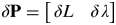 $\delta {\bf P} = \left[ {\matrix{ {\delta L} & \delta \cr} \lambda} \right]$, level velocity error
 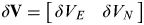 $\delta {\bf V} = \left[ {\matrix{ {\delta V_E} & {\delta V_N} \cr}} \right]$, attitude error
 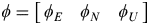 $\phi = \left[ {\matrix{ {\phi _E} & {\phi _N} & {\phi _U} \cr}} \right]$, and inertial sensors error
 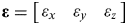 ${\bf \varepsilon} = \left[ {\matrix{ {\varepsilon _x} & {\varepsilon _y} & {\varepsilon _z} \cr}} \right]$,
 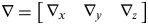 $\nabla = \left[ {\matrix{ {\nabla _x} & {\nabla _y} & {\nabla _z} \cr}} \right]$.
Subscripts E, N, U denote the East, North, and Up components in the n-frame, respectively, and subscripts x, y, and z denote the right, front, and up components in the b-frame, respectively.
The large heading error model (Yu et al., Reference Yu, Lee and Park1999) of the SINS will be used in this paper for nonlinear IFA, which can be separated into a linear part and a nonlinear part as follows:
 $$\openup4\left[ {\matrix{ {\delta {\bf \dot P}} \cr {\delta {\bf \dot V}} \cr {\dot \phi} \cr {{\bf \dot \varepsilon}} \cr {\dot \nabla} \cr}} \right] = \left[ {\matrix{ {{\bf F}_1} & {{\bf F}_2} & {\bf 0} & {\bf 0} & {\bf 0} \cr {\bf 0} & {{\bf F}_3} & {\bf 0} & {\bf 0} & {{\bf C}_b^p} \cr {\bf 0} & {\bf 0} & {\bf 0} & {{\bf C}_b^p} & {\bf 0} \cr {\bf 0} & {\bf 0} & {\bf 0} & {\bf 0} & {\bf 0} \cr {\bf 0} & {\bf 0} & {\bf 0} & {\bf 0} & {\bf 0} \cr}} \right]\left[ {\matrix{ {\delta {\bf P}} \cr {\delta {\bf V}} \cr \phi \cr {\bf \varepsilon} \cr \nabla \cr}} \right] + \left[ {\matrix{ {\bf 0} \cr {({\bf C}_n^p - {\bf I}){\bf C}_b^n {\bf f}^b - \delta {\bf \omega} _{en}^n \times {\bf V}} \cr {({\bf I} - {\bf C}_n^p ){\bf \omega} _{in}^n - \delta {\bf \omega} _{en}^n} \cr {\bf 0} \cr {\bf 0} \cr}} \right]$$
where:
 $$\openup4{\bf F}_1 = \left[ {\matrix{ 0 & 0 \cr {{{V_E \tan L} / {\left( {(R_N + h)\cos L} \right)}}} & 0 \cr}} \right],$
 $$\openup4{\bf F}_2 = \left[ {\matrix{ 0 & {{1 / {\left( {R_{\rm M} + h} \right)}}} \cr {{{\sec L} / {\left( {R_{\rm N} + h} \right)}}} & 0 \cr}} \right],$
F3 is the first two rows of − (2Ωien + Ωenn).
The definition of some other parameter and constant are referenced in Yu et al. (Reference Yu, Lee and Park1999).
3.3. Measurement Model
The level position and velocity errors are taken as observations for the filter. This can be obtained from the errors between the SINS and the GPS. Therefore, the measurement model is linear and can be written as:
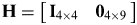
 $${\bf z}(t) = \left[ {\matrix{ {L_{{\rm INS}} - L_{{\rm GPS}}} \cr {\lambda _{{\rm INS}} - \lambda _{{\rm GPS}}} \cr {V_{E\,{\rm INS}} - V_{E\,{\rm GPS}}} \cr {V_{N\,{\rm INS}} - V_{N\,{\rm GPS}}} \cr}} \right] = {\bf Hx}(t) + {\bf v}(t)$$
where:
 ${\bf H} = \left[ {\matrix{ {{\bf I}_{4 \times 4}} & {{\bf 0}_{4 \times 9}} \cr}} \right]$ is the observation matrix.
When applying the proposed ADD2 in IFA, the dimension effect of accelerometers is compensated first, then the position and velocity differences between the SINS and the GPS after lever-arm compensation are taken as the measurements for the filter. The estimated errors of position, velocity and attitude are fed back directly. However, for the inertial sensor errors, feeding them back directly may cause additional errors to the filter due to their poor observability. Since the manoeuvre during the IFA can improve the observability of these states, inertial sensor errors are simply fed back to the SINS when the IFA is finished. A block diagram of IFA based on ADD2 is shown in Figure 1.

Figure 1. Block diagram of IFA based on ADD2.
3.4. Attitude Error Based on EKF and DD2
The DD2 is able to achieve better estimation accuracy of IFA under large heading error than EKF. Using the indirect feedback Kalman filter, the estimated values of the states tend to be always zero (Park et al., Reference Park, Kim and Kang2006). Thus, there exists linearised error. However, we show that the DD2 has less linearized error than EKF.
The attitude error model is given as:
 $$\openup3{\bf C}_p^n = \left[ {\matrix{ {\cos \phi _U} & {\sin \phi _U} & {\phi _N \cos \phi _U + \phi _E \sin \phi _U} \cr { - \sin \phi _U} & {\cos \phi _U} & {\phi _N \sin \phi _U - \phi _E \cos \phi _U} \cr { - \phi _N} & {\phi _E} & 1 \cr}} \right]$$
where:
Cpn is the direction cosine matrix from the p-frame to the n-frame.
Cbp is the direction cosine matrix from the b-frame to the p-frame.
Assuming Cbp = I3 × 3:
 $$\openup3\Delta {\bf C} = \left[ {\matrix{ {1 - \cos \phi _U} & { - \sin \phi _U} & { - \phi _N \cos \phi _U - \phi _E \sin \phi _U} \cr { - \sin \phi _U} & {1 - \cos \phi _U} & { - \phi _N \sin \phi _U + \phi _E \cos \phi _U} \cr {\phi _N} & { - \phi _E} & 0 \cr}} \right]$$
As the linearized point of EKF is ϕ E = ϕ N = ϕ U = 0, the EKF attitude error from Equation (27) is represented as (Park et al., Reference Park, Kim and Kang2006):
 $$\openup3\Delta {\bf C}_{{\rm EKF}} = \left[ {\matrix{ 0 & 0 & 0 \cr 0 & 0 & 0 \cr 0 & 0 & 0 \cr}} \right]$$
And using the matrix trace in Equations (27) and (28), the results are as follows:
 $${\rm tr}(\Delta {\bf C}) = 2 - 2\cos \phi _U $$
 $${\rm tr}(\Delta {\bf C}_{{\rm EKF}} ) = 0$$
The trace difference of EKF is calculated as:
$$\delta {\bf C}_{{\rm EKF}} = {\rm tr}(\Delta {\bf C}) - {\rm tr}(\Delta {\bf C}_{{\rm EKF}} ) = 2 - 2\cos \phi _U = 2\left( {\displaystyle{{\phi _U^2} \over {2!}} - \displaystyle{{\phi _U^4} \over {4!}} + \displaystyle{{\phi _U^6} \over {6!}} - \cdots} \right)$$The ΔCDD2 of DD2 can be deduced as follows:
Considering the attitude covariance matrix pA for convenience:
 $$\openup2\eqalign{\displaylines{\Delta {\bf C}_{{\rm DD2}}& = \displaystyle{1 \over 6}\left[ {\matrix{ {1 - \cos \sqrt {3p_{\phi _U}}} & {\sin \sqrt {3p_{\phi _U}}} & 0 \cr { - \sin \sqrt {3p_{\phi _U}}} & {1 - \cos \sqrt {3p_{\phi _U}}} & 0 \cr 0 & 0 & 0 \cr}} \right]}\hfill\cr&{\hskip-170pt+ \displaystyle{1 \over 6}\left[ {\matrix{ {1 - \cos \left( { - \sqrt {3p_{\phi _U}}} \right)} & {\sin \left( { - \sqrt {3p_{\phi _U}}} \right)} & 0 \cr { - \sin \left( { - \sqrt {3p_{\phi _U}}} \right)} & {1 - \cos \left( { - \sqrt {3p_{\phi _U}}} \right)} & 0 \cr 0 & 0 & 0 \cr}} \right]}\hfill \cr &{\hskip-180pt= \displaystyle{1 \over 3}\left[ {\matrix{ {2 - 2\cos \sqrt {3p_{\phi _U}}} & 0 & 0 \cr 0 & {2 - 2\cos \sqrt {3p_{\phi _U}}} & 0 \cr 0 & 0 & 0 \cr}} \right]}}}\hfill $$
 $${\rm tr}(\Delta {\bf C}_{{\rm DD2}} ) = {{\left( {2 - 2\cos \sqrt {3p_{\phi _U}}} \right)} / 3}$$
 $$\eqalign{\hskip40pt\displaylines{\delta {\bf C}_{{\rm DD2}} =& {\rm tr}(\Delta {\bf C}) - {\rm tr}(\Delta {\bf C}_{{\rm DD2}} )\hskip-92pt} \cr &{= {{\left( {2 - 2\cos \phi _U} \right) - \left( {2 - 2\cos \sqrt {3p_{\phi _U}}} \right)} / 3}} \cr &= \delta {\bf C}_{{\rm UKF}} \approx - \displaystyle{2 \over {4!}}\left( {\phi _U^4 - 3P_{\phi _U} ^2} \right) + \displaystyle{2 \over {6!}}\left( {\phi _U^6 - 9P_{\phi _U} ^4} \right) - \cdots} $$
Equations (31) and (34) show that DD2 error is introduced into the fourth and higher order terms, while the EKF is second and higher. Therefore compared with EKF, the accuracy estimated by DD2 is better with the larger heading error.
4. SIMULATION AND EXPERIMENT
To evaluate the proposed method, simulations and experiments are carried out, then the data are processed using ADD2 and AEKF.The window size in filters is N = 10 (Wang, Reference Wang2000; Wang et al., Reference Wang, Stewart and Tsakiri2000).
4.1 Simulation and Analysis
Simulations are designed based on high precision inertial unit and GPS. The specifications of the system are at Table 1.
Table 1. Specifications of POS.

A general flight trajectory is designed as part of a practical flight with a turning manoeuvre. The trajectory is composed of several segments of flying in line and turning with an attitude manoeuvre. The initial simulation information is listed in Table 2 and the simulation trajectory is shown in Figure 2.

Figure 2. Planning track.
Table 2. Simulation Specifications.

To test the validity of ADD2, keep the statistical characteristic of GPS noise normal for the first 20 seconds, change it four times during the manoeuvre and then revert to normal. The estimation results of ADD2 and AEKF are shown in Figure 3 through Figure 5. Comparison of attitude errors and time consumption in MATLAB® are shown in Table 3.

Figure 3. Estimation of the heading error.

Figure 4. Estimation of the roll error.

Figure 5. Estimation of the pitch error.
Table 3. Attitude Accuracy Comparison.

It can be concluded that ADD2 performance can provide a substantial performance increase over AEKF when measurement noise is changed. Consistent with the preceding analysis, because of the large linearized error of EKF, the estimation errors of AEKF are much higher than ADD2, particularly for the heading error. It can be concluded that the two filters have almost the same computational burden. Thus, it would be effortless for the proposed method to be used in real time.
4.2. Experiment and Analysis
To further validate the algorithm, experiments are carried out with the prototype of the high-accuracy airborne POS (designated TX-F30) developed by BeiHang University, which is comprised of the high-accuracy Fibre Optic Gyro (FOG) Inertial Measurement Unit (IMU) and the NovAtel DL-V3 GPS OEM board. The specifications are listed in Table 4, and the POS is shown in Figure 6. The GPS is adopted in real time processing, while the Carrier-phase Differential GPS (CDGPS) is employed for post processing. Forward filter and backward smoothing is used in post-processing, to gain higher accuracy.

Figure 6. POS TX-F30.

Figure 7. Configuration and car-mounted experiment.
Table 4. Specifications for TX-F30.

4.2.1. Car-Mounted Experiment
The experiments were carried out on the 5th ring road of Beijing; the trajectory is shown in Figure 8, in which the thick line in green of 200 s duration represents the segment used for IFA.

Figure 8. Ground trajectory and segment for IFA.
The alignment results are given in Figures 9 and 10. The results of ADD2 converge more quickly than AEKF, and with higher accuracy.

Figure 9. Curve of attitude during IFA.

Figure 10. Error of attitude during IFA.
The alignment results are given in Table 5. The attitude of ADD2 is more precise than that of AEKF.
Table 5. Alignment Results of IFA in Car-mounted Experiment.

Other than comparison with true initial attitude, there is another way to validate attitude precision. The CDGPS output is taken as a reference to calculate the level position error of SINS with 20 s after IFA with the same initial position. The position differences between the strapdown navigations with different IFA and GPS are in Figure 11.

Figure 11. SINS error of plan position of car-mounted experiment.
The result means that the proposed IFA method can improve the alignment accuracy and reduce the positioning errors (for the SINS only).
4.2.2. Flight Experiment
The POS is used for motion compensation of the X-band airborne InSAR. The aircraft and flight trajectory are shown in Figures 12 and 13, respectively. The thick line in green, which lasts for 450 s, represents the segment used for IFA.

Figure 12. Citation II and equipment installation.

Figure 13. 3-D flight trajectory and Plan Flight-Path of Mapping Area.
The alignment results are given in Figures 14 and 15.

Figure 14. Attitude during IFA.

Figure 15. Error of attitude during IFA.
These experimental results show that both AEKF and ADD2 filters can be adjusted with changes in measurement noise through innovation covariance estimation. However, the ADD2 filter yields the better accuracy. The alignment results are given in Table 6. The ADD2 filter also shows better results.
Table 6. Alignment Result of IFA in the Flight.

The CDGPS output is taken as a reference to calculate the level position error of SINS with 20 s after IFA with the same initial position. The position differences between the strapdown navigation with different IFA and the CDGPS are shown in Figure 16.

Figure 16. SINS error of plan position of the flight.
This result means that the proposed IFA method based on ADD2 can improve alignment accuracy and reduce positioning errors (for SINS only).
5. CONCLUSIONS
To resolve the issue that incorrect knowledge of measurement noise will cause degradation of filter performance, an innovation-covariance estimation-based Adaptive Second-order Divided Difference filter (ADD2) algorithm is proposed. The proposed method is applied to the In-Flight Alignment (IFA) of Fibre Optic Gyro (FOG) - Position and Orientation System (POS) with large initial heading error. The flight experimental results show excellent performance of the filter under the condition variation of characteristic of measurement noise. Compared with an Adaptive Extended Kalman Filter (AEKF), the proposed ADD2 can effectively suppress the impact of unstable Global Positioning System (GPS) measurement noise on state estimation and improve attitude accuracy. Further, the proposed ADD2 has an almost identical computational burden, but much higher estimation precision than AEKF.
ACKNOWLEDGEMENTS
The work described in this paper was supported by the National Basic Research Program of China (2009CB724002), China National Funds for Distinguished Young Scientists (60825305), and the National Natural Science Foundation of China (61104198). The authors thank all members of the Science and Technology on Inertial Laboratory and the Fundamental Science on Novel Inertial Instrument & Navigation System Technology Laboratory, for their useful comments regarding this work.


