


INTRODUCTION
Irradiated graphite is one of the radioactive waste categories that will be generated after decommissioning of the TRIGA research reactor, a reactor in operation at the Institute for Nuclear Research. The principal long-lived radionuclide species present in irradiated graphite are 14C and 36Cl.
First experiments to measure the radionuclide inventory in TRIGA i-graphite were carried out under the CARBOWASTE project (Vulpius et al. Reference Vulpius, von Lensa, Jones, Guy, Comte, Dodaro, Duskesas and Iordache2008). The measured data were complemented with data obtained by modeling, based on the impurity content of the virgin graphite and the irradiation history (Iorgulis et al. Reference Iorgulis, Diaconu, Gugiu and Csaba2013).
The thermal column of the TRIGA Reactor is a graphite block (1716 × 1144 × 710 mm) made up of 98 rectangular graphite cells (12 rows × 8 bricks) in aluminum cladding, which is placed into the reactor pool on the north side of the steady-state core. It was built up in 1985, using sintered graphite blocks with a density of 1.72 g/cm3 and various geometries.
Within the CArbon-14 Source Term (CAST) project, Work Package 5 was particularly dedicated to understand the factors determining release of 14C from irradiated graphite (i-graphite) under geological disposal conditions. The activities proposed to achieve this objective include: determining the 14C inventory and concentration distribution in i-graphites and factors that may control these; measuring the rate and speciation of 14C release to solution and gas from i-graphites in contact with aqueous solutions; and determining the impact of selected waste treatment options on 14C release and relating this to the nature of 14C in i-graphite (Scourse and Williams Reference Scourse and Williams2014). In this paper, experimental data for the 14C inventory in the irradiated graphite from thermal column of the TRIGA 14MW reactor and for the release rate of 14C in alkaline conditions (relevant to the disposal of such radioactive waste utilizing a disposal concept involving a cementitious environment, which aims to reduce radionuclide solubility and enhance sorption), both in terms of total 14C as well as inorganic and organic fractions, are reported.
MATERIALS AND METHODS
Irradiated Graphite Used in the Leaching Tests
Two cylindrical bars originating from a brick extracted and dismantled in 2000 from the thermal column of TRIGA reactor were available for the experimental program carried out in RATEN ICN under CAST WP5: one cylinder with a diameter of 50 mm and length of 200 mm (noted B1), and the second one with diameter of 60 mm and length of 250 mm (noted B2). From the extraction from the thermal column until their usage in the experimental program, the irradiated graphite bars were stored in air. No information regarding their position in the thermal column was available.
By mechanical cutting, four cylindrical samples were obtained: two with 50 mm diameter and 50 mm height (from B1 bar) and two with 60 mm diameter and 50 mm height (from B2 bar). The two intact specimens obtained from B1 bar were used for the leaching tests carried out in aerobic conditions, while those obtained from B2 bar were used in the leaching tests performed in anaerobic conditions (Toulhoat et al. Reference Toulhoat, Narkunas, Ichim, Petit, Schumacher, Capone, Shcherbina, Petrova, Rodríguez, Lozano and Fugaru2016).
The physical characteristics of the four irradiated graphite samples used in the leaching tests are reported in Table 1. The powder graphite that resulted from cutting was sampled both from the ends of the cylindrical bars and from their middle, and the resulting powder samples were used to measure the radionuclide content (14C and gamma emitters). Four powder samples were taken from the B1 bar (two from the end of the bar and two from the middle).
Table 1 Measured characteristics of the irradiated graphite samples used for leaching tests.

To get more information on the 14C distribution inside the irradiated graphite bar, powder samples were taken from different position from the B2 bar, by cutting one cylinder of 60 × 50 mm in half and then in quarters. By this supplementary cutting of one cylindrical piece obtained from B2 bar, 12 powder samples were taken: 3 samples from the first half, 3 from the second half, 3 samples taken during first half cutting in quarters and 3 more samples taken during the second half cutting in quarters.
Experimental Conditions for Leaching Tests
To evaluate the 14C release from TRIGA irradiated graphite in chemical conditions relevant to radioactive waste disposal in a cementitious environment, leaching tests in aerobic and anaerobic conditions were performed. The leaching tests were carried out in sodium hydroxide solution (0.1 M NaOH), with pH around 13 and room temperature (25 ± 3°C), in inert Pyrex glass vessels.
All leaching tests were performed in semi-dynamic conditions, with a precise time scale for leachate sampling/replacement, until equilibrium was reached. The ratio of leachate volume to exposed surface area of the cylindrical samples was held constant (it does not exceed 0.1 m) by replacing the volume of leachate sampled at each sampling time with the same volume of fresh 0.1 M NaOH solution.
The anaerobic leaching tests were carried out in N2 atmosphere, in closed Pyrex glass vessels placed on a magnetic stirrer. The sample is not continuously stirred and the stirrer was used to homogenize the solution before leachate sampling. The lids of the glass bottles were adapted to allow N2 purging before starting the leaching tests (to ensure the anaerobic conditions) and sampling the leachate solution without opening the vessels. The leachate solution was sampled and renewed after 1, 3, 7, 10, 14 days, twice on week 2, once on weeks 3 to 6 and after that monthly until the equilibrium was reached (Petrova et al. Reference Petrova, Shcherbina and Williams2015).
Method Used for 14C Measurement
Total 14C Measurement
For total 14C measurement in irradiated graphite, a non-catalytic combustion by flame oxidation method was used. By this method, the graphite samples are combusted in an oxygen-enriched atmosphere with a continuous flow of oxygen using Sample Oxidizer, Model 307 PerkinElmer®.
During the combustion process any hydrogen is oxidized to H2O and any carbon is oxidized to CO2. The water vapors are condensed in a cooled coil, washed into a counting vial where it is mixed with scintillation cocktail (Monophase®S) and the vial is ready for tritium measurement by liquid scintillation counting (LSC). The carbon dioxide generated during combustion is trapped by vapor-phase reaction with an amine (Carbo-Sorb® E) and the resulting product (carbamate) is mixed with the LSC cocktail (Perma-fluor® E +) directly in the counting vial that is ready for 14C counting by LSC.
14C and 3H measurements were achieved using a Tri-Carb® analyzer Model 3110 TR. The major problem encountered in LSC measurements is chemiluminescence and photoluminescence (phenomena characteristic of an excitation of the cocktail either during sample preparation or storage). The standard method of avoiding this problem is to use a cocktail which is known to be resistant to chemiluminescence as well as to allow the chemiluminescence to decay in the dark before counting. For these reasons, even the LSC cocktails used are resistant to chemiluminescence, all samples were kept a few hours in darkness before counting.
Method Used for 14C Speciation Measurement in Leachate Solutions
As 14C is a pure β-emitter (with a fairly low energy compared with the β energy emissions of the other radionuclides), it belongs to the category of difficult to measure radionuclides. For LSC measurements, 14C has to be separated and purified from other potential interfering radionuclides to get accurate results.
The analytical method used for inorganic and organic 14C measurement in leachate solutions consists in a sequential extraction of inorganic and organic 14C using acid stripping and wet oxidation, adapted after the method developed by Magnusson et al. for 14C measurement in spent ion exchange resins and process waters (Magnusson et al. Reference Magnusson, Stenstrom and Aronsson2008). The experimental setup used for release and separation of inorganic and organic 14C is schematically presented in Figure 1. It consists of a reaction vessel, a separatory funnel, a nitrogen supply and a vacuum pump, two gas washing lines with a catalytic furnace between them.

Figure 1 Experimental setup for separation of inorganic and organic 14C.
An Erlenmayer flask (300 mL) with a three-hole rubber stopper (two for gas and separatory funnel inlets and one for gas outlet) was used as a reaction vessel and a tap-water cooling loop, made of copper tubing that fitted the outer side of the Erlenmeyer flask, ensured vapor condensation. The reaction vessel was placed on a heater with magnetic stirring.
To ensure that no gases escaped from the system, all dissolution and wet oxidation experiments were carried out under vacuum (0.2 bar below atmospheric pressure) and the carrier gas (N2) was introduced into the system with a flow rate between 60 and 80 mL/min (controlled by a flow meter).
Since the irradiated graphite contains, besides 14C, also tritium and other beta emitters that could be released during the leaching tests and interfere with 14C measurement by LSC, the gas washing lines contain slightly acidic traps with sulfuric acid (5% H2SO4) for absorption of tritium and other potential interfering radionuclides (placed both before the catalytic furnace and after it) and four alkaline traps (two placed before the catalytic furnace and two after it) with 2M sodium hydroxide (NaOH).
Since the inorganic 14C compounds (i.e. carbonates and bicarbonates) are easily decomposed by weak acids to carbon dioxide, the inorganic 14C is released during the acid stripping step of the analytical method, mainly as 14CO2, and the gases released are carried by the carrier gas through the first gas washing line (Figure 1). If any 14C is released during this step as CO or other organic molecules, it passes through the scrubbing bottles of the first gas washing line and is oxidized to CO2 in the catalytic furnace and subsequently absorbed in the alkaline scrubbing bottles of the second gas washing line. After the acid stripping step is accomplished, the first gas washing line is isolated from the system by means of three ways valves placed before the first scrubbing bottle and the fourth one.
Because the organic compounds have high bounding energies between atoms, they are decomposed by strong oxidants such as potassium persulfate (K2S2O8). The presence of a catalyst such as silver nitrate (AgNO3) enhances the decomposition of the organic compounds. During the wet oxidation step the temperature of the solution in the reaction vessel is slightly increased to 90°C.
The 14C released during the wet oxidation step of the analytical procedure (both as CO2, but also as CO or CH4) is carried by the carrier gas through a catalytic furnace that ensures oxidation of any reduced compounds to CO2, which afterwards is absorbed in the scrubbing bottles of the second gas washing line (Figure 1).
Two wet oxidation steps were carried out in order to ensure the complete decomposition of the organic 14C-labeled compounds, and the carrier gas was purged into the system for one hour in each wet oxidation steps. In order to not dilute the amount of 14CO2 absorbed in the alkaline gas washing bottles too much, in the experimental setup presented in Figure 1, scrubbers of small volume were used (15 mL).
A Hionic Fluor liquid scintillation cocktail was used for 14C measurement by LCS, and Ultima Gold AB liquid scintillation cocktail for tritium measurement. The ratio between sample and scintillation cocktail was 1 to 10. All samples were kept in darkness for few hours before counting. Aliquots from the reaction vessel solution, as well as from all scrubbing bottles, were sampled for gamma measurements. The system used for the gamma spectrometry comprises of HPGe ORTEC detector, digiDart analyzer and Gamma Vision software.
RESULTS AND DISCUSSION
Total 14C Content in the Irradiated Graphite Samples Used in Leaching Tests
Preliminary combustion tests were carried out using graphite samples spiked with radionuclides of interest (14C – as Spec-Check solution with known 14C activity, 3H, 60Co, 137Cs, 241Am and 152Eu) in order to optimize the combustion process and determine the recovery and memory effect of the combustion method. The memory effect represents the amount of 14C, and other radionuclides of interest, absorbed on the components of the experimental setup and the tubing used to connect them.
The optimized experimental conditions for complete graphite oxidation were the following:
0.14–0.16 g of graphite powder
10 mL CarbosorbE (liquid scintillation cocktail for 14C)
10 mL PermafluorE + (liquid scintillation cocktail for 3H)
The labeled graphite sample was placed into a combusto-cone that was further placed into a platinum ignition basket. The average combustion recovery by this method was 97%. Virgin graphite samples were also combusted for background measurements. The memory effect was less than 0.04% and no gamma emitters were identified either in the counting vial for 14C measurement or in the 3H one. The experimental results obtained for 14C content in the powder samples originating from the B1 graphite bar used for aerobic leaching tests are reported in Table 2, while those obtained for the powder samples taken from B2 bar are reported in Table 3.
Table 2 14C content in the powder graphite sampled from B1 bar.

Table 3 14C content in the powder graphite sampled from B2 bar of irradiated graphite

As can be seen from data reported in Table 2, no notable difference in 14C content in powder samples taken from different position of B1 bar was observed. For the total 14C content in the irradiated graphite samples used for leaching tests carried out in aerobic conditions, a value of 450.87 Bq/g was considered (the average of the 4 measurements presented in Table 2).
For the total 14C content in the irradiated graphite samples used for leaching tests carried out in anaerobic conditions, a value of 96.11 Bq/g was considered (the average of the 12 measurements presented in Table 3). There is significant difference in 14C activity between powders collected from the two bars used in leaching tests. This difference is due to the significantly different locations within the graphite brick of the B1 and B2 bars.
14C Release in Alkaline Solution
The leaching behavior is represented by the 14C cumulative released fraction (Fn), that correlates with the total leached amount of 14C over the leaching time, and by leaching rate (Rn), computed using Equations (1) and (2) (Petrova et al. Reference Petrova, Shcherbina and Williams2015): $F_{n} {\equals}{{\mathop{\sum}{a_{n} } } \over {a_{0} }}$ $R_{n} {\equals}{{a_{n} \cdot V} \over {a_{0} \cdot S \cdot t_{n} }}{\equals}K \cdot {{a_{n} } \over {t_{n} }}$
where: Fn is a dimensionless cumulative leaching fraction in the n-step of the assay (%); Rn represents a leaching rate (in cm/day) in the n-step of the assay; a0 is the initial amount of 14C (in Bq) in the assay specimen; an represents the amount of 14C (in Bq) that has left the assay specimen to the leachate in the n step; tn represent the duration of the n-step of the assay (in days); V is the specimen volume (cm3); S is an apparent or geometrical specimen surface (cm2); K is a test constant (cm/Bq).
14C Release in Alkaline Solution under Aerobic Conditions
As presented above in this paper, the leaching tests carried out in aerobic conditions were performed in 0.1 M NaOH solution, in semi-dynamic conditions. At the established leaching times, 30 mL of leachate were sampled and 30 mL of fresh NaOH solution were added in the leaching vessels. Two parallel tests were performed with the main parameters reported in Table 4.
Table 4 Test parameters for aerobic leaching test.
The volume of NaOH solution was chosen to respect the ratio of the leachate volume to the sample surface not higher than 0.1 m.
To ensure that the sampled leachate is homogeneous, the leachate solution was slowly stirred before sampling. At each sampling time, the leachate solutions were measured by gamma spectrometry and, if no beta-gamma emitters were identified in solution, sub-samples for LSC measurement were prepared. Both tritium and radiocarbon were measured by LSC using a double-labeled method implemented on TRICARB 3100 TR.
20 mL from the leachate solution was used to evaluate the inorganic and organic 14C content by means of an acid stripping/wet oxidation method. This method also allows a good decontamination of other potential interfering radionuclides, and the total 14C measured directly by LSC was comparable with the sum of inorganic and organic 14C measured by the acid stripping/wet oxidation method.
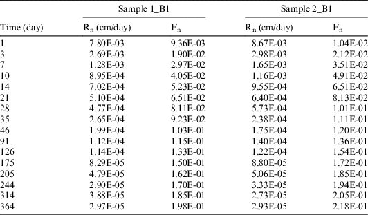
The values of 14C measured in the leachate solution at each sampling times were used to compute the 14C cumulative release fraction (Fn) and leaching rate (Rn). The measured 14C activity in the leachate solution was corrected for the dilution factor due to the leachate sampling/renewal and divided by the initial 14C activity in the irradiated graphite subject of the leaching test to get the cumulative release fraction. The results, both for the cumulative release fraction and for the leaching rate, are reported in Table 5.
Table 5 14C cumulative release fraction (Fn) and leaching rate (Rn) for the aerobic leaching tests.

The results obtained by the two parallel are very similar (see Figure 2, comparing respective tests on the B1 sample), confirming the reproducibility of the leaching tests.

Figure 2 Evolution of the 14C cumulative release fraction and leaching rate.
The results of the aerobic leaching tests confirm a very low release rate of the 14C. After 376 days of immersion in alkaline solution, around 1.33 × 10³ Bq of 14C was released as dissolved species, representing 1.75% of the initial 14C activity of the irradiated graphite subject of the leaching test.
The leaching rate is higher in the first days of immersion and it decreases after that, indicating a two stage process: an initial quick release with an average release rate of 5.48 × 10⁻² % of the inventory/dayFootnote * during the first 48 days, followed by a slower release of around 4.62 × 10⁻³ % of the inventory/day. These two stages of 14C release could be associated with the initial release of the more labile species arising from the 14N impurities or from the 13C from different depositions, while the second stage is most probably linked to 14C created in the matrix (Carlsson et al. Reference Carlsson, Kotiluoto, Vilkamo, Kekki, Auterinen and Rasilainen2014).
The acid stripping/wet oxidation tests carried out on the leachate solutions show that in all solutions more inorganic than organic 14C was released. The ratio between inorganic and organic 14C release during the leaching test is almost constant during the test. The inorganic fraction of 14C measured in the leachant solution sampled at different leaching intervals ranges between 66% and 70% of the total 14C released as dissolved species, with an average of 67.89% and a standard deviation of 1.84%. The organic 14C on leachant solution sampled at different leaching intervals is ranging between 30% and 34% of the total 14C released as dissolved species, with an average of 32.11%.
14C Release in Alkaline Solution under Anaerobic Conditions
The experimental conditions for anaerobic leaching tests were similar with those described in the aerobic leaching tests, except for the volume of the leachate solution was increased due to the larger diameter of the irradiated graphite available for these anaerobic leaching tests (Table 6).
Table 6 Tests parameters for anaerobic leaching.

The volume of leachate solution sampled/renewed at each testing time was 50 mL. The values of 14C measured in the sampled solutions at each sampling times were used to compute the 14C cumulative release fraction (Fn) and leaching rate (Rn). The results are reported in Table 7.
Table 7 14C cumulative release fraction (Fn) and leaching rate (Rn) for the anaerobic leaching tests.
Similar to the aerobic leaching tests, the experimental results indicate a good reproducibility of the tests (Figure 3, comparing respective tests on the B2 sample).

Figure 3 Evolution of the 14C cumulative release fraction (left) and leaching rate (right).
The results of the anaerobic leaching tests also show a low 14C release. After 364 days of testing, less than 450 Bq of 14C was released as dissolved species, representing 1.85% of the initial 14C activity of the irradiated graphite subject to the leaching test.
As also observed in the tests carried out in aerobic conditions, the leaching rate is high in the first days of immersion. The initial quick release takes place with an average rate of 9 × 10⁻² % of inventory/day during the first 48 days while the slower release has a rate of around 4 × 10⁻³ % of inventory/day.
The acid stripping/wet oxidation tests carried out on the leachate solutions sampled at different leaching intervals show that under anaerobic conditions, more organic than inorganic 14C was released, with an almost constant ratio between organic and inorganic 14C. The organic fraction of 14C released as dissolved species under anaerobic conditions was measured in the leachant solution sampled at different leaching intervals ranges between 61% and 66%, with an average of 64.57% (and a standard deviation of 3.08%).
CONCLUSION
The results of the leaching tests confirm the very low release rate of the 14C. At the end of the leaching tests (376 days), around 1.33E3 Bq of 14C in aerobic conditions and 450 Bq in anaerobic condition was released as dissolved species, representing 1.75% and 1.85% respectively of the initial 14C activity of the irradiated graphite subject of the leaching test.
Both for anaerobic and aerobic conditions, the leaching rates are high in the first days of immersion and decrease after that, indicating a two stage process: an initial quick release (less than 9 × 10⁻² % of the inventory/day is released for the first 48 days) followed by a slower release rate (around 4 × 10⁻³ % of the inventory/day).
The performed leaching tests show that the total 14C released in solution is similar both for aerobic and anaerobic conditions. Under anaerobic conditions, 14C is released predominantly as organic species, with an average fraction of organic 14C of around 65% of the total 14C released, while under aerobic conditions, more inorganic than organic 14C is released in solution, with an average fraction of inorganic 14C of around 68% of the total 14C released. This behavior is due to the redox sensitivity of 14C and consequently the released species on the water-graphite interface is dependent on the ambient atmosphere. The results obtained from an experiment performed on Oldbury Magnox graphite, at ambient temperature, under aerobic and anaerobic atmosphere (Baston et al. Reference Baston, Preston, Otlet, Walker, Clacher, Kircham and Swift2014), show that under anaerobe conditions and ambient temperature, 14C released as gaseous phase was predominantly in the form of hydrocarbons and other volatile organic compounds and CO, with a ratio of 14C in hydrocarbons/organic compounds to CO of 2:1. In experiments performed on the same i-graphite but under aerobic conditions, the total 14C gaseous release rate was similar to the one released under anaerobic conditions, but the ratio of organic.
ACKNOWLEDGMENTS
The results presented in this paper were achieved in the frame of CArbon-14 Source Term project funded by the European Union’s European Atomic Energy Community’s (EURATOM) Seventh Framework Programme FP7/2007-2013 under grant agreement no. 604779, the CAST project.


 Open access