1.0 BACKGROUND
Over 60 years of activities in space have produced great benefits for the world population, from the SatNavs in our cars, to satellite communications/broadcasting, as well as weather forecasting, environment monitoring, and the list could go on. There are literally hundreds of devices for everyday use and applications that rely on satellite technologies. When the satellites that deliver these services reach the end of their life and stop working, they are normally left in-orbit. In 2018 there were almost 3,000 dead satellites still in-orbit, not to mention the final stages of the rockets that were used to put satellites into orbit, as well as fairings and other hardware. In addition to intact objects there are also millions of fragments that have been produced by the degradation of these bodies from flakes of protective materials to shrapnel produced by explosions and collisions(Reference Bonnal and McKnight1). Altogether, a mass of over 8,000 tons of debris is currently orbiting the planet, posing as a threat for operative satellites.
We have not yet triggered the nightmare scenario known as the Kessler syndrome (named after the scientist who first investigated this phenomenon(Reference Kessler and Cour-Palais2)), which is when fragments formed by a collision hit other objects producing explosions creating new fragments that will hit other objects. This would result in a cascade effect that grows exponentially and would rapidly increase the density of objects to the point of making particular orbits unusable. Furthermore, we cannot be complacent and simply continue to put more satellites in-orbit ignoring this problem, as collisions with space debris have already occurred (see for example(Reference Wang3)). Almost routinely, the ISS and other satellites have to perform maneuvers to avoid being hit by other orbiting objects. There are guidelines to try to mitigate the growth of the debris population(4)— these have been produced by the Inter-Agency Space Debris Coordination Committee (IADC), which is an international forum of governmental bodies (e.g. national space agencies), for the coordination of activities related to the issues of man-made and natural debris in space. Some agencies and government bodies have adopted these guidelines and complemented them with further regulations. Perhaps the most quoted guideline is that satellites should be de-orbited, or re-orbited (putting them in a graveyard orbit) within 25 years from their launch. However, although these guidelines have been in place for some time, they are just “guidelines” and not enforceable regulations. Various countries, for example, have tested ground-launched anti-satellite missiles, hitting their satellite target in-orbit producing step increases in the space debris population. Hence, for a variety of reasons, from political to technological, to constrain the growth of the space debris population has proven to be challenging. There is consensus among the experts in the field that to stabilise the debris population, in view of the growing number of launches, the active removal of some debris from some of the most utilised orbits is necessary(5,Reference Liou and Johnson6) , although the quantification of the benefits strongly depends on the modelling assumptions(Reference White and Lewis7).
Various researchers and organisations have investigated the field of Active Debris Removal (ADR)(Reference White and Lewis8,Reference Bonnal, Ruault and Desjean9) and various methods have been proposed to address this issue(Reference Shan, Guo and Gill10,Reference White and Lewis11) .
The European space agency has probably been the most active international participant in the space sector that is addressing this issue with its Clean Space Initiative(Reference Innocenti12,13) . This is articulated in the area of EcoDesign (embedding environmental sustainability within space mission design), CleanSat (developing technologies to prevent the creation of future debris) and in-orbit servicing/ADR (removing spacecraft from orbit and demonstrating in-orbit servicing of spacecraft) to embrace all the relevant domains. The French space agency (CNES), has also been very active and has funded studies including OTV that takes into account different ADR mission scenarios(Reference Pisseloup, Salmon, Cougnet and Richard14). Similarly the UK space agency has funded studies and issued guidelines applicable to UK crafts. The German space agency (DLR)’s DEOS (Deutsche Orbital Servicing Mission) aimed to progress towards ADR, designing a system for rendezvous with a non-cooperative and tumbling spacecraft by using a robotic manipulator system incorporated within a servicing satellite(Reference Reintsema, Sommer, Wolf, Theater, Radthke, Naumann, Rank and Sommer15).
In the industrial sector, Airbus focused on the capture technologies including a robotic arm, a net(16), and harpoon demonstrators(Reference Pisseloup, Estable, Pegg, Ferreira, Delage, Pairot, Salmon, Ratcliffe and Frezet17) as more cost effective capture technologies. Aviospace has also recently participated in some ADR studies such as their capture and de-orbiting technologies (CADET) studies(Reference Chiesa, Gambacciani, Renzoni and Bombaci18) as well as the Heavy Active Debris Removal (HADR)(Reference Bicocca19). The company D-Orbit has proposed solid rocket de-orbitation for the S-SAT mission(Reference Antonetti20) and other methods have been proposed, e.g. ion-beam shepherd, Gecko adhesives, and polyurethane foam(Reference Merino, Ahedo, Bombardelli, Urrutxua, Pelaez and Summerer21-Reference Trentlage and Stoll23), just to name some of the most relevant proposals. A very popular de-orbiting system has been dragsails, which attracted significant research attention and has already produced working devices(Reference Hobbs, Kingston, Roberts, Juanes, Sewell, Snapir, Robinson, Llop, Hobbs and Patel24-Reference Underwood, Denis, Viquerat, Taylor, Sanders, Stewart, Massimiani, Bridges, Masutti, Aglietti, Schenk, Duke and Fellowes26).
It is acknowledged that for any new proposed space technology, in-orbit demonstration is a significant stepping stone to de-risk the final implementation. The RemoveDEBRIS mission discussed in this article and other publications(Reference Forshaw, Aglietti, Navarathinam, Kadhem, Salmon, Pisseloup, Joffre, Chabot, Retat, Axthelm, Barraclough, Ratcliffe, Bernal, Chaumette, Pollini and Steyn27-Reference Forshaw, Aglietti, Salmon, Retat, Hall, Chabot, Pisseloup, Tye, Bernal, Chaumette, Pollini and Steyn30) has been the first mission to perform successfully in-orbit demonstrations of a series of technologies for ADR thus de-risking their future industrial implementation.
2.0 MISSION OVERVIEW
The purpose of the mission was to perform in-orbit demonstrations of technologies for the active removal of large space debris. These are typically old satellites which were no longer working upper rocket stages and large fairings. More specifically, the technologies that were tested were: two technologies (a net and a harpoon) for the capture of the debris; a technology for the observation of a debris (a LiDAR cameraand software) in order to automatically determine parameters such as distance, spinning rates, etc., which would be essential during the rendezvous and debris capture; and finally a technology for the de-orbiting at the end of life, the dragsail.
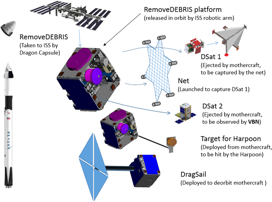
Figure 1. Infographic of the RmoveDebris mission.
The need to perform in-orbit demonstrations stems from the impossibility to perform fully representative tests on the ground and the need to increase TRL of the devices, reducing development risks before embarking in a real industrial ADR mission.
As seen in Fig. 1, the satellite was put into orbit in two stages. It was taken to the International Space Station during one of the Space X periodic resupply missions;d then from the ISS, using the airlock in the Japanese module, the satellite was transferred outside the ISS and released in-orbit by the ISS robotic arm.
The actual RemoveDebirs mission was then performed, and in terms of hardware this consisted of a mini satellite platform (mothercraft) of approximately 100kg mass that hosted the payloads performing the demonstrations. Once in-orbit, the platform released two 2U CubeSats that acted as space debris, targets for the net capture and VBN technology demonstration. The harpoon functioning was demonstrated by firing the harpoon from the mothercraft at a target (the size of a table tennis bat), which was held at the end of a deployable boom at a distance of about 1.5 metres from the platform.
Finally, the dragsail was supposed to be deployed from the mothercraft. This consisted of an inflatable 1m-long mast supporting a mechanism that deploys radially four booms, that extending, unfurl four quadrants of sail. Once fully deployed, the sails form a square of approximately 3 × 3 metres, with the deployable booms as diagonals. The inflatable mast holds the assembly from the centre, at 1 metre distance from the mothercraft (see Fig. 1). As the craft is in a low earth orbit, the residual atmosphere allows the sail to produce drag that slows down the satellite, significantly accelerating the de-orbiting process.
2.1 Mission team
The mission design was started in 2014 and was performed by the team described in Table 1, led by the Surrey Space Centre at the University of Surrey. The overall cost of the mission was approximately 15M euros. This was supported by a grant from the European Commission, part of its Framework Severn research funding round, and provided a 7M euro contribution to the cost of the project, with the remainder self-sponsored by the partners.
Table 1 RemoveDebris Mission Team

2.2 Launch and Early Orbit phase
At the end of the assembly integration and testing activities, carried out in the SSTL cleanroom in Guildford, UK, the satellite, appropriately packaged (with protective panels, in a foam clamshell that was contained in a box, which was finally put in the transportation case) was shipped to Cape Canaveral for launch. Once at the launch site, the external transportation/casing was removed, leaving the craft with its protective panels in the protective foam clamshell. In this configuration, the craft was put in the cargo transfer bag and finally into the Dragon capsule.
The launch on the 2 April 2018 was nominal, with the Dragon capsule propelled into orbit by the SpaceX Falcon 9 Rocket, and the craft arrived at the ISS two days later as planned. The craft was then kept stored until mid-June, waiting for its scheduled time slot for unpacking and deployment into orbit. The unpacking consisted of removing the foam shell casing and protective panels, and the craft then was mounted on the sliding table in the Japanese module airlock. No other servicing operations were required form the ISS crew to make the craft operational. Once on the external side of the airlock, the craft was handled by the ISS robotic arm equipped with the NanoRacks Kaber Microsat Deployer, and released in orbit on the June 20, 2018. Figure 2 shows the craft a few minutes after its release from the ISS.
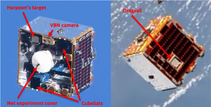
Figure 2. RemoveDebris in flight, pictures taken from ISS.
The craft was released completely switched off in compliance with the ISS safety requirement, and contact was made during the first pass after power up, over the SSTL ground station in Guildford, UK.
The telemetry showed that the spacecraft was performing nominally, e.g., battery was fully charged and temperatures as expected, and commissioning progressed with switching on the spacecraft on-board computer. Next, the craft was de-tumbled from the slow initial angular rate and brought to a controlled attitude state. Attitude and orbital control system commissioning progressed until the platform was in a coarse Nadir pointing mode.
All other platform checks to verify health and functioning of the key modules not already checked were successfully performed.
The spacecraft then performed a series of maneuvers to verify its performance against the requirements for the various demonstrations.
The final phase was the calibration and characterisation of the cameras and VBN were tested over a range of exposures and frame rates which were planned for use on the experimental demonstrations and related parameters were adjusted.
By mid-September, the craft was ready to start the demonstrations with the net capture scheduled as the first experiment. This was to be followed by the VBN demonstration, harpoon firing and finally de-orbit sail deployment, with the series of experiments planning to take approximately six months.

Figure 3. Debrisat 1 (a) stowed configuration (b) deployed configuration.
3.0 NET CAPTURE TECHNOLOGY DEVELOPMENT AND DEMONSTRATION
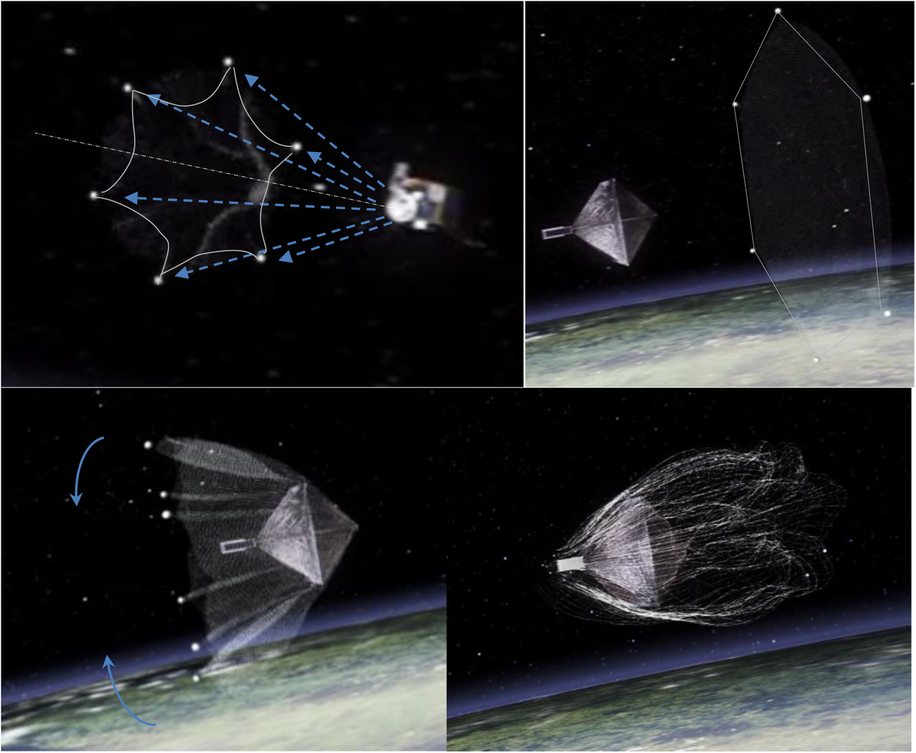
The first demonstration planned, was the net capture. For this demonstration, the first CubeSat had to be released form the mothercraft, and while this slowly drifted away (planned separation speed 5cm/sec) and reached an appropriate distance (approx. 7m), the net had to be launched from the mothercraft to capture the CubeSat. After the CubeSat release from the mothercraft, and before this is captured by the net, the CubeSat deploys some inflatable structures to increase its original size (from the 10 × 10 × 20cm dimension of a 2U CubeSat, to approximately 1m side length pyramid structure (see Fig. 3)). This is in order to be more representative of the size of a larger space debris and produce a situation more representative of the net capture dynamics. The net is held in a container/canister (see Fig. 4) and is deployed by launching six masses simultaneously that are attached along the perimeter of the net. The masses are cylindrical, with a push-off spring at the base, and contained in six barrels located on the internal wall of the canister (see Fig. 4). A lid closes the canister pushing the masses down their barrels, compressing their push-off spring. Once the lid of the canister is ejected, the masses are pushed out by their springs along trajectories that funnel out from thelongitudinal axes of the canister in order to drag the net out from the central volume of the container, progressively stretching it open (see Fig. 5). During its deployment, initially the net will take the shape of a six-pointed star with each of the masses pulling one of the vertices of the “star,” and eventually when fully deployed, the perimeter of the net should take approximately a hexagonal shape with vertices on a 5m dimeter circle. Once the target has been captured, the masses are naturally pulled towards the longitudinal axis by the net, and each of the masses draws a string that runs along the perimeter of the net in order to close it, like a drawstring bag. The closure of the net is performed to ensure the retention of the target, as otherwise, after the initial capture, the net might open up and release the target. The activation of the drawstring is commanded by a timer, and the whole demonstration was planned to be filmed by two supervision cameras, starting recording just before the release of the target CubeSat.

Figure 4. Net capture device (a) CAD model of the container, (b) hardware, container with masses partially inserted in the barrel and lid resting on the masses (c) container closed and ready for vibration testing.

Figure 5. Sequence from video animation of the net ejection and DSAT#1 capture.
The design of the hardware has been supported by extensive experimental test campaigns, as both, the target CubeSat and the net launching device, have complex dynamics. For example, the CubeSat presents the challenge of the inflatable booms that deploy the sail quadrants, and whose inflation/deployment is almost chaotic, and similarly the deployment of the net, from tightly packed in the container to fully open is difficult to model mathematically with good reliability. Even the CubeSat deployer required significant testing to verify the very low ejection speed that was required.
3.1 Hardware ground testing
The functioning of the net device was verified during ground test of increasing complexity. From simple packing and unpacking tests with people pulling the corners of the net out of the container to make sure that there were no snags during deployment, to functional tests in zero-g and vacuum in the drop tower (these tests only allowed us to verify the first second of the net deployment process), to tests during parabolic flights, to verify the closure of the net. Although these tests could give confidence in particular aspects of the design, none of the tests could verify the whole capture of a free-floating non-cooperative target in space, with hardware that was similar to what would be required to capture a real piece of large space debris. Hence, the in-orbit demonstration was necessary to give full confidence in the design, and reduce the risk of the further scaling up that will be necessary to utilise this technology in real ADR missions to capture an object a few metres in size.
Concerning the target CubeSat, a significant test campaign was carried out to consolidate its design. From the initial baseline that included a six-boom deployable structure as shown in Fig. 6, which gave substantial challenges in terms of its capability to withstand a harsh vibration environment, the design evolved into a five-boom configuration visible in Fig. 3. The inflation is driven by two cool gas generators — however, during most of the testing activities and to allow several repetitions and limit cost, compressed air was used.
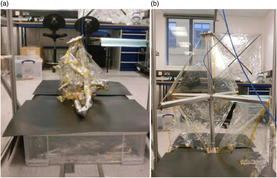
Figure 6. 6-DSat inflation testes, six-boom configuration (a) during inflation (b) fully inflated.
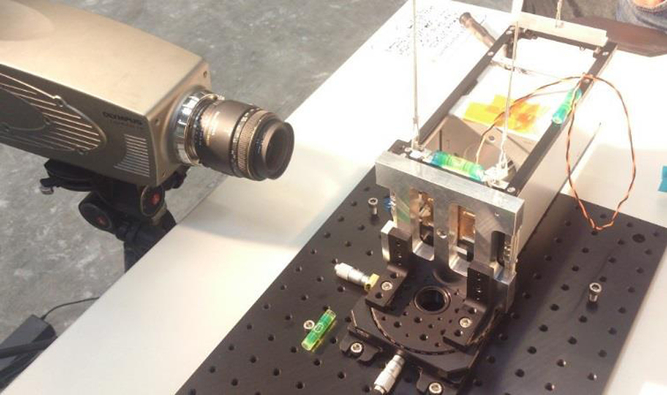
The main challenge for the CubeSat deployer used to eject the CubeSats from the platform was to achieve a very low ejection speed, as in a realistic scenario there would be a very low relative speed between a debris and the spacecraft that is capturing it. This was achieved by implementing a two-stage deployer system illustrated in Fig. 7. The first stage pushes the CubeSat out of its container using a typical large compression spring system that, at the end of its run, keeps the push plate flush at the opening of the container with the base of the CubeSat retained by the push plate. The second stage is the CubeSat release system. This separates the CubeSats and gently pushes it away using low stiffness springs. The performance of this mechanism was verified in the lab using a long pendulum system for gravity compensation and a high-speed camera to measure the release speed of the CubeSat (see Fig. 8).
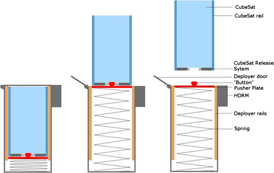
Figure 7. Schematic of the CubeSat Ejection system.

Figure 8. Deployer and CRS: Detail of the velocity testing setup. 2U CubeSat suspended on pendulum and high speed camera.
3.2 In-orbit demonstration
The in-orbit demonstration (September 16, 2018) was filmed by the two supervision cameras on the platform as planned. In addition, it was decided to use this opportunity to test also the functioning of the VBN cameras (i.e., a digital camera and a LiDAR system that will be further discussed in the next section), and therefore the demonstration was filmed by a total of four cameras. The type of imagery is visible in Fig. 9.
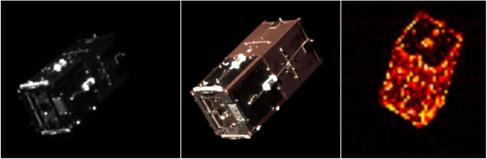
Figure 9. Standard supervision camera, VBN digital camera, VBN LiDAR camera.
Figure 10. DSAT#1 with lateral inflatable booms deployed.
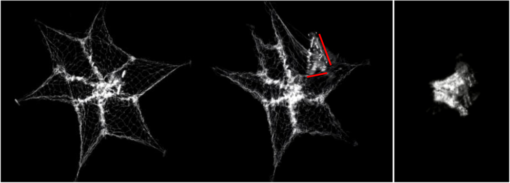
Figure 11. Left — before the capture, two lateral booms visible. Centre — Moment of the Net capture of DSAT#1, one of the satellite sails is shown, between the lateral and longitudinal booms — Right – after the capture, DSAT#1 tangled in the net.
From the imagery it is possible to see the CubeSat drifting away from the mothercraft at a velocity slightly higher than planned (approximately 7.5cm/sec) and then inflating two of the four inflatable booms making the base of the pyramid (see Figs. 3 and 10). The inflation of the longitudinal boom is also visible, as the net captures the CubeSat (see Fig. 11).
As the booms inflated, the CubeSat started spinning, and this was most likely due to a gas leak from the two booms not correctly inflating, acting as a thruster, and generating a moment to the CubeSat. As the net was travelling towards its target (Fig. 5), pulled by the six throw masses, it assumed the shape of a six-point star (each point pulled by one of the masses). However, the central area of the net remained slightly tangled together preventing a full stretch of the mesh. It is estimated that the net opened to approximately 4m diameter and then hit the spinning target wrapping itself around it. The capture itself happened at a distance of approximately 11m, and the distance was estimated from the knowledge of the camera field of view and the size of the target. As the net wrapped itself around the target, the imagery did not allow us to determine whether the drawstring mechanism worked properly. Although it was clear that the net achieved its main purpose (i.e., to capture the target). From the way it tangled itself around the CubeSat and its deployable structures, it is very unlikely that later on the CubeSat could unwrap itself and escape from the net. All the telemetry (two-line elements), from the moment of the capture to the complete de-orbiting of the CubeSat (March 2, 2019) enveloped by the net, is consistent with a single object.
In a real operational scenario the net would be tethered to the mothercraft, so that after the capture of a debris the mothercraft can tow it down and de-orbit together. However, this would require the mothercraft to have a very capable propulsion system and sophisticated AOCS that would significantly impact the mission budget, and this was considered to be beyond the scope of this demonstration.
Besides propulsion, to deploy this technology on an industrial scale to capture real large space debris, the technology will need scaling up, but there is nothing in the current design that could prevent an increase in size to enable capture of debris that could have dimensions of a few metres.
4.0 VISION BASED NAVIGATION
The second demonstration t tested the performance of two cameras for VBN and related software. The two cameras were a standard high-quality digital camera and a flash imaging LiDAR system, whereby the target is illuminated by flashes of laser and reflections are captured by a sensor, enabling the measurement of the distance of the target.
The purpose of this demonstration was to test the hardware and to assess the state-of-the-art of image processing (IP) and navigation algorithms based on real flight data.
The device is shown in Fig. 12, together with the CubeSat that was released by the mothercraft in order to be observed by the two cameras. The imagery from the cameras enables the reconstruction of the object and its dynamics (shape, distance, and spinning rate) that can be used for rendezvous algorithms for relative navigation.
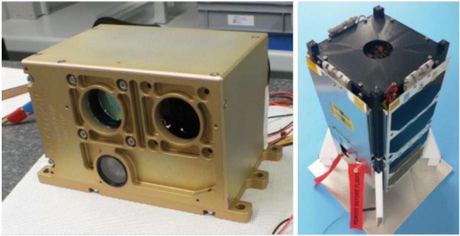
Figure 12. Left: Vision-based navigation payload, Right: DS-2 target in deployed state.
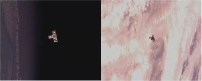
Figure 13. DSAT#2 with different backgrounds.
4.1 In-orbit demonstration
The CubeSat target for the VBN was released by the mothercraft on the October 28, 2018 and pushed away with a velocity of 2cm/sec. It was released by the same type of separation mechanism as that was used for the first CubeSat but with lower push-off spring energy.
One of the challenges addressed by this experiment, was to recognise the target independently from the background (see Fig. 13), and this demonstration provided a wealth of real data to assess the performances and robustness of the VBN algorithms. If a model of the geometry of the object being observed is available (e.g. a CAD model), the software can combine it with the sensor’s measurements and improve the overall estimation of the kinematic of the object and its visualisation (see Fig. 14). If other physical data of the target is available (i.e. inertia matrix), the estimation can be further improved including the equation governing the dynamics of the object in the algorithm.
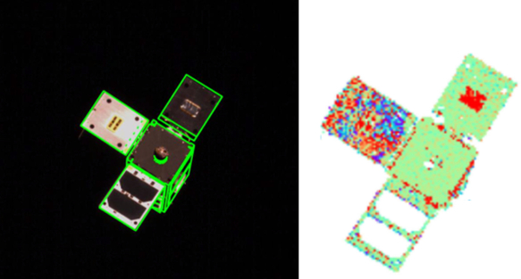
Figure 14. Left: View of DSAT#2 with shape contours, Right: image from LiDAR camera.
In our experiment, the measurements obtained by the LiDAR system (target distance and spinning rates) were compared with the information obtained by the GPS on board the CubeSat, which were transmitted to the mothercraft via an inter satellite link.
Figure 15 shows a comparison of the measurements of the relative distance between mothercraft and CubeSat, using raw data from the various sensors while the target was tumbling and also the background was changing, therefore varying the level of noise during the experiment. As knowledge of the physical characteristics of the target can improve significantly the estimation, further work in this direction is currently being carried out.
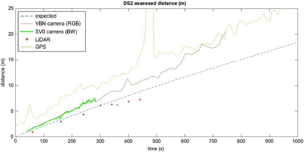
Figure 15. Comparison of distance measurements using different systems.
Downloading all the data from the experiment took a few weeks, as the videos were very large files and contact to download the data could only be made for a few minutes every day when the satellite was passing in view of the ground station in Guildford.
5.0 HARPOON
The next experiment to be performed was the harpoon capture, and this was executed February 8, 2019. The demonstration starts activating the frangibolt that retained the target pressed against the mating structure of the chassis harpoon target assembly(Reference Aglietti, Forshaw, Viquerat and Taylor31) (see Fig. 16). After the target has been freed, the deployable boom that supports it starts to uncoil/deploy moving the target to a position 1.5 metres away, in front of the harpoon firing device.
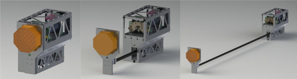
Figure 16. Harpoon target assembly. Left — stowed configuration, the target is held against the chassis of the device by a frangiblot. Centre — Once free, the target is moved into position by the deployable boom. Right — device fully deployed with target in its final position.
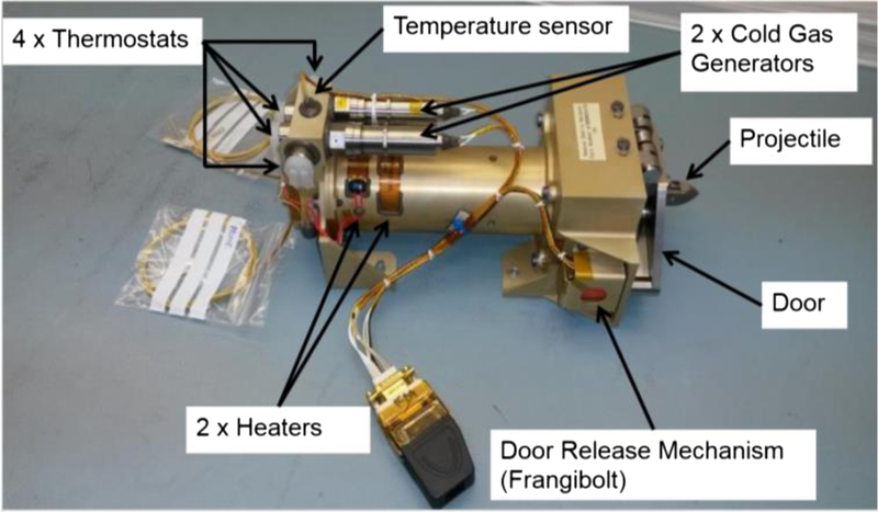
Figure 17. Harpoon firing device.
The deployment of the target is recorded on video by the mothercraft supervision camera. Once the video has been downloaded and reviewed to confirm that the target is correctly deployed, the harpoon can be fired. Before firing the harpoon its safety door, kept closed by two frangibolts, has to be opened to free the harpoon/bullet. The harpoon is launched using compressed gas produced by two cool gas generators, and it is tethered to the mothercraft using a line whose length is significantly longer than the harpoon distance (see Figs. 17 and 18). A total of 27 harpoon firing tests were conducted to verify various aspects of the design and in particular the behavior and strength of the tether system, as it was mandatory to demonstrate the capability to retain the harpoon under any conditions (including missing the target). Early in the program, considerable attention was also given to the design of the tip of the harpoon and the barbs, with various design iterations, shown in Fig. 19, to improve its capability to imbed itself and lock on the target.

Figure 18. Harpoon firing device, projectile and tether.
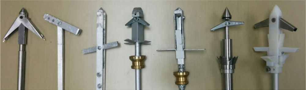
Figure 19. Harpoon tip and barbs design iteration.
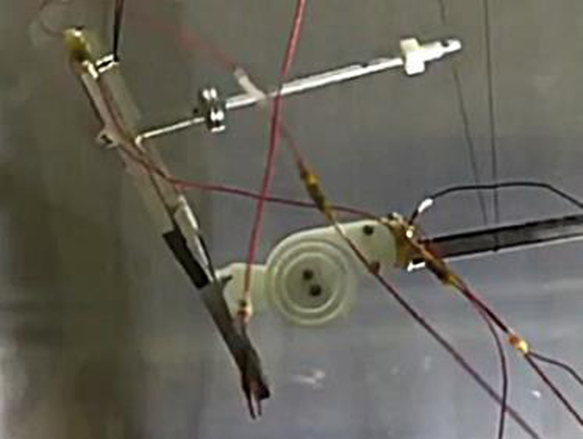
Figure 20. Harpoon target support implementing “shock absorber.”
The target, roughly the size of a table-tennis bat, includes an aluminum honeycomb panel of contraction representative of an old satellite structure that has to be struck by the harpoon.
The deployable boom that supports the target is a lightweight CFRP with a U cross section and a series of holes along its length that engage a gear used for the deployment the boom.
During ground testing it became apparent that the high energy of shock of the harpoon hitting the target was sufficient to snap the target off the boom. Consideration was given to include a system, similar to a clock spring to (Fig. 20) reduce the amplitude of the mechanical shock upon the harpoon impact, and related stress on the structure. However, as after the impact the harpoon would effectively retain the target, the possibility of the target breaking off the boom was not deemed a particular concern and therefore the shock absorber was not implemented in the flight model.
5.1 Harpoon in-orbit demonstration
After the boom was deployed, the imagery was downloaded and examined to verify the status of the system before proceeding with the demonstration. This showed a significant oscillation of the target (see Fig. 21) with rotations of up to +/−17deg and translations of the target central area of a few centimetres. This was because the target was supported in a cantilevered configuration by a boom with relatively low stiffness and damping. Excited by the microvibrations generated by the equipment on board the platform, the system resonated, producing large oscillations of the target. As the main source of the platform microvibration were the actuators of the attitude control system, the issue was resolved performing the experiment in a mode of operation where the actions of the attitude control system had been minimised.
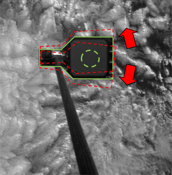
Figure 21. Target deployed at the end of the boom, in green the nominal position and in red the positions at the extreme of the oscillations whose direction is indicated by the red arrows.
In this new mode of operation, it was verified that the target was stable, and it was possible to fire the harpoon. As visible in Fig. 22, the dart hit the target in the centre and due to the mechanical shock the target snapped off the boom (Fig. 23), and floated away tethered to the mothercraft via the harpoon tether. After some time floating around the platform, the target retained by the harpoon tether wrapped itself around the boom (Fig. 24).
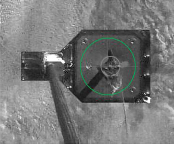
Figure 22. Harpoon imbedded in the target.

Figure 23. Target snapping off the end of the boom.

Figure 24. Target retained by harpoon tether wrapped around the boom.
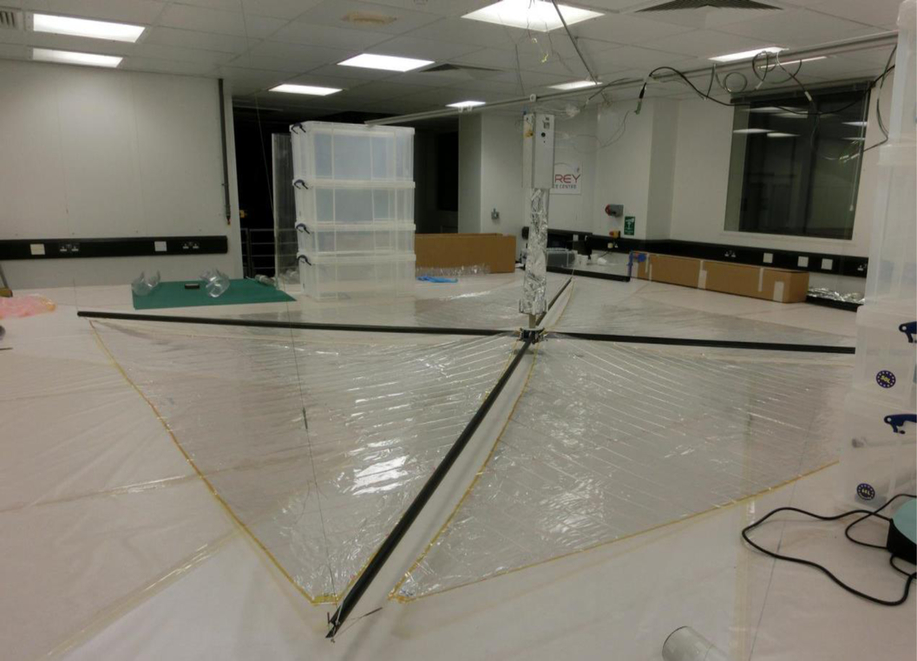
Figure 25. Dragsail system.
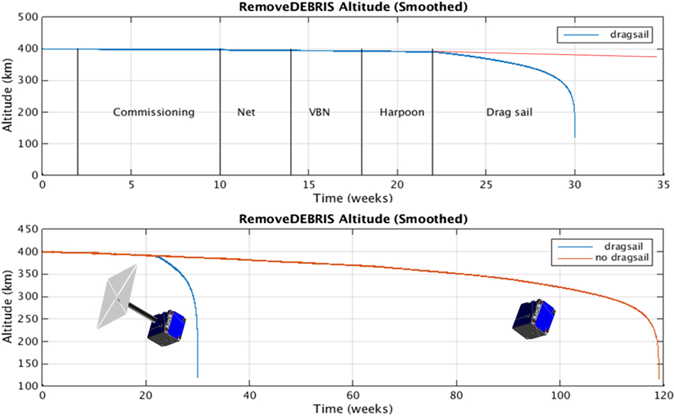
Figure 26. RemoveDebris de-orbiting performance prediction with and without dragsail.
6.0 DRAGSAIL AND DE-ORBITING
The final phase of the mission consisted of an accelerated de-orbiting of the craft, triggered by the deployment of a drag-sail. The concept of operation of this device is that deploying a sail like that shown in Fig. 25 in low earth orbit, where there is still some residual atmosphere, increases the drag, reducing the velocity of the satellite, so it de-orbits more quickly. The graphs in Fig. 26 show the improvement in the de-orbiting time which can be produced by this kind of system. In this case, the prediction showed that deploying the sail could have reduced the de-orbiting time to approximately 10% of its natural de-orbiting time.
The initial configuration of the craft had all the experiments mounted on the same side of the satellite in order to be monitored by the surveillance cameras. However, as the dragsail was the last device to be operated, possible malfunctions of the previous experiments, (e.g. incapability to retract the boom supporting the harpoon target after its demonstration) would have impeded its deployment. In one of the last design iterations, to avoid any possible interference with the previous demonstrations, it was therefore decided to mount the dragsail on the opposite side of the satellite (see Fig. 2). Unfortunately, this did not allow us to video the operation of the dragsail, and successful deployment would have been confirmed mainly by the more rapid de-orbiting of the craft. Other indicators, such as changes/reduction in power generated by the solar panels due to shadowing of the sails, changes in telemetry from the sun sensor, and observation from the ground (significant increase in brightness of the object) would have confirmed the successful deployment.
A command to deploy the dragsail was given March 4, 2019. In the following days, some changes in the brightness of the object were reported, but we could not detect significant changes in the de-orbiting trajectory or in any of the other indicators. Figure 27 shows the altitude of the mothercraft, which is naturally de-orbiting (expected time for complete de-orbit is approximately 2.5 years), but no significant change occurred from March 4. Note that the first CubeSat, wrapped in the net, de-orbited in less than six months and the second CubeSat is also de-orbiting at a faster rate than the mothercraft.
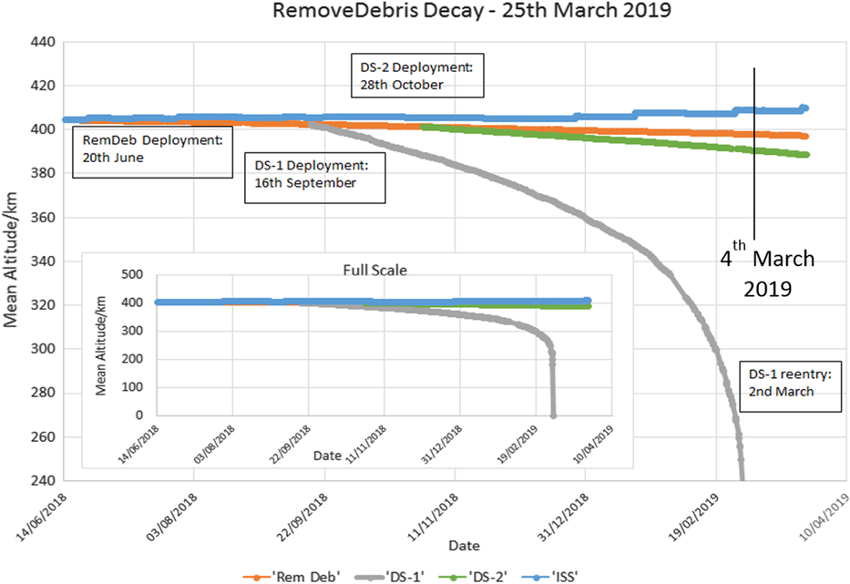
Figure 27. Decay of the various RemoveDEBRIS objects.
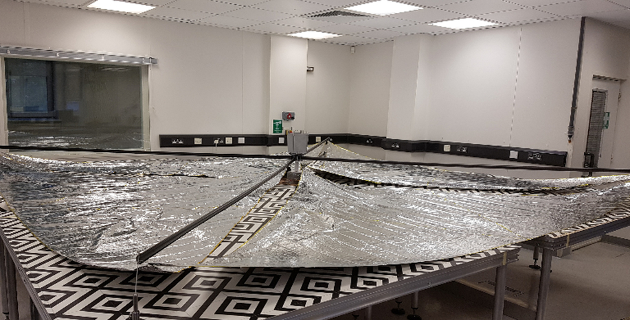
Figure 28. Ground testing of the dragsail for the SSO-A mission.
At this stage it has not been possible to confirm the nature of the anomaly in the operation of the dragsail, although most of the data is consistent with an issue with the deployment of the inflatable mast that supported the sails. However, the lesson learned in the development of the RemoveDebris drag-sail has been put into practice in the development of two new dragsails that have been supplied to the space flight industries for their the SSO-A mission, and all the telemetry available for that mission has confirmed a successful deployment.
As the purpose of the RemoveDebris demonstrations was to pave the way to industrial exploitation of the various technologies that were tested, the dragsail experiment also fulfilled its purpose.
7.0 CONCLUSIONS
The RemoveDebris mission has been the first successful in-orbit demonstration of a series of technologies for ADR.
Both the net and harpoon have been proven viable methods to capture large space debris. Indeed these devices will need scaling up, possibly up to one order of magnitude in terms of the size of the hardware, in order to be used in a real industrial scenario, for example to capture large defunct satellites. However none of the technologies implemented in the systems have features that would prevent their increase in size.
The VBN demonstration, besides verifying the functioning of the hardware and software, collected a wealth of data that will be useful for years to come.
The development of the dragsail and the anomaly in its operation, although disappointing at the time, has provided important lessons that have enabled the successful manufacturing and operation of a new generation of drag-sails. Most importantly the use of inflatable structures in space still poses significant challenges, and alternative solutions seem to deliver higher reliability. In our case, also the need for extensive testing, implementing a higher level of quality control in the whole MAIT process has certainly contributed to achieving success in the new generation of drag-sails.
Once again, this project reconfirmed that the systems that underwent extensive ground testing performed better than those that relied on a small number of tests.
Overall, from a programmatic perspective, one important lesson learned was that in case of launches via the ISS, an earlier engagement with the ISS safety review process is very beneficial. In fact in comparison to standard launches, where the craft is put directly in orbit, transiting through the ISS requires a higher level of safety. This is relatively easy to implement directly in the design if this is done at an early stage, rather than having to add modifications or carry out further unscheduled test activities to achieve compliance.
Still, from a programmatic perspective, another peculiarity of the project was the “loose” contractual control of the interfaces between partners. This derived from the fact that the whole project was set up as a research collaboration between members of a consortium led by the SSC (the consortium coordinator), and with responsibilities described at top level in a research proposal subsequent description of work. Such consortium configuration was rather different from the typical contractual arrangement used to deliver space missions (e.g. a satellite development would normally be led by a prime contractor which leads a group of Subcontractors with responsibilities that are specified in detail in their subcontracts). Whilst on one hand this enabled flexibility in the interfaces to optimise, from a technical perspective, the interface and distribution of the work, it created some challenges from a project management perspective. The key for the successful delivery of this kind of project was to maintain top level alignments of the overall objectives and the partners’ willingness to absorb some extra (unscheduled) work deriving from adjustments of the interfaces.
Besides its technical success, this project attracted significant media attention, which was welcome, as it raised the awareness of the issue of the space debris in the general public.
ACKNOWLEDGEMENTS
This research was supported by the European Commission FP7-SPACE-2013-1 (project 607099) ‘RemoveDebris — A Low Cost Active Debris Removal Demonstration Mission’, a consortium partnership project consisting of: Surrey Space Centre (University of Surrey), SSTL, Airbus GmbH, Airbus SAS, Airbus Ltd, Ariane Group, Innovative Solutions in Space (ISIS), CSEM, Inria, Stellenbosch University.
The authors would also like to acknowledge the help and support of the launching agent NanoRacks as this has been crucial to successfully deliver this mission.