


1. Introduction
Technological advancements in unmanned aerial vehicles (UAVs) have led to the growth of industries developing solutions for various civilian and military applications. UAVs are extensively used for various applications like aerial photography, package delivery, mapping of difficult terrain or environments, reforestation, visual inspection, search and rescue operations [Reference Waharte and Trigoni1]. Drone delivery networks like Amazon Prime Air [2], UAV-based medical transportation like Zipline [3], drone photography with DJI [4], Skydio [5] are platforms of a few popular application. Due to their complexity, UAVs and their related sub-systems pose a challenge to researchers. Recently, aerial manipulation is gaining attention due to its wide scope for applications. Manipulation mechanisms are key to robotics applications. An ideal manipulator should be energy optimal and have low response time and structural integrity. Fields in which this domain will have an impact include material handling, inventory management, package delivery. Steps towards achieving similar tasks are available in the literature.
The literature has diverse works on aerial manipulation [Reference Ruggiero, Lippiello and Ollero6, Reference Meng, He and Han7] for different applications. Controlling a valve [Reference Orsag, Korpela, Bogdan and Oh8] using multiple DoF manipulator and adopting parallel manipulators for turning [Reference Boudreau, Nokleby and Gallant9] are those which are suitable for localized manipulation with higher accuracy. Tri-finger end-effector design is adopted by Donghwa and Lee [Reference Jeong and Lee10], which is a foldable one and utilizes less power. Manipulation using an industrial manipulator on a helicopter [Reference Kondak, Huber, Schwarzbach, Laiacker, Sommer, Bejar and Ollero11] is also adopted where a seven DoF manipulator is employed to study the coupling effects of the integrated system. This manipulator has better maneuverability but the end-effector operational area is small with limited reach and considerable weight. Sensor fidelity is quite important in implementing any systems on hardware. In addition to GPS, inertial sensor data [Reference Pirník12] could be used to improve accuracy in localization. Only a few research papers [Reference Fumagalli, Naldi, Macchelli and Forte13, Reference Bellicoso, Buonocore, Lippiello and Siciliano14] in the literature discuss the design and modeling of aerial manipulators. Pick and place operation using haptic control [Reference Wu, Song, Sun, Zhu and Chen15] of manipulators are looked into, where the end-effectors are inefficient for a dynamic task and have limited operational volume. Manipulators for cooperative transportation [Reference Loianno and Kumar16–Reference Gioioso, Franchi, Salvietti, Scheggi and Prattichizzo18] of objects work together to achieve static object transportation. Manipulators for contact-based operations are also actively researched [Reference Hamaza, Georgilas and Richardson19, Reference Ikeda, Yasui, Fujihara, Ohara, Ashizawa, Ichikawa, Okino, Oomichi and Fukuda20] for problems like pipeline and power line monitoring and repair and similar applications. Aerial grasping of objects is another interesting area. A vision-based grasping is presented by Kim et al. [Reference Kim, Seo, Choi and Kim21], where a multi-degree of freedom robotic arm is considered. Aerial manipulation of a rod-shaped object [Reference Kim, Seo, Shin and Kim22] using multiple robots is another stationary object manipulation in which the manipulator’s task is to grip the longitudinally placed object. Grasping of cylindrical objects is presented by Seo et al. [Reference Seo, Kim and Kim23], while a suction-based end-effector for pick and place is adopted by Kessens et al. [Reference Kessens, Thomas, Desai and Kumar24, Reference Kessens, Horowitz, Liu, Dotterweich, Yim and Edge25]. An extending zipper manipulator for aerial grasping is presented by Liu et al. [Reference Liu, Bera, Tsabedze, Edgar and Yim26], while a seven DoF manipulator with a hex-rotor [Reference Zhang, He, Dai, Gu, Yang, Han, Liu and Qi27] for object grasping is adopted by Zang et al. Kruce-Bradley [Reference Kruse and Bradley28] presented an actively compliant and hybrid manipulator for pick and place operations. Hamaza-Kovac [Reference Hamaza and Kovac29] presented an omni-directional manipulator for aerial operations. Stability analysis of drone-manipulator integrated system is presented by Bozek et al., [Reference Božek, Al Akkad, Blištan and Ibrahim30] where the model equations are derived and inertial moments are found out experimentally.
The above-mentioned designs are used to interact with static and slow moving dynamic targets. They mainly incorporate multi-DoF robotic arm concepts for the task. These designs are heavy, have high power consumption, and add computational and mechanical complexity. There are a few works in the literature which presents capture of agile targets. Counter-UAV systems are one such category. Meng et al. [Reference Meng, Ding and Guo31] presented a manipulation mechanism of launching net for safe target capture. While the downwash and vibration aspects are not serious concerns in the reviewed literature, it is a serious problem for a dynamic target capture task. A five DoF manipulator is presented by Zhang [Reference Zhang, Qianyuan, Meng, Jindou, Shangke, Kexin, Xiang and Lei32] et al., where the drone downwash is considered while designing the manipulator workspace for capture missions. Most of the works that deal with moving object grasping are dealt within a control perspective rather than a manipulator design perspective. Hence, a design that can interact with dynamic targets and accommodate considerable sensor information error is a much-needed research and has applications in several domains.
In this paper, we present modeling and development of a single DoF manipulator for aerial grabbing of stationary and moving objects in an outdoor environment. The design contributes to low drag and low impact from downwash. The proposed passive end-effector design is energy optimal and any object within 0.15 kg and 0.2 m diameter could be grabbed. The design of the manipulator is presented along with the analysis of the manipulator modeling parameters and the stability of the integrated system. The paper also presents results demonstrating the performance of the manipulator while grabbing stationary and moving object. The novelty in the design are the following.
-
a. The end-effector design is unique in the way it detaches and collects the ball.
-
b. The detachment process requires no actuators making it energy efficient.
-
c. The technique for grab detection using limit switches is simple but effective.
-
d. The upper hull design is unique which is capable of capturing ball anywhere in the grab area.
The most important feature of the current design is that, irrespective of the type of the object, the manipulator end-effector could be modified for most aerial grasping tasks.
Since the focus of this paper is manipulator design and analysis, the guidance and control aspects related to the autonomous moving target capture are not included in this work. However, the details on the software modules used can be found in Tony et al. [Reference Tony, Jana, Varun and Bhise33]
The paper is organized as follows: Section 2 describes the problem statement along with the design requirements. Section 3 presents the challenges involved in achieving the task. Section 4 gives the detailed design of the passive manipulator and the material used for the prototype. Section 5 gives the design and structural analysis of the integrated system. The experimental setup, including the drones, avionics, and the test results, is provided in Section 6. Section 7 concludes the paper.
2. Problem Description
The manipulator is designed for aerial grabbing of moving targets. The problem represented in Fig. 1 is inspired by Challenge 1 of MBZIRC 2020 [34], in which a drone carries a ball attached to it with a flexible rod. The drone moves with a maximum speed of 6 m/s, and the ball weighs $0.060$
kg and is
$0.060$
kg and is $0.15$
m in diameter. The contact between the rod and the ball is magnetic. The task is considered successful if the drone can detach the ball and drop the captured ball in a box. The ball is prone to oscillations because of the drone maneuvers and environmental factors like wind gusts and downwash. The design requirements for the manipulation mechanism are listed below.
$0.15$
m in diameter. The contact between the rod and the ball is magnetic. The task is considered successful if the drone can detach the ball and drop the captured ball in a box. The ball is prone to oscillations because of the drone maneuvers and environmental factors like wind gusts and downwash. The design requirements for the manipulation mechanism are listed below.
-
a. The volume of the integrated system should be within $1.2$
m
$\times$
$1.2$
m
$\times$
$0.5$
m during take-off and landing.
$1.2$
m
$\times$
$1.2$
m
$\times$
$0.5$
m during take-off and landing. -
b. The manipulator should be able to exert the detachment force of 4 N while maintaining structural integrity.
-
c. The captured ball should be deposited in a box, and hence requires a release mechanism.
-
d. The ball sways because of the motion of the drone and due to external disturbances. The design should be able to handle the uncertainties in position of the ball.
-
e. The integrated system should be stable to capture the maneuvering target.


Figure 1. Sample scenario describing the problem.
3. Manipulator Design Challenges
The design of the manipulator and the end-effector should address these challenges for effective grasping.
-
a. Location of the manipulator: Selecting the location to mount the manipulator is crucial. Figure 2 represents the possible location of end-effector. Location 1 has a large usable volume. Location 1 and location 3 have the advantage that they can be placed very close to the center of drone’s frame but pose the risk of the drone or the ball striking the propellers. Metallic construction around the GPS can cause problems, making location 1 a risky choice. Locations 2 and 4 have large usable volumes but are affected by the downwash from the propellers. Locations 2, 3, and 4 require the manipulator to extend away from the drone body to ensure safety and avoid downwash. It may generate moments about the drone center of gravity (CG) if it is not properly stabilized.
-
b. Length of the extension arm: The end-effector should be at a safe distance from the propellers, to ensure safety. This is done by extending the end-effector away from the drone body, as shown in Fig. 3 using different mechanisms. It could be a single DoF (A/B), two DoF (C), or multiple DoF (D) manipulation mechanisms. Multiple DoF improves the reachable space of the manipulator at the cost of increased computational and control complexity. Having multiple DoF adds to the reachable space of the manipulator but at the cost of increased computational and control complexity. While a considerable extension of the arm is recommended for the safety of the drone, it might contribute to several other issues. Large distances from the point of attachment create a noticeable deflection at the end-effector. For multiple DoF joints, this affects the performance of actuators resulting in sensor errors due to change in orientation and position. Such extensions also create moments that tend to destabilize the drone.
Figure 2. Locations where an end-effector for grabbing can be mounted on a UAV.
Figure 3. Manipulator arm design considerations.
-
c. Detachment force: The forces encountered while detaching a ball from the target UAV are shown in Fig. 4. The ball is attached to the rod suspended from the UAV airframe, by a magnet. The detachment force (denoted by
$F_d$
in Fig. 4) is non-uniform as it depends on the way that the magnets are pulled apart and thus depends on the mechanism of grasping. In addition, the target UAV is moving at a velocity v, which causes a force on the end-effector as a result of the kinetic energy acquired by the ball. The end-effector must be able to exert the maximum necessary force. Creating a robust manipulator with a high factor of safety results in an increase in weight adding to the moment and sag issues. This challenge relies on strength to weight optimization and material selection.Figure 4. Requirement of a force to remove target.
-
d. Vibrations: The end-effector self-weight causes deflection, as mentioned above. This deflection imparts vibrations. The manipulator along with the end-effector acts as an end-loaded cantilever beam which is prone to vibrations even for small disturbances at the free end. Hence, sensor vibration dampening becomes crucial for this task, to remove noise from the vision feed.


4. Passive Manipulator Design Approach
The challenges involved in the problem are thoroughly examined, and the following design is proposed. The design requires certain essential capabilities like quick response, low weight, and optimal power consumption. The design is a result of iterative and progressive developments from a preliminary concept [Reference Vidyadhara, Tony, Gadde, Jana, Varun, Bhise, Sundaram and Ghose35]. The generalized procedure followed for the proposed manipulator design is given below.
-
a. Identify the size of the object to be captured.
-
b. Determine a ballpark value of capture area and grab volume. Capture area is the area normal to the direction of attack, that interacts with the object. Grab volume is the internal void volume of the manipulator into which the object can be held after detaching. As initial values, an area twice the area of the object (normal area of the object) and a volume at least 2 times the volume of the object can be taken as attack area and grab volume respectively.
-
c. Based on the type of connection between the object and the link, determine the detachment force and calculate the maximum impact strength needed for sustaining this detachment force. Based on this value, choose a suitable material and cross-section area. Also, a suitable detachment mechanism is to be incorporated into the manipulator.
-
d. Determining the grab volume is the next step which needs some experimental evaluations with a conceptual prototype.
-
e. Based on the control, navigation, and capture algorithm, the necessity of a vision sensor inside the manipulator may arise. Include these to determine the final weight of the end-effector of the manipulator.
-
f. Depending on the requirement, an extension mechanism may or may not be needed. Suitable moment calculations should be performed to determine the deflection in the extension member. Moment generated by the drone must also be calculated based on the thrust per motor of the drone to check if the drone can withstand the moment generated by the manipulator when fully extended.
Any additional step followed for the design is specific to the proposed manipulator.
4.1. Passive end-effector
The motivation of the manipulator mechanism comes from the passive fruit pickers used in orchards. Passive mechanism is one which contains no source of electromotive force. The passive characteristic being attributed to the manipulator is with respect to the power consumption of the manipulator. The end-effector is passive since it does not require power in detaching the ball from the drone. It uses the relative motion between the vehicles to detach it. The terminology ‘passive’ used in this paper is different from that used in literature [Reference Kruse and Bradley28]. The design is as shown in Fig. 5(a), and the prototype of this design is shown in Fig. 5(b). As seen in the figures, the top portion of the end-effector has a sinusoidal shape made from birch, with several detachment points made from carbon fiber (CF) strips. A hand woven nylon mesh is attached to its bottom and is supported at the front using a semi-circular CF ring. The specific shape of the top not only supports the mesh below but also improves its effectiveness. The top portion of the end-effector is convex at its center and concave towards the ends. The center portion of the end-effector has 3D printed mounts to place the camera (eye-in-hand configuration) using CF tubes and to attach the basket on to the manipulator arm. The convexity ensures that the ball remains within the field of view (FoV) of the camera until it is detached, which otherwise would happen to the side or behind the camera. The concave shape towards the end gives sufficient room for the ball to be collected in the basket. If not, the ball may fall outside while being detached from the drone. The CF detachment points aid in effectively detaching the ball.

Figure 5. (a) CAD model of the final passive ball grabbing end-effector (b) A working prototype.
Since the target needs to be dropped in a box, a dropping mechanism is integrated into the system. The servo motor present in the dropping mechanism helps in releasing the ball in the box. The servo motor requires lesser power to operate satisfying the minimal power requirement. An additional requirement for the manipulator is to detect the grabbed ball. Approaches like visual feedback with a separate camera or gimbal mounted camera would add computational load on the system, with considerable energy requirement. Thus, a thin plate detector is designed with three switches placed around a circle, as shown in Fig. 6(a). The plate at its center improves sensitivity and detects the grabbed ball. The design uses gravity for grab detection and release of the ball into the basket, with minimal use of energy. The prototype of the mechanism is shown in Fig. 6(b). The gray rim is held firmly by the mesh. This is the lowest end of the passive basket end-effector.

Figure 6. Grab detector (a) CAD model (b) Prototype (coin for scale).
4.2. Manipulator arm
The development of the end-effector is also influenced by the choice of the drone. The drone selected for testing is DJI M600 [36]. It was chosen as it fits within the size constraints mentioned in Section 2 and also provides a flight time of up to 30 min. The end-effector is designed to be positioned at the side of the drone. This means that the usable workspace for the proposed manipulator lies outside the propeller area of the drone as the end-effector lies in the same plane as the drone propellers. Thus, extension of the manipulator arm ensures safe detachment of the ball, reducing the possibility of head-on crashes with the drone carrying the ball. The manipulator is extended sideways via a rack-and-pinion mechanism. It is desired to have minimum vibrations and play along horizontal and vertical planes. This is achieved by using idler pinion gears with bearings as shown in Fig. 7. The black acrylic plate holds the manipulator and is attached to the bottom of the drone frame. The manipulator extension arm is a 15 mm $\times$
15 mm CF square tube of 1.2 m length. The idler pinions provide the required tension while facilitating smooth actuation. In order to avoid vertical deflection, the rigidity of the arm is increased, which reduces the vibrations due to the deflection experienced by the arm.
$\times$
15 mm CF square tube of 1.2 m length. The idler pinions provide the required tension while facilitating smooth actuation. In order to avoid vertical deflection, the rigidity of the arm is increased, which reduces the vibrations due to the deflection experienced by the arm.

Figure 7. CAD model showing the idler pinion support assembly.
The manipulator arm is extended to bring the end-effector out of the downwash region. As the end-effector operates outside the downwash volume of the propellers, there is no aerodynamic interaction. The other aerodynamic influence is the drag effect when the UAV with the manipulator is in flight. Since this drag effect cannot be completely avoided, it is minimized by virtue of the end-effector design and material choice.
4.3. Grabbing approach
Two approaches could be used to grab the moving ball. They are (a) moving along the direction of the drone carrying the ball and (b) moving opposite to it. If the drone carrying the ball has a higher speed than the manipulator drone, chasing to capture is not a feasible strategy. In such cases, the capture is achieved by moving in the opposite direction of the drone carrying the ball. But if the manipulator drone has a speed advantage, the capture can be achieved by chasing or by head-on interception.
5. Analysis
In this section, the proposed manipulator design is analyzed. The major aspects examined here are the end-effector dimensions, manipulator arm extension limits, location of camera, and the structural stability of the integrated system.
5.1. End-effector dimensions
Considering the nature of the problem, two factors contribute to the successful grasping: grab volume and capture area. Grab volume is the effective volume available at the end-effector to capture the ball. Capture area is the effective area of the end-effector that engages with the ball to detach it from the target drone. The lower bound of grab volume is defined by the size of the object to be grabbed. The volume constraint limits the maximum grab volume of the end-effector. The capture area is upper bounded by the size constraints of the integrated system and lower bounded by the FoV constraints from the camera, which is described in the next section.
Based on the shape of the end-effector, a truncated cone best represents the approximate volume of the end-effector. The top view and front view of the passive basket marked with respective dimensions are shown in Fig. 8. The upper structure is approximated as a circle of diameter 0.51 m, as shown in Fig. 8(a). The capture area of the final end-effector is approximately a rectangle of sides as shown in Fig. 8(b). The capture area is
 \begin{equation*}A_{\text{cap}}^{\text{passive}}= 0.51\times0.175=89.25\times10^{-3}\;\text{m}^2\end{equation*}

Figure 8. Regions of interest for grab volume and capture area calculations using (a) top view (b) front view of the end-effector.

Figure 9. (a) Approximate truncated cone for volume calculation (b) Precise grab volume determined from the CAD model of the final design.
A ring size of 0.175 m is found feasible for the ball detector. The truncated cone as shown in Fig. 9(a) is constructed with dimensions as given in Table I. Hence, the approximate grab volume is $V_{g_\textrm{approx}}^{\textrm{passive}} = {34.817}\times{10}^{-3}\;\textrm{m}^3$
. The CAD model of the basket is shown in Fig. 9(b). The precise grab volume is determined as
$V_{g_\textrm{approx}}^{\textrm{passive}} = {34.817}\times{10}^{-3}\;\textrm{m}^3$
. The CAD model of the basket is shown in Fig. 9(b). The precise grab volume is determined as $52.08\times10^{-3}\;\textrm{m}^3$
. A 33% increase from the approximate volume could be achieved in the final design by adjusting the mesh shape to a accommodate a larger volume, during manufacturing. A major factor for the effectiveness of the design is the large capture area and grab volume, which greatly helps in handling small disturbances and oscillations of the ball due to wind or maneuvers.
$52.08\times10^{-3}\;\textrm{m}^3$
. A 33% increase from the approximate volume could be achieved in the final design by adjusting the mesh shape to a accommodate a larger volume, during manufacturing. A major factor for the effectiveness of the design is the large capture area and grab volume, which greatly helps in handling small disturbances and oscillations of the ball due to wind or maneuvers.
5.2. Camera location
As described in Section 4, an eye-in-hand configuration is ideal for the proposed design. The location of the vision sensor is important for two reasons. The vertical placement of the camera should be such that the camera center and the ball center should coincide and the ball should be within the basket. That is, if $h_c$
is the location of the camera below the basket top and r is the radius of the ball, then
$h_c$
is the location of the camera below the basket top and r is the radius of the ball, then $h_c\geq r$
. Larger object size would require larger
$h_c\geq r$
. Larger object size would require larger $h_c$
which increases the size of the basket due to the FoV considerations. Considering these, the camera location is fixed at 0.15 m from the top of the basket. The schematic of how
$h_c$
which increases the size of the basket due to the FoV considerations. Considering these, the camera location is fixed at 0.15 m from the top of the basket. The schematic of how $h_c$
is measured from the top plane of the basket is shown in Fig. 10(a). The second reason is that the location of the camera FoV should be free from any obstructions. The scenario is shown in Fig. 10(b), where the ideal top view and front view of the basket are shown by the figures on the left and right, respectively. So, in order to ensure a clear view, the minimum basket opening is
$h_c$
is measured from the top plane of the basket is shown in Fig. 10(a). The second reason is that the location of the camera FoV should be free from any obstructions. The scenario is shown in Fig. 10(b), where the ideal top view and front view of the basket are shown by the figures on the left and right, respectively. So, in order to ensure a clear view, the minimum basket opening is
 \begin{equation*} d_{\text{cap}}^{\text{min}}=2h\tan\theta\end{equation*}
where h and $\theta$
are the planar depth and FoV angle, respectively, as shown in Fig. 10(b).
$\theta$
are the planar depth and FoV angle, respectively, as shown in Fig. 10(b).
5.3. Structural stability of end-effector
One of the challenges mentioned in Section 2 is the impact on the manipulator and its ability to handle the detachment forces. The maximum drone velocity is $v=6$
m/s.
$v=6$
m/s.
Table I. Dimensions of the truncated cone.

The assumptions made in the calculation of impact strength are the following. The material is continuous, and self-weight is negligible. Impact strength is calculated in terms of work. Impact work is due to the kinetic energy of the ball. Detachment work is calculated as the detachment force times the detachment distance, which in this case is the diameter of the magnet. The net work is given in Table II. This net work is a representation of the total force. Effect of impact is determined using impact strength
 \begin{equation*} IS = W_{\text {Total}} / A\end{equation*}
where IS is the impact strength and A is the area opposing the impact. Figure 11 shows the forces involved in the detachment process. The cross-section of the detaching sinusoidal hull is 6 mm $\times$
8 mm. The impact strength needed to overcome the total work
$\times$
8 mm. The impact strength needed to overcome the total work $W_T$
is
$W_T$
is $IS=23.75$
kJm–2. Material selection was based on these impact calculations and experiments performed on different end-effector prototypes. The final prototype is manufactured using birch wood, which has an impact strength of 92.9 kJm–2 [37], which ensures adequate strength against the impact. Thus, the end-effector prototype is able to perform effectively with minimum failure.
$IS=23.75$
kJm–2. Material selection was based on these impact calculations and experiments performed on different end-effector prototypes. The final prototype is manufactured using birch wood, which has an impact strength of 92.9 kJm–2 [37], which ensures adequate strength against the impact. Thus, the end-effector prototype is able to perform effectively with minimum failure.

Figure 10. (a) Camera positioning along the vertical plane (b) FoV considerations for deciding the basket opening.
Table II. Total Impact work.


Figure 11. Forces exerted by the end-effector to detach the ball.
5.4. Manipulator arm
-
a. Moment due to end-effector: The link joining the end-effector and drone is designed as a linear actuated single DoF arm. Larger the extension, better is the safety factor. But, stability considerations impose a limit on the maximum extension of the manipulator arm. The manipulator would act as a cantilever beam with the end-effector and the captured ball acting as an end load. The scenario is shown in Fig. 12. The extension of the manipulator arm for the final design is 1.1 m. The final ball grabber with all accessories weighs 1.4 kg. The corresponding moment at full extension of 1.1 m is 15.107 Nm, which is well within the limits for M600 drone. The assumptions made in the calculation of impact strength are the following. The material is continuous, and the cross-section is constant along the length even under deflection. The extension serves a second purpose. In addition to safety, it also helps to perform the task of grasping without being affected by the downwash. Initial experiments with the smaller drone showed the adverse effect of downwash on the end-effector’s effectiveness in grabbing. The ball was often deflected away by the downwash when the drone was close to the ball. By incorporating the extendable arm, this problem is solved.
Figure 12. Cantilever loading of the manipulator arm.

-
b. Deflection at the end-effector: The manipulator arm is prone to sag. Deflection calculation is important to account for the error in camera location due to sag. It helps position the camera with the correct orientation. The sag can be calculated for the end-loaded cantilever beam case considered above. A few assumptions are made for computation of maximum deflection at the end-effector. They are as follows: (a) Material is continuous and homogeneous, (b) deflection is small, and (c) cross-section is constant along the length even under deflection. The maximum deflection is calculated as
where
\begin{equation*} \delta_{\text{max}} = \frac{F\times d^3}{3\times E \times I}\end{equation*}
$\delta_{\textrm{max}}$
is the maximum deflection at the free end, E is the modulus of elasticity of the carbon fiber rod, [38] and I is the area moment of inertia due to the carbon fiber tube’s cross-section. The values for these parameters and the maximum deflection are shown in Table III. The deflection calculation helps in orienting the camera with a slight tilt in the drone’s roll axis opposite to the sagging direction to compensate for the error during flight.


6. Integration and Experimental Results
This section presents the details of the drones used and the associated test rigs for testing the final manipulator prototype, and the results are obtained.
Table III. Relevant parameters for computation of manipulator deflection.

6.1. Test setup
Ball grabbing is tested by hanging a red ball of diameter 0.15 m under the DJI Mavic Pro Platinum (Fig. 13). The manipulator is tested for stationary drone as well as straight and curved paths of the drone carrying the ball. The control and vision modules for autonomous grabbing are the same as in the given [Reference Tony, Jana, Varun and Bhise33, Reference Tony, Jana, Vidyadhara, Gadde, Kashyap, Ravichandran and Ghose39] references. The details of the test setup are given below.
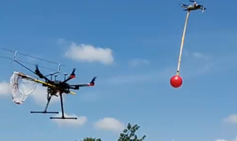
Figure 13. Test setup for stationary and moving ball capture.
Indoor testing: The initial prototype of the proposed end-effector design is first tested in a laboratory environment. The tests carried out are to check (a) the ability of the manipulator to separate the ball, (b) the collection of ball in the mesh, and (c) the working of the grab detector. These tests are performed by engagements between hand-held end-effector and a magnetically attached ball and stick. After observing the functioning of these components and carrying out necessary modifications, the manipulator is integrated to the drone and tested outdoor.
Outdoor testing: A section of the airfield at the Department of Aerospace Engineering, IISc, measuring 100 m $\times$
60 m is used for testing. Grabbing is stationary target is tested using a ball hung from a pole 3 m tall. Moving target capture is tested by suspending the ball from DJI Mavic Pro Platinum with a balsa wood strip with a magnet at its end. The initial tests are carried out at speeds ranging from 2 m/s to 6 m/s and at approximately 10 m above ground. Subsequently, the ball-carrying drone is made to move in figure-of-eight path and manipulator is tested for autonomous capture of the maneuvering target.
$\times$
60 m is used for testing. Grabbing is stationary target is tested using a ball hung from a pole 3 m tall. Moving target capture is tested by suspending the ball from DJI Mavic Pro Platinum with a balsa wood strip with a magnet at its end. The initial tests are carried out at speeds ranging from 2 m/s to 6 m/s and at approximately 10 m above ground. Subsequently, the ball-carrying drone is made to move in figure-of-eight path and manipulator is tested for autonomous capture of the maneuvering target.
The steps followed in testing are the following. The drone with the manipulator is placed at one edge of the arena. The drone with the ball begins moving in a figure-of-eight path. The drone with the manipulator takes off and performs exploration to detect the ball, followed by visual servoing to track the ball along its trajectory. Once the manipulator drone nears the ball, the drone performs a terminal maneuver to capture the ball. The details of software framework employed for autonomous ball grabbing are beyond the scope of the present paper and are available in another publication (see Tony et al. [Reference Tony, Jana, Varun and Bhise33]).
The hardware architecture and the control flow of the integrated system are shown in Fig. 14. The avionics and the on-board computers are listed in Table IV. As shown in Fig. 14, the ball is detected by the camera fixed at the center of the manipulator end-effector. This information is used by the TX2 to compute control commands which is sent to the M600 drone via A3 pro flight controller. The localization is achieved via on-board GPS. When the ball is detached, the limit switches are activated which, via the Arduino nano, sends the information that the ball is captured.

Figure 14. Hardware architecture of the integrated system.
The prototype of the proposed manipulation mechanism was tested using DJI M600. The integrated system with the major components labeled is shown in Fig. 15. A Getac rugged laptop is used as the ground station system. The drone is connected to the ground station and with each other through a WiFi network of 5 GHz created using TP link dc routers.
6.2. Field test results
Flight tests are conducted in the test beds using the designed manipulators and drone set up at the airfield of Indian Institute of Science. The environment is windy which tested the robustness of the designed system. The success rate of the manipulator for static ball is found to be 8/10, and maneuvering ball is found to be 7/10. The 30% failure is contributed mainly by the vision and drone control algorithms. From the manipulator design perspective, the design constraints mentioned in Section 2 are major contributors. If these constraints are relaxed, failures due to design can be mitigated.
Table IV. Avionics and on-board computers of test drone.

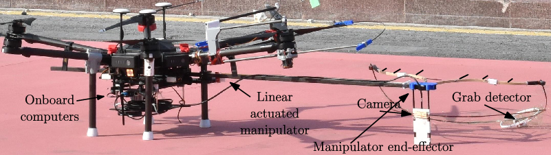
Figure 15. M600 drone integrated with the manipulator.
A snapshot of a grabbing instance for static ball is shown in Fig. 16(a), where the manipulator moves towards the ball and pulls it to detach from the magnetic attachment. Instants of moving ball capture are shown in Fig. 16(b), where the ball is detached from a moving drone and the captured ball is collected in the mesh under the basket. The dropping exercise using the release mechanism at the bottom of the basket end-effector is shown in Fig. 16c. The drone approaches the box in which the ball is to be deposited, followed by actuating the servo to release the ball. The videos of the experimental results from which the above instants are captured can be found in linkFootnote 1 below.
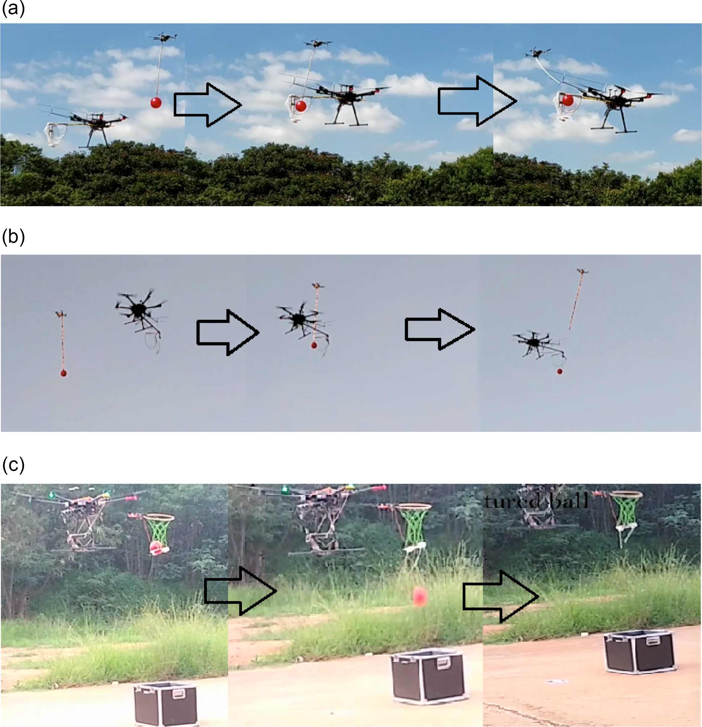
Figure 16. Snapshots of grabbing of (a) static ball (b) moving ball (c) Snap shot of ball dropping.
The energy optimality is validated based on observations during experiments. The drone without any payload has a maximum flight time of 20 min while in motion in non-windy conditions. A drone with an active robotic arm has a maximum flight time of approximately 8–10 min for the same operations. It was observed that the proposed design resulted in a maximum flight time of up to 15 min. Hence, the presented manipulator design is energy optimal in comparison to any active manipulators.
6.3. Discussion
Some interesting observations were made during the experiments. The visual feedback, grabbing algorithm, system dynamics, and the inherent delays in computation were found to have an impact on the success rate. This points to the unavoidable coupling between the manipulator design and the software used to perform the mission. There is a fine relationship between them which decides the success rate.
The proper location of the camera was also found to be an important parameter in successful grabbing, considering the field of view and approach direction. Effects of wind gust are minimal for the proposed design, but any disturbance above 12 m/s brings in some vibrations. Wind speed was externally monitored with an anemometer. Vibrations were not physically measured but the distortions in the images from the manipulator camera indicated the existence of vibrations. Hence, the distortions that did not affect the visual feedback were considered permissible. Sag of the manipulator arm was also observed over time, which was primarily due to the weight of wires at the end-effector side. Nevertheless, proper calibration of sensors resulted in good success rate. With the present design, any object within 0.15 kg and within 0.2 m diameter could be grabbed successfully. The current design can handle a maximum ball weight of 150 g. The DJI M600 drone can handle even larger ball weights while maintaining roll stability, but the manipulator should be redesigned to be structurally stronger to withstand the loads due to the heavier ball. Also, the current manipulator is designed to withstand 4 N detachment force. A higher detachment force could affect the structural integrity of the end-effector. This is because of the choice of materials used in the prototype to address the design requirements of the end-effector (to be lightweight). However, better choice of materials can withstand higher impact forces while grabbing.
Following factors in design contributed towards the success of the manipulator. The hull on top of the end-effector facilitates the capture of the moving ball. The shape of the hull leads the ball in the grab volume to detachment points leading to successful grabbing. The detachment points on the hull ensure separation of the ball from the target drone by applying necessary detachment force. The grab area improves the success rate when there is external disturbance and uncertainty in ball position estimation. The ball anywhere in front of the grab area will be grabbed successfully due to the hull design explained above.
The design requires the integrated system to be within a specific volume. This restricts the grab area of the manipulator end-effector, leading to grab failure in case of large wind disturbance or uncertainty in estimating ball position. This is an aspect of design which contributed to grab failure. However, the majority of grab failures were due to error in vision algorithm and due to slow response of the system in the terminal phase of the mission.
In contrast to active manipulators, for a given amount of power consumed, the success rate of the proposed manipulator is higher. This is because of the additional power needed by the actuators in active manipulators. Also, the proposed design is better in comparison to other designs in terms of time delay associated with its operation. An active manipulator will have a delay in responding while the proposed manipulator does not have any such time delays.
Few design and manufacturing aspects in the final design were compromised to fulfill the requirements, which could be improved in the future variants. The shape of the top portion was an intuitive design and gave good success rates, but a deeper analysis would provide more effective shapes for similar end-effector footprint. The detachment structures and their locations could be analyzed for better performance.
7. Conclusions
This work provided design, development, and testing details of an aerial manipulation mechanism for grasping dynamic targets. The problem statement was inspired by Challenge 1 of MBZIRC 2020. The major complexities involved in the design and development were discussed in detail. The conceptual design for the task was presented, describing the reasons for design and the material choice. The experimental results and relevant observations are also reported in this paper. The flight test results for grabbing moving ball and dropping at a predefined location are demonstrated. The obvious and unavoidable coupling between the hardware design and software modules are pointed out. However, precise design and modeling of the software modules are found to guarantee good performance of the system. The repeatability and success rates of the final configurations are reported, and possible developments on the final design are also presented. The manipulator has been designed for a ball grabbing in this work but can be modified for many other applications including counter-UAV defense, fruit picking in orchards, package passing between drones in long-distance delivery, repair, and monitoring of inaccessible structures, etc.
Acknowledgements
We acknowledge members of GCDSL for their valuable suggestions in development of the manipulator. The contributions of Integrative Multiscale Engineering Materials and Systems (iMEMS) lab and Advanced Materials and Processing Laboratory (AMPL), especially Sagar K. and Abhishek Nagaraja, towards prototyping manipulator components, deserves thankful mention. We acknowledge our collaborator, Tata Consultancy Services, for their contributions towards this work.
Author Contributions
BVV designed the manipulator. BVV and LAT prototyped the manipulator and wrote the paper. MSG was the pilot for the tests and dealt with the hardware integration. SJ, VVP and AAB carried out the software integration to automate the process and helped with the tests. SS conceived the design idea and wrote the paper. DG led the project, reviewed work progress, and wrote the paper.
Financial Support
This work is partially supported by Robert Bosch Center for Cyber Physical Systems, (IISc) and Khalifa University, Abu Dhabi, UAE.
Competing Interest Declaration
Competing interests: The authors declare none.


 Open access